Note: Descriptions are shown in the official language in which they were submitted.
CA 02732355 2011-01-27
WO 2010/014834 PCT/US2009/052287
METHODS AND DEVICES FOR CRIMPING SELF-EXPANDING DEVICES
CROSS REFERENCE TO RELATED APPLICATIONS
[0001] This application claims priority to U.S. Provisional Application Serial
No. 61/085,795 filed August 1, 2008, the entirety of which is hereby
incorporated by
reference in its entirety.
FIELD
[0002] The present invention relates generally to methods and devices for
crimping self-expanding devices.
BACKGROUND OF THE INVENTION
[0003] There is a movement toward using minimally invasive approaches for
treating conditions or diseases. Because they can be delivered in an
unexpanded
configuration, self-expanding devices may be useful to provide a minimally
invasive way to
maintain, open, or dilate bodily structures such as veins, arteries, ureters,
urethras, hollow-
body organs, nasal passages, sinus cavities, and the like. These self-
expanding devices may
serve a number of therapeutic functions, and may be used to release one or
more drugs to a
target location. Furthermore, self-expanding devices may be designed to
degrade over time.
For example, self-expanding devices may be used to provide anatomical support
to one or
more sinus openings or ostia following functional endoscopic sinus surgery.
[0004] In order to provide a self-expanding device to an anatomical location,
generally it first must be reduced to an unexpanded configuration. There may
be problems,
however, with crimping a self-expanding device to an unexpanded configuration.
These
problems may arise from the geometry of the self-expanding device, from
maintaining the
sterility of the device, or from a number of other sources. Thus it may be
useful to provide
devices to crimp a self-expanding device to an unexpanded configuration.
BRIEF SUMMARY OF THE INVENTION
[0005] Described here are devices and methods for crimping self-expanding
devices. The crimping devices described here may be useful for crimping a
variety of
different self-expanding devices. In some variations, the self-expanding
device is
1
CA 02732355 2011-01-27
WO 2010/014834 PCT/US2009/052287
biodegradable. In other variations, the self-expanding device is bio-durable.
The self-
expanding device may comprise, incorporate, or deliver one or more drugs or
active agents,
and the crimping device may be configured to be compatible with such drug or
active agent
so as not to destroy or limit its efficacy. In some variations, the devices
described here have
one or more crimping members. Generally, a crimping member is a structure that
may
engage a self-expanding device to reduce the self-expanding device to an
unexpanded
configuration from an expanded configuration. In some variations, the crimping
members
comprise a suture, wire, ribbon, guiding hoop, pusher, prong, holding bar,
balloon, jaws, a
combination thereof, or the like. Any crimping member, or combination of
crimping
members, may be used, as appropriate, with any of the crimping devices
described here.
Additionally, any crimping member may include one or more handles.
[0006] In some variations, crimping devices are described here having a
crimping member, where the crimping member engages the self-expanding device
to reduce
the self-expanding device to an unexpanded configuration from an expanded
configuration,
and where the crimping device engages an applicator or storage member to hold
the self-
expanding device in its unexpanded configuration. The crimping devices
described here may
additionally include one or more holding structures configured to hold one or
more self-
expanding devices in their expanded configurations, or in some instances,
their un-expanded
configurations. The holding structure may define an aperture, but need not.
The holding
structure may be or comprise a hoop, canister, cage, plate, funnel, rod,
sheath, wire, ribbon,
ring, a combination thereof, or the like. The holding structure may be made of
a single
continuous component, or may be made of two or more separate components.
Additionally,
each component of the holding structure may be made of one material, or may be
made from
a combination of materials.
[0007] In some variations, the holding structure may include one or more
passage units. Generally, passage units provide a structure through which a
crimping
member may pass into or out of a holding structure. Examples of suitable
passage units
include, but are not limited to, slits, slots, holes, grooves, contours,
pulleys, and rollers.
Additionally, the holding structure may include one or more tracks. When a
holding structure
includes one or more tracks, it may additionally include one or more pins that
are slidably
disposed in one or more of the one or more tracks.
2
CA 02732355 2011-01-27
WO 2010/014834 PCT/US2009/052287
[0008] In other variations of the devices described here, the crimping devices
may have a holding structure, where the holding structure is configured to
hold therein the
self-expanding device in an expanded configuration, and a crimping control,
where
movement of the crimping control relative to the holding structure causes the
crimping device
to reduce the self-expanding device to an unexpanded configuration. In some
variations, the
crimping control rotates relative to the holding structure. The holding
structure may be any
holding structure, or combination of holding structures, and may include any
feature or
combination of features as described above. Additionally, the crimping control
may include
tracks. In variations in which both the holding structure and the crimping
control include
tracks, the crimping device may include pins that may be slidably disposed
within the tracks
of both the crimping control and the holding structure. In some of these
variations, the tracks
of the holding structure project radially from a center of the holding
structure, and the tracks
of the crimping control curve radially away from a center of the crimping
control. In some
variations, the crimping device includes one or more crimping members. The one
or more
crimping member may be any suitable crimping member or combination of crimping
members as described above. In some of these variations, the crimping control
engages one
or more of the one or more crimping members.
[0009] In still other variations of the crimping devices described here, the
crimping devices have a crimping portion where the crimping portion has a
first end, a
second end, an interior surface and a plurality of slits running between the
first and second
ends, where the cross-sectional area of the crimping portion decreases from
the second end to
the first end, and where the interior surface of the crimping portion is
configured to house the
self-expanding device in an expanded configuration. These variations may also
include a
pusher, where the pusher includes a plurality of prongs that engage one or
more of the
plurality of slits and where movement of the pusher from the second end of the
crimping
portion toward the first end of the frame compresses the self-expanding device
into an
unexpanded configuration. Additionally, the crimping portion may define an
aperture
through which the self-expanding device may be retrieved. In some variations,
the crimping
device may include a storage zone that is configured to releasably hold the
self-expanding
device in an unexpanded configuration. In other variations, the crimping
device may be
configured for attachment to an applicator for delivery of the self-expanding
device to a
target location. The crimping device may or may not be integral with, or
permanently
connected or coupled to a delivery applicator.
3
CA 02732355 2011-01-27
WO 2010/014834 PCT/US2009/052287
[0010] Other variations of the crimping devices described here have a first
plate
and a second plate, where the first plate and second plate are slidably
engagable to define an
aperture and where the aperture has a cross-sectional area that changes when
the first plate is
slid relative to the second plate. In some variations, the crimping device may
include a third
plate. This third plate may be fixedly attached to one or more of the other
plates, or may be
slidably engagable with one ore more the other plates. Additionally, the
aperture defined by
the plates may have a substantially symmetrical shape, but need not. In some
variations, the
aperture has a substantially diamond shape.
[0011] Still other variations of crimping devices are described here having a
crimping portion that may be configured to reduce the self-expanding device
from an
expanded configuration to an unexpanded configuration, a storage zone that may
be
configured to house the self-expanding device in its unexpanded configuration,
and an
applicator engagement portion that may be configured to engage a distal end of
an applicator.
In some variations, the crimping device may have one or more blades or cutting
structures.
In other variations, the crimping device may include a funnel.
[0012] Also described here are methods for crimping a self-expanding device.
Generally, any of the devices described here may be used to crimp a self-
expanding device.
Furthermore, any of the methods described here may be used to crimp any
suitable self-
expanding device, such as a biodegradable self-expanding device. In some
methods, a self-
expanding device may be crimped directly into the interior of a delivery
device or storage
member using a crimping device. In some of these methods, the crimping device
is integral
with the delivery device or storage member. In some of these methods, the
crimping device
may have a funnel. In other methods, the crimping device may have one or more
crimping
members. In still other methods the crimping device may define an aperture.
[0013] In other variations of the methods described here, a self-expanding
device may be crimped using a crimping device and may be retrieved from the
crimping
device via a delivery device. In other variations, the crimped self-expanding
device may be
retrieved through an aperture defined by the crimping device. In some methods,
the crimping
device may include one or more connection members. Examples of suitable
connection
members include, but are not limited to sutures, ribbons, guiding hoops,
pushers, balloons,
combinations thereof, and the like. In other methods, the crimping device has
one or more
4
CA 02732355 2011-01-27
WO 2010/014834 PCT/US2009/052287
handles. In still other methods the crimping device may include a holding
structure such as a
hoop, or may include one or more passage units.
[0014] Still other methods for crimping a self-expanding device are described
here comprising crimping a self-expanding device to an unexpanded
configuration using a
crimping device and maintaining the self-expanding device in its unexpanded
configuration
using a water-soluble component.
[0015] Also described here are methods of using a self-expanding device.
Generally these methods comprise storing the self-expanding device in its
expanded
configuration, crimping the self-expanding device to its unexpanded
configuration
immediately prior to use, and delivering the self-expanding device at an
anatomical location.
These methods may be utilized for biodegradable self-expanding devices. In
some of these
methods, the expanded self-expanding device is stored in a protective
container.
BRIEF DESCRIPTION OF THE DRAWINGS
[0016] FIGS. 1-5 are illustrative depictions of suitable variations of
crimping
devices having one or more crimping members and one or more handles.
[0017] FIGS. 6A-6D depict an illustrative method of crimping a self-expanding
device using a suitable variation of the crimping devices described here.
[0018] FIGS. 7A-7D are illustrative depictions of a suitable crimping device
having a holding structure and a crimping member. FIGS. 7A and 7B are
perspective views
showing the crimping device engaging a self-expanding device in an expanded
configuration
and an unexpanded configuration, respectively. FIGS. 7C and 7D are top views
showing the
crimping device engaging a self-expanding device in an expanded configuration
and an
unexpanded configuration, respectively.
[0019] FIGS. 8-9 are illustrative depictions of suitable variations of holding
structures.
[0020] FIGS. IOA-IOC depict an illustrative variation of a crimping device
having a holding structure and a crimping member. FIG. I OA is a perspective
view of the
entire crimping device. FIGS. 10B and 1OC are cutaway views of the interior of
the crimping
device of FIG. 10A.
CA 02732355 2011-01-27
WO 2010/014834 PCT/US2009/052287
[0021] FIG. 11 is an illustrative depiction of a suitable variation of a
crimping
device having one or more crimping controls.
[0022] FIGS. 12A-12D show another variation of a crimping device having one
or more crimping controls. FIG. 12A is a perspective view of the crimping
control. FIG.
12B is a perspective view of the entire crimping device and FIGS. 12C and 12D
are bottom
views of the crimping device of FIG. 12B.
[0023] FIGS. 13-17 depict illustrative variations of additional features that
may
be included in any of the crimping devices described here.
[0024] FIGS. 18A-22B depict illustrative variations of suitable crimping
devices described here, having crimping portions.
[0025] FIGS. 23A-24B depict illustrative variations of suitable crimping
devices described here having two or more plates.
[0026] FIGS. 25-28D are illustrative depictions of suitable variations of
crimping devices having one or more crimping members and one or more handles.
[0027] FIGS. 29A-29E depict an illustrative variation of a crimping device
having one or more crimping members.
[0028] FIGS. 30A-33 depict illustrative variations of additional features that
may be included in any of the crimping device described here.
[0029] FIGS. 34A-34C show another variation of a crimping device having one
or more crimping controls.
[0030] FIGS. 35A and 35B are illustrative depictions of suitable crimping
devices having crimping portions.
[0031] FIGS. 36A-38F show illustrative depictions of suitable variations of
crimping devices having crimping tubes.
[0032] FIGS. 39 and 40 depict illustrative variations of crimping devices that
may crimp multiple self-expanding devices.
6
CA 02732355 2011-01-27
WO 2010/014834 PCT/US2009/052287
DETAILED DESCRIPTION OF THE INVENTION
[0033] Described here are devices for crimping a self-expanding device into an
unexpanded configuration. Methods for crimping self-expanding devices are also
described
here. This self-expanding device may be biodegradable, but need not be. For
example, the
self-expanding devices may be bio-durable, or made of one or more bio-durable
components
(e.g., metals, biod-durable polymers, etc.). Furthermore, the devices and
methods described
here may be utilized to reduce self-expanding devices of a variety of shapes
and
configurations. For example, the self-expanding device may have a tubular
structure, such as
a coil. The self-expanding device may have a crown shape, or a substantially
repeating
diamond pattern. The crimping devices and methods described here may find
particular
utility with the self-expanding devices described in application No.
61/058,803, which is
hereby incorporated by reference herein in its entirety. Additionally, the
crimping devices
described here may be configured to crimp multiple self-expanding devices.
[0034] Methods for crimping a self-expanding device generally involve using
one of the devices described here to engage and reduce a self-expanding device
from an
expanded configuration to an unexpanded configuration. In some variations, the
crimped
self-expanding device is then transferred into a storage member, applicator or
other device.
In some methods, the self-expanding device may be crimped directly into a
storage member,
applicator, or other device. In other methods, the self-expanding device may
be removed
from the crimping device using a storage member, applicator, or other device
(e.g., through
one or more apertures or the like). In still other methods, an additional
device may be used to
move the crimped self-expanding device from the crimping device to a storage
member,
applicator, or other device. In some methods, part or all of the crimping
device is disengaged
from the self-expanding device following crimping.
[0035] In some instances, it may be desirable to maintain a self-expanding
device in an expanded configuration until a time immediately prior to delivery
(e.g., minutes,
hours, or days). As such, in some methods, a self-expanding device may be
stored in an
expanded configuration. In some of these methods, the self-expanding device
may be stored
in and/or on a protective container. When a self-expanding device is going to
be delivered to
an anatomical location, the self-expanding device may be crimped at the site
of the delivery
procedure, and may be crimped prior to its delivery at the anatomical
location. Because the
crimping devices described here may be used to crimp a self-expanding device
during a
7
CA 02732355 2011-01-27
WO 2010/014834 PCT/US2009/052287
sterile procedure, it may be desirable for the crimping devices described here
to be
sterilizable.
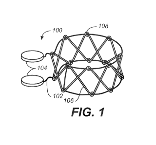
[0036] Some of the crimping devices described here comprise one or more
crimping members. In some of these variations, the crimping devices may
additionally
contain one or more handles, but need not. FIG. 1 shows one suitable variation
of crimping
device (100), comprising crimping member (102) and handles (104), engaging
self-expanding
device (106) comprising loops (108). While shown in FIG. 1 as being a suture,
crimping
member (102) may have any suitable configuration. Generally, crimping members
are
configured to engage a self-expanding device to reduce the self-expanding
device to an
unexpanded configuration. Examples of suitable crimping members include, but
are not
limited to, sutures, wires, ribbons, guiding hoops, pushers, prongs, holding
bars, jaws,
balloons, combinations thereof, and the like.
[0037] A crimping member may additionally include one or more structures to
aid in engagement between the crimping member and the self-expanding device.
For
example, FIG. 25 shows one variation of device (2500) comprising handles
(2509) and
crimping member (2502) with ring (2504) and hooks (2506), and engaging self-
expanding
device (2508). Crimping member (2502) may have any combination of hooks (2506)
and
rings (2504). For example, crimping member may comprise zero, one, or two or
more hooks
(2506) and zero, one, or two or more rings (2504). Generally, hooks (2506) and
rings (2504)
may be placed around or through any suitable portion of self-expanding device
(2508). In
variations, in which self-expanding device (2508) comprises loops (2510),
hooks (2506) or
rings (2504) may engage one or more of these loops (2510). Although shown in
FIG. 25 as
being slidably disposed along crimping members (2502), rings (2504) and hooks
(2506) need
not be. Indeed, rings (2504) and hooks (2506) may be fixidly attached to
crimping members
(2502). In some variations, some of the rings (2504) and hooks (2506) may be
slidably
disposed along crimping members (2502) while others may be fixidly attached to
crimping
members (2502).
[0038] In other variations, the crimping member may include a sheath (e.g. a
flexible sheath, a collapsible sheath, a sleeve, a netting or a mesh). FIG. 2
shows one such
variation of crimping device (200), comprising crimping member (202), first
handle (204),
second handle (206), and sheath (208). This sheath (208) may aid in engagement
with a self-
expanding device (not shown) by increasing the surface area contact between
crimping
8
CA 02732355 2011-01-27
WO 2010/014834 PCT/US2009/052287
member (202) and the self-expanding device. In some variations, a crimping
member may
comprise a netting or mesh that may enclose a self-expanding device. For
example, FIGS.
26A and 26B show one variation of crimping device (2600) comprising crimping
member
(2602) having netting (2604) and handles (2606). A self-expanding device (not
shown), may
be placed within netting (2604). As handles (2606) are pulled away from each
other, netting
(2604) is stretched in a horizontal direction, as indicated by first arrows
(2608), which causes
the width of the netting (2604) to be reduced, as indicated by second arrows
(2610). This
may, in turn, crimp a self-expanding device.
[0039] The crimping devices described here may have any number of
crimping members. In some variations, the crimping device may have two or more
crimping
members. FIG. 3 shows one such variation of crimping device (300), comprising
first
crimping member (302), second crimping member (304), sheath (306), first
handle (308),
second handle (310) including pusher (312), and storage member (314).
[0040] In variations where the crimping device comprises handles, the
crimping device may have any number of handles. Indeed, the crimping device
may have
three or more handles, two handles, one handle, or no handles. Furthermore,
handles may
have any shape or configuration, but need not have the same shape or
configuration. In some
variations, the handle is configured to attach to one end of one crimping
member. In other
variations, such as those shown in FIG. 3, the handle is configured to attach
to two or more
ends of crimping members. In some of these variations, the handle may attach
to two or
more ends of the same crimping member. In other variations, the handle may
attach to one or
more ends of two or more different crimping members. In still other
variations, the handle is
configured such that one or more ends of one or more crimping members may pass
through
the handle, such as the second handle (206) in FIG. 2. In some of these
variations, the handle
may be configured to both attach to one or more ends of one or more crimping
members and
allow one or more ends of one or more crimping members to pass therethrough.
This may
allow a user to pull a crimping member through a handle while keeping the
other end of the
crimping member stationary relative to the handle.
[0041] Additionally, a handle may have one or more additional features that
may be useful in the operation of the crimping device. In some variations the
handle may
comprise a pusher, such as the second handle (310) in FIG. 3. This pusher may
serve a
number of functions. In variations in which the crimping device includes a
storage member,
9
CA 02732355 2011-01-27
WO 2010/014834 PCT/US2009/052287
as described in more detail below, the pusher may be used to eject a crimped
self-expanding
device from the storage member. Additionally, the pusher may be used to hold a
storage
member when the storage member is not engaging a self-expanding device.
[0042] In other variations, the handle may include a structure that allows the
crimping device to engage or attach to a storage member, applicator, or other
device. FIG. 4
shows one such variation of crimping device (400), comprising crimping member
(402), first
handle (404) and second handle (406) having applicator guide (408). In the
variations shown
in FIG. 4, applicator guide (408) may be placed over the distal end of a
storage member,
applicator or other device (not shown). In other variations, applicator guide
(408) may fit
within, clip onto, or otherwise engage a storage member, applicator, or other
device.
Furthermore, while shown in FIG. 4 as being a cylindrical structure,
applicator guide (408)
may have any configuration that is capable of positioning a storage member,
applicator or
other device relative to a self-expanding device (not shown). In some
variations, applicator
guide may be a partial-cylinder, cone, funnel, clip, clamp, or combination
thereof.
Furthermore, applicator guide may have a non-circular cross-section, which may
be
determined by or based upon the size and shape of the applicator, storage
member, or other
device.
[0043] In some variations, the crimping device may include a storage member,
which may, for example, hold a self-expanding device in an unexpanded
configuration. FIG.
3 illustrates one variation of storage member (314). While shown in FIG. 3 as
being a
cylinder with a flaring end, storage member (314) may have any suitable
configuration. The
shape, dimensions and configuration of storage member (314) may be dependent
on the shape
of the crimped self-expanding device, or may be designed to hold the self-
expanding device
in a certain way. For example, storage member (314) may be a cylinder, a
partial cylinder, a
cone, a frustoconical shape, a box, a sphere, or a combination thereof.
Furthermore, the
storage member (314) may have any cross-sectional shape, including, but not
limited to,
ovals, circles, rectangles, diamonds, other polygons or shapes with irregular
geometries. In
some variations, the storage member may be advanced over one or more crimping
members
to hold a self-expanding device in an unexpanded configuration. In other
variations, the
storage member may be capable of attaching directly to a self-expanding
device. For
example, the storage member may include a clasp or clip that is capable of
attaching around a
crimped self-expanding device.
CA 02732355 2011-01-27
WO 2010/014834 PCT/US2009/052287
[0044] In some variations, the storage member may be configured to be used as
an applicator to deliver a crimped self-expanding device to an anatomical
location. In other
variations, the storage member may be configured to attach to one or more
storage members,
applicators, or other devices. One or more portions of any suitable crimping
device described
here may be configured to be used as an applicator to deliver a crimped self-
expanding
device to an anatomical location, or may be configured to attach to one or
more storage
members, applicators, or other devices to deliver a crimped self-expanding
device to an
anatomical location.
[0045] As described hereinthroughout, the crimping devices described here
may engage a self-expanding device in a number of different ways. This
engagement may
depend on the shape, structure, or configuration of the self-expanding device,
but may depend
on other factors as well. In some variations, such as those shown in FIGS. 2-
4, one or more
crimping members wrap around the outside of the self-expanding device. In
variations in
which the crimping member contains hooks or rings, these hooks or rings may be
attached to
portions of the self-expanding device. In other variations, one or more
crimping members are
wound around portions of the self-expanding device. For example, FIG. 5 shows
one such
variation of crimping device (500) comprising crimping member (502) and
handles (504),
and engaging self-expanding device (506) having a substantially repeating
diamond pattern
comprising junctions (508). As shown in FIG. 5, crimping device may be wound
around the
junctions (508) of self-expanding device (506). While shown in FIG. 5 as being
wound
around every junction (508), crimping member (502) need not be. Indeed,
crimping member
(502) may be wound around all, some, or none of the junctions (508).
Additionally, the
crimping member may be wound around one or more different portions of the self-
expanding
device.
[0046] In variations in which the self-expanding device has one or more loops,
the crimping device may be threaded through one or more of these loops. For
example,
crimping member (102) of crimping device (100) shown in FIG. 1 is threaded
through loops
(108) of self-expanding device (106). While shown in FIG. 1 as being threaded
through each
loop (108), crimping member (102) need not be. Indeed, the crimping member
(102) may be
threaded through all, some, or none of the loops (108).
[0047] It should be appreciated that a crimping device may engage a self-
expanding device in any of the ways or combinations of the ways described
above, as well as
11
CA 02732355 2011-01-27
WO 2010/014834 PCT/US2009/052287
include any feature or combination of features described herein. Furthermore,
in crimping
devices that contain two or more crimping members, each crimping member may
engage a
self-expanding device in the same manner or in different manners.
[0048] Any of the devices described above may be used to crimp a self-
expanding device from an expanded configuration to an unexpanded
configuration. FIGS.
6A-6D illustrate one method of crimping a self-expanding device (600) having
loops (602)
using crimping device (604) having crimping members (606), first handle (608),
second
handle (610) comprising pusher (612), and storage member (614). Initially, the
crimping
device (604) may engage self-expanding device (600), as shown in a perspective
view in FIG.
6A and in a side view in FIG. 6B. While shown in FIGS. 6A-6D as having
crimping member
(606) threaded through loops (602), the crimping device (604) may engage self-
expanding
device (600) in any suitable manner as described above. Generally, the first
(608) and second
(610) handles may be pulled away from each other to reduce self-expanding
device (600) to
an unexpanded configuration, as shown in FIG. 6C.
[0049] Once self-expanding device (600) has been crimped, storage member
(614) may be advanced along crimping member (606) to at least partially hold
self-expanding
device (600) in its reduced configuration, as shown in FIG. 6D. Crimping
member (600)
and/or a combination of first (608) and/or second (610) handles may then be
disengaged from
the self-expanding device (600), but they need not be. Additionally, pusher
(612) may be
used to eject self-expanding device (600) from storage member (614) into an
applicator or
other device, or to eject self-expanding device (600) at a target location.
[0050] In other methods, the crimped self-expanding device may be
transferred directly into an applicator or other device. In variations in
which the crimping
device includes an applicator guide, the applicator guide may be used to
position the storage
member, applicator, or device relative to the self-expanding device. It should
be appreciated
that any of the devices as described above may include any suitable
combination of features
described herein and may be used to reduce a self-expanding device to an
unexpanded
configuration.
[0051] FIGS. 27A-27C show another variation of crimping device (2700)
comprising cylinder (2702) defining aperture (2704), suture (2706) with handle
(2708), and
crimping members (2710) comprising holding bars (2712), loops (2714) and
eyelets (2716).
12
CA 02732355 2011-01-27
WO 2010/014834 PCT/US2009/052287
In some variations, crimping members (2710) may be rotatably attached to
cylinder (2702),
but need not be. Additionally, crimping members (2710) may bend at loops
(2714) to define
space (2718) in which a self-expanding device (not shown) may be placed, as
shown in FIG.
27A. In some variations, suture (2706) may be threaded through one or more
eyelets (2716).
In these variations, handle (2708) may be pulled away from cylinder (2702) to
close crimping
members (2710) around the self-expanding device, as shown in FIG. 27B. This
may hold the
self-expanding device within crimping device (2700), and may additionally
begin crimping
the self-expanding member. Pulling handle (2708) further away from cylinder
(2702) may
cause the holding bars (2712) to straighten at loops (2714). This may in turn
further crimp
the self-expanding device. In some variations, this crimping may cause the
self-expanding
device to exit cylinder (2702) via aperture (2704). In other variations, the
crimped self-
expanding device may be removed via aperture (2704).
[0052] While shown in FIGS. 27A-27C as having loops (2714), holding bars
(2712) need not. Indeed, holding bars (2712) may have hinges or joints, or may
be made
from a flexible material that is capable of straightening when a certain force
is applied to it.
Furthermore, in variations in which the holding bars (2712) have loops,
hinges, or joints, they
may have any number or combination of loops, hinges, and joints. Furthermore,
while shown
as being attached to cylinder (2702), holding bars (2712) may be attached to
any suitable
structure having any suitable size and shape.
[0053] FIGS. 28A-28D show another variation of crimping device (2800),
comprising base (2802), rim (2804), handle (2806) and a plurality of crimping
members
(2808). Crimping members (2808) may be attached to base (2802), and base
(2802) may in
turn be attached to rim (2804) and handle (2806). Generally, base (2802) may
be able to
move between an open position, as shown in a perspective view in FIG. 28A, and
a closed
position, as shown in a perspective view in FIG. 28B. In some variations,
handle (2806) may
be used to move base (2802) between open and closed positions. In other
variations, when
the base (2802) is in an open position, crimping members (2808) are directed
outward,
defining space (2810). When the base (2802) is moved into the closed position,
crimping
members (2808) may rotate inward, decreasing the size of space (2810). To
crimp a self-
expanding device using crimping device (2800), self-expanding device may be
placed in
space (2810) when the base (2802) is in an open position, as shown in a side
view in FIG.
28C. When handle (2806) moves base (2802) into a closed position, crimping
members
13
CA 02732355 2011-01-27
WO 2010/014834 PCT/US2009/052287
(2808) may engage self-expanding device to crimp self-expanding device to an
unexpanded
configuration, as shown in a side view in FIG. 28D.
[0054] In some variations, crimping devices may comprise one or more
crimping members that have one or more jaws. FIGS. 29A-29E show variations of
crimping
members comprising one or more jaws. More specifically, FIG. 29A shows one
variation of
crimping device (2900) comprising crimping member (2902) in an open position
and having
base portion (2904) and alternating jaws (2906). In these variations, crimping
member
(2902) may define a space (2908), and may be configured to change to a closed
position in
which alternating jaws (2906) move past each other to reduce the size of space
(2908), as
shown in FIG. 29B. In some variations, crimping member (2902) may be made of a
material
that has a natural tendency to move the crimping member (2904) to a closed
position. In
other variations, the crimping member (2902) may close in response to an
external force.
While shown in FIGS. 29A and 29B as being a single component, crimping member
(2902)
may be made of two or more components. For example, FIG. 29C shows one such
variation
of crimping member (2910) comprising hinged portions (2912), each having
alternating jaws
(2914) and handles (2916).
[0055] To crimp a self-expanding device (not shown) using crimping device
(2900), the self-expanding device may be placed within space (2908) when
crimping member
(2902) is an open position. When the crimping member (2902) moves to a closed
position,
alternating jaws (2906) and base portion (2904) may engage the self-expanding
device to
crimp the self-expanding device to an unexpanded configuration. In some
variations, the
self-expanding device may be crimped from a storage structure. FIG. 29D shows
one
variation of storage structure (2918) comprising holder (2920), base (2922)
and separator
(2924). Generally, a self-expanding device (not shown) may be placed around
holder (2920)
and stored in an expanded configuration. A crimping device may then be placed
around
storage structure (2918). FIG. 29E shows the crimping member (2910) of FIG.
29C placed
around the storage structure (2918) of FIG. 29D. Although shown in FIGS. 29D
and 29E as
having separator (2924), storage structure (2918) need not. In variations that
do include a
separator (2924), the separator (2924) may serve to hold the alternating jaws
(2914) apart.
The storage device (2918) may be pulled through crimping member (2910) to
leave the self-
expanding device within crimping member (2910). In some variations, crimping
member
(2910) may comprise a lip (not shown) or some other structure configured to
ensure that the
14
CA 02732355 2011-01-27
WO 2010/014834 PCT/US2009/052287
self-expanding device remains within crimping member (2910). As this point,
the crimping
member (2910) may change from an open position to a closed position in order
to crimp the
self-expanding device as described above.
[0056] In some variations, the crimping devices include a holding structure
and
one or more crimping members. In these variations, the holding structure is
generally
configured to hold a self-expanding device in an expanded configuration,
although it is noted
that in other configurations the holding structure may be generally configured
to hold the
self-expanding device in an un-expanded configuration. One or more crimping
members
may then engage the self-expanding device to reduce the self-expanding device
to an
unexpanded configuration. The self-expanding device may either be crimped
directly into a
storage member, applicator, or other device, or may be transferred following
crimping to a
storage member, applicator, or other device.
[0057] FIGS. 7A-7D illustrate one such variation of crimping device (700),
comprising crimping member (702) and holding structure (704). As shown in
FIGS. 7A-7D,
holding structure (700) includes passage units (706), shaping portion (708),
and grips (710).
Also shown there is self-expanding device (712). FIG. 7A shows a perspective
view and
FIG. 7C shows a top view of crimping device (700) holding self-expanding
device (712) in
an expanded configuration. Crimping member (702) may then engage self-
expanding device
(712) to reduce self-expanding device (712) to an unexpanded configuration, as
shown in a
perspective view in FIG. 7B and in a top view in FIG. 7D.
[0058] While shown in FIGS. 7A-7D as being a hoop, holding structure (704)
may be any suitable structure. Examples of suitable holding structures
include, but are not
limited to, hoops, canisters, cages, rods, and plates defining one or more
apertures. The
holding structures may be made of one or more separate pieces. Furthermore,
the holding
structures may have any suitable dimensions, shapes, or configurations. For
example, while
the hoop shown in FIGS. 7A-7D has a generally circular shape, the holding
structure may
define any suitable shape. Indeed, the holding structure may have an irregular
shape or one
that approximates an oval, a triangle, a rectangle, a polygon or the like.
This shape may be
determined by or may be based on the shape of the self-expanding device in its
expanded
configuration, but need not be. In some variations, the size and/or shape of
the holding
structure may be adjusted or adjustable to accept self-expanding devices of
different sizes.
Furthermore, although the hoop in FIGS. 7A-7D is shown as having a height less
than that of
CA 02732355 2011-01-27
WO 2010/014834 PCT/US2009/052287
the self-expanding device, the holding structure may have any suitable height.
In some
variations, the holding structure has a larger height than the height of the
self-expanding
device. In still other variations, the height of the holding structure may
vary throughout the
crimping device. In addition, the holding structure may include one or more
additional
features to help maintain the self-expanding device in a desired configuration
(whether
expanded or un-expanded), e.g., rings (stationary or slidable), wires,
ribbons, hoops, sheaths
(stationary or slidable), pushers, and the like.
[0059] Furthermore, these crimping devices may include any suitable crimping
member or combination of crimping members as described above. The crimping
members
may also contain any feature or combination of features as described above.
While shown in
FIGS. 7A-7D as having one crimping member, the crimping device may incorporate
any
number of crimping members. Indeed, the crimping device may contain two or
more
crimping members. For example, in some variations the crimping device may
contain two
sutures encased within a sheath, similar to the crimping members shown in FIG.
3. In other
variations, the crimping device may contain a plurality of crimping members,
wherein each
crimping member has a hook that may be used to engage the self-expanding
device.
[0060] The crimping device may have any number of handles. These handles
may have any shape or configuration as described above, and may be attached to
any, all, or
none of the crimping members. Furthermore, the holding structure may have one
or more
handles or grips. These handles or grips may have any suitable shape or
configuration.
[0061] As described hereinthroughout, the crimping device may engage a self-
expanding device in a number of different ways. This engagement may depend on
the shape,
structure, or configuration of the self-expanding device. In some variations,
the crimping
member may wrap around the self-expanding device and sit between the self-
expanding
device and the holding structure, as illustrated by crimping device (700)
shown in FIGS. 7A-
7D. In other variations, one or more crimping members may be wound around one
or more
portions of the self-expanding device. In variations in which one or more of
the crimping
members include hooks or rings, the hooks or rings may be attached or affixed
to the self-
expanding device. In variations in which the self-expanding device has one or
more loops,
one or more crimping devices may be threaded through all, some, or none of the
loops. In
variations in which one or more of the crimping members are balloons or
pushers, the
crimping member may push against the outer surface of the self-expanding
device.
16
CA 02732355 2011-01-27
WO 2010/014834 PCT/US2009/052287
[0062] Furthermore, the crimping members may engage a holding structure in a
number of ways. In some variations, one or more ends of one or more crimping
members are
attached to the holding structure. In other variations, one or more ends of
one or more
crimping members pass through the holding structure via one or more passage
units. By
moving a portion of a crimping member through a passage unit, a user may
control the
amount of engagement between the crimping member and a self-expanding device.
This
may, in turn, control the amount of crimping of the self-expanding device. For
example, in
crimping device (700) shown in FIGS. 7C and 7D, pulling the ends of crimping
member
(702) through passage units (706) reduces the amount of crimping member (702)
that resides
within holding structure (700), which in turn causes crimping member (702) to
pull against
self-expanding device (712).
[0063] The passage units may be any suitable structure that is capable of
allowing at least a portion of a crimping member to pass through at least a
portion of a
holding structure. Examples of suitable passage units include, but are not
limited to slits,
slots, holes, grooves, contours, pulleys, and rollers. Passage units may have
any suitable
shape and dimension. In some variations, the size and shape of the passage
units may be
determined by the dimensions of the crimping member. Additionally, passage
units may be
sized and shaped to accept one or more portions of one or more crimping
members. As such,
when a crimping device contains passage units, each crimping member of that
crimping
device may pass through all, some, or none of the passage units. For example,
in some
variations, such as the one shown in FIGS. 7A & 7B, each end of a crimping
member passes
through a different passage unit. In other variations, both ends of a crimping
member pass
through the same passage unit. In still other variations, one end of a
crimping member is
attached to the interior of the holding structure, and the other end passes
through a passage
unit.
[0064] In some instances, it may be desirable to limit the amount that a self-
expanding device is crimped. Thus, the crimping device may include one or more
features
that are designed to limit a device's crimping. In some variations, one or
more of the
crimping members may contain a visual indicator. In these variations, one or
more crimping
members may have color-coded regions or other markers. In variations in which
crimping
occurs by pulling a crimping member through a holding structure, that crimping
device may
be configured such that when sufficient crimping has occurred, the visual
indicator becomes
17
CA 02732355 2011-01-27
WO 2010/014834 PCT/US2009/052287
visible outside of the holding structure, signaling the user to stop crimping.
In variations in
which crimping occurs by pushing a crimping member into a holding structure,
the crimping
device may be configured such that when sufficient crimping has occurred, the
visual
indicator ceases to be visible outside of the holding structure.
[0065] In other variations, the crimping member may contain one or more stops
or other features that are unable to pass through a passage unit, and thus
limit the ability of
the crimping member to pass either into or out of the holding structure. The
crimping
member may be configured such that when the device has been sufficiently
crimped, the
stops engage the passage unit and prevent any further crimping. Examples of
suitable stops
include studs, rings, and knots that are attached to a crimping member.
[0066] In other instances it may be desirable to prevent the self-expanding
device from re-expanding once it has been reduced to an unexpanded
configuration. Thus,
the crimping device may include one or more features that allow a crimping
member to pass
through the hoop in one direction, but not the other direction. In some
variations, one or
more crimping members may have such a feature. Indeed, FIGS. 30A-30C show
variations
of crimping members having direction-limiting features. FIG. 30A shows one
variation
crimping member (3000) comprising flaring flaps (3002). Crimping member (3000)
may
comprise any number of flaring flaps (3002), and these flaring flaps (3002)
may be disposed
along any portion or portions of crimping member (3000). FIG. 30B shows
another variation
of crimping member (3004) comprising a tapered stud (3006). Crimping member
(3004) may
comprise any number of tapered studs (3006), and these tapered studs (3006)
may be
disposed along any portion or portions of crimping member (3004). FIG. 30C
shows still
another variation of crimping member (3008) comprising coil (3010). Coil
(3010) may resist
movement through a passage unit (not shown), but may temporarily deform and
pass through
a passage unit if pushed or pulled with enough force. On the other side of the
passage unit,
coil (3010) may return to its original shape, resisting a return trip through
the passage unit.
The coil (3010) and passage unit may be configured such that an operator-
provided force is
sufficient to move coil (3010) through a passage unit, but any restorative
force provided by a
crimped self-expanding device is insufficient to return the coil through the
passage unit.
Examples of suitable coil materials include, but are not limited to, shape
memory materials
such as nickel-titanium alloys. It should be appreciated that a crimping
member may include
18
CA 02732355 2011-01-27
WO 2010/014834 PCT/US2009/052287
any combination of flaring flaps, tapered studs, coils, and other features
that allow for
unidirectional passage of a crimping member through a passage unit.
[0067] In other variations, the passage unit may contain one or more features
for allowing unidirectional movement of a crimping member therethrough. For
example, the
passage unit may contain semi-rigid flaps. FIG. 31 shows one such variation of
holding
structure (3100) comprising passage unit (3102) having flaps (3104). Also
shown there is
crimping member (3106) comprising studs (3108). While shown in FIG. 31 as
being angled
outward, flaps (3104) need not be. Additionally, while shown in FIG. 31 as
having studs
(3108), crimping member (3106) may comprise ribs or other protrusions
configured to pass
through the flaps when the crimping member is pulled or pushed by a user and
resist the
restorative force provided by the crimped self-expanding device. In variations
in which the
passage unit contains rollers or pulleys, the rollers or pulleys may be
configured to rotate in
only one direction. FIG. 32 shows one such variation of holding structure
(3200) comprising
rollers (3202). Also shown there is crimping member (3204). In these
variations, when a
crimping member (3204) is pulled through holding structure (3200) using
rollers (3202),
rollers (3202) rotate in the direction indicated by arrows (3206). When
crimping member
(3204) is no longer being pulled, rollers (3202) hold crimping member (3204)
in place
against any restorative forces provided by a self-expanding device (not
shown). Similarly,
rollers (3202) may be configured to allow a crimping member (3204) to be
pushed or pulled
into holding structure (3200) and resist movement out of the holding structure
(3200).
[0068] In still other variations, the crimping device may include a clamping
or
clasping structure configured to hold one or more crimping members in place
relative to the
holding structure. This clamping structure may be unable to pass through a
passage unit in
the holding structure, and may be attachable to a crimping member. In these
variations, the
clamping structure may be attached to a portion of a crimping member that has
just passed
through a passage unit, thereby preventing that portion from returning back
through the
passage unit. The clamping structure may be configured to reversibly attach to
the crimping
member, such that the crimping member may be later released. FIG. 33 show one
such
variation of crimping device (3300) comprising holding structure (3302) with
passage unit
(3304), crimping member (3306), and clamp (3308). Clamp (3308) may be attached
to
crimping member (3304) to prevent it from being pulled back through passage
unit (3304), as
19
CA 02732355 2011-01-27
WO 2010/014834 PCT/US2009/052287
shown in FIG. 33. Clamp (3308) may then be removed from crimping member
(3304),
thereby freeing crimping member (3304) to pass through passage unit (3304).
[0069] The holding structure may define one or more apertures through which a
crimped self-expanding device may be retrieved. FIG. 8 shows one such
variation of holding
structure (800) comprising canister (802) having passage structures (802) and
defining
aperture (804). Although shown in FIG. 8 as being located near one edge of
holding structure
(800), aperture (804) may be located anywhere in the holding structure (800).
Indeed, in
some variations the aperture may be located at the center of the holding
structure.
Furthermore, aperture may define any cross-sectional opening of any suitable
shape.
Examples of suitable shapes include, but are not limited to, circles, ovals,
triangles,
rectangles, other polygons, or shapes with irregular geometry. In some
instances, this shape
may be dependent on the self-expanding device or the storage member,
applicator, or other
device that may be used to retrieve the crimped self-expanding device.
[0070] Additionally, the holding structure may comprise one or more tracks.
FIG. 9 illustrates one variation of holding structure (900) comprising
canister (902) having
passage units (904) and defining aperture (906) and tracks (908). Tracks (908)
may serve
multiple functions in the operation of the crimping devices described here. In
some
variations, portions of a self-expanding device may pass at least partially
through one or more
tracks. As the self-expanding device is reduced into an unexpanded
configuration, the tracks
may help guide the self-expanding device along a certain path or pattern
during crimping. In
other variations, the crimping device includes one or more pins or bars. In
some of these
variations, the pins may be slidably disposed within one or more tracks in a
holding structure,
and the tracks may control the path of movement of the pins through the
tracks. These pins
may be used to aid in crimping a self-expanding device.
[0071] Tracks (908) may be located anywhere on or in holding structure (900).
Although shown in FIG. 9 as being contiguous with aperture (906), tracks (908)
may be non-
contiguous with aperture (906). In some variations, some of tracks (908) may
be contiguous
with aperture (906) while other tracks (908) may be non-contiguous with
aperture (906). In
variations of crimping devices that include pins, as described below, having
tracks separate
from an aperture may assist in preventing the pins from exiting a holding
structure through
that aperture. Additionally, while shown in FIG. 9 as being straight, tracks
(908) need not be.
CA 02732355 2011-01-27
WO 2010/014834 PCT/US2009/052287
Indeed, tracks may be curved, zigzagging, or may not follow a set pattern. The
tracks may
have a constant width or may have a varying width.
[0072] FIGS. IOA-IOC illustrate one variation of crimping device (1000).
Shown in FIG. 10A is a perspective view of crimping device (1000) comprising
crimping
member (1002), pins (1004), and holding structure (1006) having passage unit
(1008) and
defining aperture (1010) and tracks (1012). In this variation, pins (1004) are
slidably
disposed within tracks (1012). FIG. 10B shows a cutaway view of holding
structure (1006).
As shown in FIG. lOB, crimping member (1002) is wrapped around pins (1004).
One end of
crimping member (1002) exits holding structure (1006) via passage unit (1008)
while the
other end of crimping member (1002) is attached to one of the pins (1004). As
the end of
crimping member (1002) is pulled through passage unit (1008), the pins (1004)
are pulled by
crimping member (1002) toward the center of holding structure (1006), as shown
in FIG.
IOC. As the pins (1004) move toward the center of holding structure (1006),
the pins may
cooperate with crimping member (1002) to crimp a self-expanding device (not
shown) placed
inside holding structure (1006).
[0073] The crimping device may also include one or more crimping controls
that are configured such that movement of crimping control relative to a
holding structure
causes the crimping device to reduce the self-expanding device to an
unexpanded
configuration. Examples of suitable crimping controls include, but are not
limited to, ribbon
pulls, cranks, winders and knobs. FIG. 11 shows one such example of crimping
device
(1100) comprising crimping member (1102), crimping control (1104), pins
(1106), and
holding structure (1108) defining aperture (1110) and tracks (1112). In FIG.
11, crimping
control (1104) is a ribbon pull (1114). Generally, ribbon pull (1114) may be
able to rotate
around the body of holding structure (1108), and may engage crimping member
(1102). In
some variations, such as that shown in FIG. 11, the ribbon pull (1114) is at
least partially
disposed within a track (1112) defined by the holding structure (1112).
Generally, when
ribbon pull (1114) rotates around the body of holding structure (1108),
crimping member
(1102) is pulled around pins (1106) causing the pins to slide along tracks
(1112), as shown in
FIGS. 10B and 10C.
[0074] FIGS. 12A-12D show another variation of crimping device (1200)
comprising crimping control (1202), pins (1204), and holding structure (1206)
defining
aperture (1208) and tracks (1210). FIG. 12A shows a perspective view of
crimping control
21
CA 02732355 2011-01-27
WO 2010/014834 PCT/US2009/052287
(1200) comprising plate (1212) with crimping tracks (1214). When crimping
device (1200)
is assembled, pins (1204) may be slidably disposed in both tracks (1210) of
holding structure
(1206) and crimping tracks (1214) of crimping control (1202), as shown in FIG.
12B.
Generally, tracks (1210) of holding structure (1206) and crimping tracks
(1214) of crimping
control (1202) are configured such that rotation of the crimping control
(1202) relative to
holding structure (1206) causes the pins (1204) to slide in tracks (1210) and
crimping tracks
(1214). For example, as shown in FIGS. 12A-12D, tracks (1210) of holding
structure (1206)
may radiate away from aperture (1208) in straight lines, while crimping tracks
(1214) of
crimping control (1202) may radiate away from aperture (1208) in curved lines.
FIG. 12C &
12D show bottom views of pins (1204) disposed within tracks (1210) and
crimping tracks
(1214). Pins (1204) may fit within sections of overlap between tracks (1210)
and crimping
tracks (1214), and as the sections of overlap move, so do the pins (1204). As
pins (1204) are
moved closer together, as shown in FIG. 12D, the pins (1204) may crimp a self-
expanding
device (not shown).
[0075] FIGS. 34A-34C illustrate another variation of crimping device (3400)
comprising holding structure (3402) having slots (3404) and casing (3406).
Also shown there
is crimping control (3408) comprising winder (3410) having handle (3412) and
threading
(3414). In these variations, holding structure (3402) may be a hoop capable of
assuming
different shapes. FIG. 34A shows a perspective view of crimping device (3400).
FIG. 34B
shows a side view of winder (3410) of crimping device (3400), and FIG. 34C
shows a side
view of a portion of the holding structure (3402) of crimping device (3400).
Generally, a
portion of winder (3410) may be configured to be placed and held within casing
(3406).
Additionally, a portion of holding structure (3402) may pass through casing
(3406), and the
slots (3404) of holding structure (3402) may engage threading (3414). As
winder (3410) is
rotated relative to holding structure (3402), this engagement may cause a
portion of holding
structure (3402) to pass through casing (3406), thereby either reducing or
increasing the size
of the space (3416) defined by holding structure (3402). If a self-expanding
device (not
shown) is placed within space (3416), rotation of winder (3410) may cause
holding structure
(3402) to crimp the self-expanding device.
[0076] The crimping device may contain a number of structures or features that
may provide utility in crimping a self-expanding device. In some variations,
as shown in
FIG. 13, crimping device (1300) includes a holding structure (1302) that has a
shaping
22
CA 02732355 2011-01-27
WO 2010/014834 PCT/US2009/052287
portion (1304). Shaping portion (1304) may help to hold a self-expanding
device in a certain
shape when in its unexpanded configuration. Although shown in FIG. 13 as being
a half-
circle, the shaping portion (1304) may be any suitable shape. Indeed, shaping
portion (1304)
may be rectangular or triangular in shape. In variations in which the holding
structure (1302)
contains passage units (not shown), one or more of the passage units may be
placed within
shaping portion (1304), but need not be.
[0077] FIG. 14 shows one variation of crimping device (1400) comprising
holding structure (1402) with shaping portion (1404) and applicator guides
(1406) with
passage units (1408). Applicator guides (1406) may serve a number of purposes.
In some
instances, applicator guides (1406) may be used to guide a storage member,
applicator or
other device (not shown) into a position to either enclose or to receive a
crimped self-
expanding device (not shown). While shown in FIG. 14 as having two applicator
guides
(1406), holding structure (1402) may have any number of applicator guides
(1406).
Additionally, while shown in FIG. 14 as having passage units (1408),
applicator guides
(1406) need not. Applicator guides (1406) with passage units (1408) may find
particular
utility in instances where a self-expanding device has a height greater than
that of the holding
structure (1402). In some of these variations, the applicator guide (1406) may
function as a
shaping portion, as described above.
[0078] FIG. 15 shows another variation of crimping device (1500) comprising
holding structure (1502) having protrusion (1504) and passage units (1506).
Protrusion
(1504) may serve to provide a space between holding structure (1502) and a
self-expanding
device (not shown). This space may allow a storage member, applicator, or
other device to
surround a crimped self-expanding device without pushing downward on the self-
expanding
device. Alternatively, such a space may be provided by an indentation or gap
in a wall of the
holding structure.
[0079] FIG. 16 shows yet another variation of crimping device (1600)
comprising holding structure (1602) having an ejector (1604). Ejector (1604)
may be used to
push a crimped self-expanding device out of crimping device (1600). In some
variations, the
ejector (1604) may push a crimped self-expanding device from crimping device
(1600) into a
storage member, an applicator, or other device (not shown). Ejector (1604) may
be of any
suitable shape, size, or configuration. In some variations, such as shown in
FIG. 16, ejector
23
CA 02732355 2011-01-27
WO 2010/014834 PCT/US2009/052287
(1604) may operate via pressure placed on a baseplate (1606) of pusher (1608).
In other
variations, the ejector may be spring-loaded or may be trigger-activated.
[0080] FIG. 17 shows still another variation of crimping device (1700)
comprising holding structure (1702) having applicator guide (1704), movable
portion (1706),
cutting device (1708) and passage units (1710). Cutting device (1708) may be
any suitable
cutting structure and may be used to sever crimping members (not shown),
thereby freeing a
self-expanding device (not shown) from holding structure (1702). While shown
in FIG. 17 as
having one cutting device (1708), crimping device (1700) may have any number
of cutting
devices (1708). Indeed, crimping device (1700) may have two or more cutting
devices
(1708) or no cutting device (1708) at all. Additionally, while shown in FIG.
17 as having a
movable portion (1706), crimping device (1700) need not. In variations that do
include a
movable portion (1706), the movable portion may move cutting portion (1708) to
sever one
or more crimping members. In some variations, movable portion (1706) may move
in
response to pressure applied by a storage member, applicator, or other device.
The
downward movement of movable portion (1706) in response to pressure by an
applicator may
also serve to further guide the applicator around a crimped self-expanding
device. In some
variations, the movable portion (1706) may be configured to return to its
original position
when pressure is no longer being applied by an applicator. It should also be
appreciated that
the crimping devices described here may have any suitable combination of
crimping
members, holding structures, applicator guides, passage units, shaping
portions, cutting
devices, movable portions, protrusions and ejectors.
[0081] To crimp a self-expanding device using a crimping device comprising
one or more crimping members and a holding structure, a self-expanding device
is generally
placed within the holding structure and one or more of the crimping members
engage the
self-expanding device. The one or more crimping members may engage self-
expanding
device in any suitable manner as described above. In methods where the
crimping device
includes one or more pushers, one or more of the pushers may be pushed through
the holding
structure to crimp the self-expanding device. In methods in which the crimping
device
includes one or more crimping members in the form of sutures, wires, guiding
hoops, or
ribbons, one or more ends of ends of the one or crimping members may be pulled
through the
holding structure via a passage unit to crimp a self-expanding device. In
methods in which
24
CA 02732355 2011-01-27
WO 2010/014834 PCT/US2009/052287
the crimping device includes one or more balloons, one or more of the one or
more balloons
may be inflated to compress the self-expanding device.
[0082] Once the self-expanding device has been crimped to an unexpanded
configuration, the self-expanding device may be transferred to a storage
device, an applicator,
or other device. In some methods, an ejector is used to push the self-
expanding device into
an applicator. In other methods, the applicator removes the self-expanding
device from the
crimping device. In some methods, the self-expanding device is pushed or
pulled through the
crimping members. In other methods, the crimping members are severed by a
blade. In still
other methods, the crimping members may be disengaged from either the self-
expanding
device or the crimping device as the self-expanding device is placed within an
applicator.
[0083] In some variations of crimping devices described here, the crimping
devices include some combination of crimping portions, storage zones, and
applicator
engagement portions. FIGS. 18A & 18B show one variation of crimping device
(1800)
comprising crimping portion (1802), storage zone (1804), and applicator
engagement portion
(1806). FIG. 18A shows a perspective view of crimping device (1800), while
FIG. 18B
shows a cutaway view of crimping device (1800).
[0084] Generally, crimping portion serves to reduce an expandable member
from an expanded configuration to an unexpanded configuration. While shown in
FIGS. 18A
and 18B as being a funnel with a frustoconical shape, crimping portion (1802)
may have any
suitable shape or configuration. In some variations, the crimping portion
(1802) may have a
shape that has irregular geometry or that approximates an oval, triangle,
rectangle, polygon,
or the like. The crimping portion may additionally include a holding portion
configured to
hold a self-expanding device in an expanded configuration. In some variations,
the crimping
portion (1802) may include one or more slits. In variations that include
slits, these slits may
serve to guide portions of a self-expanding device as it is crimped.
Additionally, slits may
allow for a pronged-pusher to be advanced through crimping portion (1802), as
will be
described in more detail below.
[0085] While shown in FIGS. 18A & 18B as having a storage zone (1804), the
crimping device need not. In variations that do include a storage zone, the
storage zone may
be configured to house a self-expanding device in its unexpanded
configuration. Storage
zone (1804) may have any suitable shape or configuration. In some variations,
such as that
CA 02732355 2011-01-27
WO 2010/014834 PCT/US2009/052287
shown in FIGS. 18A & 18B, storage zone may be a cylinder. In other variations,
storage
zone may be a box, cone, pyramid or curved tube. The storage zone may be
detachable from
the rest of the crimping device, but need not be. In some variations, storage
zone may
include one or more blades or cutting members. In other variations, storage
zone may
include a lip that is configured to allow a self-expanding a device to be
pushed through a
storage zone in one direction, but resists movement by the self-expanding
device in the
opposite direction.
[0086] While shown in FIGS. 18A and 18B as having an applicator engagement
portion (1806), the crimping device (1800) need not. In variations that do
include an
applicator engagement portion (1806), the applicator engagement portion may
have any
suitable configuration. Generally, applicator engagement portion (1806) is
configured to
allow crimping device (1800) to temporarily or permanently attach to an
applicator, storage
member, or other device. In some of these variations, as illustrated in FIGS.
18A and 18B,
applicator engagement portion (1806) is an inlet into which an applicator may
be placed. In
some of these variations, the end of applicator engagement portion (1806) may
flare outward.
Alternatively, the applicator engagement portion (1806) may be configured to
fit within an
applicator.
[0087] The crimping device (1800) may additionally include one or more
pullers, pushers or other structures for moving a self-expanding device
through at least a
portion of the crimping device. FIGS. 19A and 19B show side views of one
variation of
crimping device (1900) having holding portion (1902), crimping portion (1904),
storage zone
(1906) and puller (1908). Also shown there is self-expanding device (1910).
Initially, self-
expanding device (1910) may be held in holding portion (1902), as shown in
FIG. 19A.
Puller (1908) may engage self-expanding device (1910) to draw self-expanding
device
through crimping portion (1904). As self-expanding device (1910) moves through
crimping
portion (1904), self-expanding device (1910) may be reduced from an expanded
configuration to an unexpanded configuration. In variations in which the
crimping device
(1900) includes a storage zone (1906), puller (1908) may draw self-expanding
device (1910)
into storage zone, as shown in FIG. 19B. In these variations, the puller
(1908) may then be
disengaged from self-expanding device (1910), or may be used to draw self-
expanding device
into a separate storage member, applicator, or other device. In variations in
which the
26
CA 02732355 2011-01-27
WO 2010/014834 PCT/US2009/052287
crimping device (1900) does not include a storage zone (1906), puller may draw
self-
expanding device (1910) directly into a storage member, applicator, or other
device.
[0088] While shown in FIGS. 19A and 19B as having a handle (1912), sutures
(1914), and rings (1916), puller (1908) may have any suitable configuration.
In some
variations, puller (1908) may include more than one handle. In some
variations, one or more
of the one or more handles are sized to fit through crimping device (1900).
Puller (1908)
may additionally include one or more sutures, wires, ribbons, or combinations
thereof. In
some of these variations, the sutures, wires, or ribbons may include one or
more hooks or
rings configured for attachment to a self-expanding device. Puller (1908) may
engage self-
expanding device in any suitable manner as described above.
[0089] FIGS. 20A and 20B show another variation of crimping device (2000),
comprising holding portion (2002), crimping portion (2004), storage zone
(2006), and
balloon (2008). Also shown there is self-expanding device (2010). As shown in
FIG. 20A,
balloon (2008) may be inflated inside of crimping device (2000) while self-
expanding device
(2010) is held within holding portion (2002). Inflation of balloon (2008) may
cause balloon
(2008) to engage self-expanding device (2010). Balloon (2008) may be withdrawn
through
crimping device (2000), which in turn may pull self-expanding device (2010)
through
crimping portion (2004) and into storage zone (2006). Balloon (2008) may be
partially
deflated as it is withdrawn through crimping device (2000). Balloon (2008) may
additionally
be used to pull self-expanding device (2010) into a storage member,
applicator, or other
device. Alternatively, balloon (2008) may be deflated and removed once self-
expanding
device (2010) has reached storage zone (2006).
[0090] FIGS. 21A and 21B show still another variation of crimping device
(2100), comprising holding portion (2102), crimping portion (2104), storage
zone (2106) and
pusher (2108). Also shown there is self-expanding device (2110). Initially,
self-expanding
device (2110) may be held in holding portion (2102), as shown in FIG. 21A.
Pusher (2108)
may engage self-expanding device (2110) to push self-expanding device (2110)
through
crimping portion (2104). As self-expanding device (2110) moves through
crimping portion
(2104), self-expanding device (2110) may be reduced from an expanded
configuration to an
unexpanded configuration. In variations in which the crimping device (2100)
includes a
storage zone (2106), pusher (2108) may press self-expanding device (2110) into
storage zone
(2106), as shown in FIG. 21B. In these variations, the pusher (2108) may then
be disengaged
27
CA 02732355 2011-01-27
WO 2010/014834 PCT/US2009/052287
from self-expanding device (2110), or may alternatively push self-expanding
(2110) device
into a separate storage member, applicator, or other device. In variations in
which the
crimping device (2100) does not include a storage zone (2106), pusher (2108)
may push self-
expanding device (2110) directly into a separate storage member, applicator,
or other device.
[0091] While shown in FIGS. 21A and 21B as having handle (2112) and
semi-rigid wires (2114), pusher (2108) may have any suitable configuration of
components.
In some variations, pusher (2108) may include more than one handle. Pusher
(2108) may
additionally include one or more rods, wires, plugs, or combinations thereof.
In some of
these variations, rods, wires, or plugs may include one or more heads or rings
configured for
attachment to a self-expanding device. In some variations, pusher (2108) is
made of a sponge
or similar compressible material that is capable of conforming to the interior
of crimping
portion (2104). Pusher (2108) may engage self-expanding device in any suitable
manner as
described above.
[0092] FIGS. 22A and 22B show a variation of crimping device (2200)
comprising storage zone (2204), crimping portion (2206) with slits (2208), and
pusher (2210)
with prongs (2212). Initially, a self-expanding device (not shown) may be
placed in crimping
device (2200). Pusher (2210) may be moved through crimping portion (2206), and
one or
more of the prongs (2212) may engage one or more of slits (2208) to guide as
shown in FIG.
22B. Pusher (2210) may also engage the self-expanding device. As pusher (2210)
is
advanced through crimping portion (2206), slits (2208) may guide and control
the
advancement of pusher (2210). Simultaneously pusher (2210) may also move a
self-
expanding device through crimping portion (2206), thereby crimping the self-
expanding
device. Slits (2208) may additionally serve to help guide self-expanding
device through
crimping portion (2206) as the self-expanding device is crimped. In some
variations, the
pusher may be a slotted funnel. FIG. 35A shows one such variation of crimping
device
(3500) comprising crimping portion (3502) with slots (3504) and aperture
(3506), and pusher
(3508) with slots (3510), prongs (3512), and aperture (3514). The pusher
(3508) may engage
crimping portion (3502) to crimp a self-expanding device (not shown), as
describe above.
While shown in FIG. 35A as having five prongs (3512) and five slots (3510),
pusher (3508)
may have any suitable number of slots (3510) and prongs (3512). For example,
FIG. 35B
shows a side view of one variation of crimping device (3514) comprising
crimping portion
(3516) with slots (3518), and pusher (3520) with many slots (3522) and prongs
(3524).
28
CA 02732355 2011-01-27
WO 2010/014834 PCT/US2009/052287
[0093] Crimping device (2200) may include any number of slits (2208), and
slits (2208) may be of any size, shape or configuration. While shown in FIGS.
22A and 22B
as extending along the entire length of crimping portion (2206), slits (2208)
need not.
Indeed, in some variations, slits (2208) may extend only along a portion of
crimping portion
(2206). In other variations, slits (2208) may extend past crimping portion
(2206) and into at
least a portion of storage zone (2204).
[0094] Any of the features of the crimping devices described here may be
automated. For example, in some variations the crimping device comprises a
trigger, a
button, a combination thereof, or the like. In some of these variations, a
trigger or button
may be configured to control one or more features a device. For example,
activation of a
trigger or button may cause a pusher to push a self-expanding member through a
crimping
portion, or may cause a crimping member to pass through a passage unit.
Indeed, triggers or
buttons may be used to automate any feature or combination of features
described here.
[0095] Some variations of the crimping devices described here comprise one
or more plates that are engagable to define an aperture. FIGS. 23A and 23B
illustrate one
variation of crimping device (2300) comprising first (2302) and second (2304)
plates that are
engaged to define aperture (2306). In some variations, first (2302) and second
(2304) plates
may be slidably engagable.
[0096] Aperture (2306) may define a cross-sectional opening of any size or
shape. Indeed, aperture (2306) may be a shape that has irregular geometry or
that
approximates a diamond, oval, circle, triangle, rectangle, polygon, or the
like. Furthermore,
aperture (2306) may be symmetrical, but need not be. In variations in which
aperture (2306)
is symmetrical, it may be symmetrical along any number of axes. Indeed,
aperture (2306)
may be symmetrical along zero, one, or two axes. In variations where the first
(2302) and
second (2304) plates are slidably engaged, aperture (2306) may change in size
or shape as
first (2302) and second (2304) plates are slid relative to each other. For
example, as shown in
FIG. 23A, aperture (2306) has a shape that approximates a rounded diamond. As
first (2302)
and second (2304) plates are slid relative to each other, as shown in FIG.
23B, aperture
(2306) approximates a circular shape.
[0097] While shown in FIGS. 23A and 23B as having two plates, crimping
device (2300) may have any number of plates. Indeed, in some variations, the
crimping
29
CA 02732355 2011-01-27
WO 2010/014834 PCT/US2009/052287
device may have three or more plates. FIGS. 24A and 24B show one such
variation of
crimping device (2400) having first (2402), second (2404), and third plates
(2406). Also
shown there are holding portions (2408). In variations where crimping device
(2400)
includes three or more plates, each plate may be slidably engagable with all,
some, or none of
the remaining plates. Furthermore, each plate may be fixedly attached to all,
some, or none
of the remaining plates.
[0098] In variations of crimping device (2400) that include three or more
plates, each plate may define an aperture with any other plate. Thus, crimping
member
(2400) may define two or more apertures. Each of these apertures may have the
same size
and shape, but they need not. Indeed, in some variations different apertures
may have
different sizes or different shapes. As such, variations of crimping device
(2400) that include
three or more plates may find particular utility in situations in which non-
uniform crimping of
a self-expanding device is desirable.
[0099] Additionally, crimping device (2400) may include one or more features
that may aid in the crimping of a self-expanding device. In some variations,
crimping device
(2400) may include spacers located between all, some, or none of the plates.
In other
variations, crimping device (2400) may include one or more handles that may
aid in handling
or operating crimping device (2400). In still other variations, such as the
variations shown in
FIGS. 24A and 24B, crimping device (2400) may include one or more extenders
(2408).
Generally, extenders (2408) may help to hold portions of a self-expanding
device (not shown)
that is not engaged by the plates. In some variations, multiple extenders
(2408) may interact
to completely enclose a self-expanding device as the aperture or apertures
defined by the
plates is reduced, as shown in FIG. 24B. Additionally, extenders (2408) may
engage a
storage member, applicator, or other device to facilitate retrieval of the
self-expanding
device. Extenders may also act to hold a crimped self-expanding device in a
certain shape.
[0100] While shown in FIGS. 24A and 24B as being located on first (2402),
second (2404), and third (2406) plates, extenders may be affixed to or formed
on any number
of plates. Indeed, extenders may be placed on all, some, or none of the
plates. Similarly,
each plate may include any number of extenders. For example, in the variation
shown in
FIG. 24A, first (2402) and third plates (2406) each have one extender (2408),
while second
plate (2404) has two extenders (2408).
CA 02732355 2011-01-27
WO 2010/014834 PCT/US2009/052287
[0101] Generally, the crimping devices described above may be used to crimp
a self-expanding device to a reduced configuration. In these methods, the self-
expanding
may be placed in one or more apertures defined by the crimping device. As some
or all of the
plates are moved, one or more of the one or more apertures may change shape
and/or size.
As the size of the aperture is decreased the self-expanding device becomes
crimped. The
crimped self-expanding device may then be placed in a storage member,
applicator, or other
device.
[0102] Some variations of the crimping devices described here include one or
more crimping tubes. FIGS. 36A-36F show one variation of crimping device
(3600)
comprising top plate (3602) having funnel (3604), bottom plate (3606), and
crimping tube
(3608). Generally, crimping tube (3608) may be attached between top (3602) and
bottom
(3606) plates, as shown in a perspective view in FIG. 36A and in a cutaway
view in FIG.
36B. Crimping tube (3608) may be made from or comprise any suitable flexible
material,
such as, for example, latex. When top plate (3602) is rotated relative to
bottom plate (3606),
crimping tube (3608) may wrap around itself, reducing the diameter of crimping
tube (3608)
and bringing top (3602) and bottom (3606) plates closer together, as seen in
FIG. 36C.
[0103] Crimping device (3600) may be used to crimp a self-expanding device
(3610). Generally, self-expanding device (3610) may be placed within crimping
tube (3608),
as shown in FIG. 36D. When top plate (3602) and bottom plate (3606) are
rotated relative to
each other, crimping tube (3608) may reduce in diameter to engage and crimp
self-expanding
device (3610), as shown in FIG. 36E. Once the self-expanding device (3610) is
crimped, the
self-expanding device (3610) may be ejected from crimping device (3600)
through funnel
(3604) by pushing top (3602) and bottom (3606) plates together.
[0104] In some variations, a crimping device comprising a crimping tube may
additionally comprise a holding structure. FIGS. 37A-37E show one variation of
crimping
device (3700) comprising top plate (3702) including funnel (3704), bottom
plate (3706),
crimping tube (3708), cylinder (3710) having threading (3712), and holding
structure (3714)
having prongs (3716) and pusher (3718). Also shown there is self-expanding
device (3720).
Generally, crimping tube (3708) may be attached between top (3702) and bottom
(3704)
plates, as shown in FIG. 37A. Additionally, prongs (3716) and pusher (3718)
may be able to
pass through corresponding slots (not shown) in bottom plate (3706).
31
CA 02732355 2011-01-27
WO 2010/014834 PCT/US2009/052287
[0105] To crimp a self-expanding device (3720) using crimping device (3700),
holding structure (3714) may be inserted into bottom plate (3706) such that
prongs (3716)
and pusher (3718) extend through the corresponding slots in bottom plate
(3706). A self-
expanding device (3720) may then be placed around prongs (3716), and stored in
an
expanded configuration inside of crimping tube (3708), as shown in FIG. 37B.
When the
self-expanding device (3720) is ready to be crimped, holding structure (3714)
may be
withdrawn from bottom plate (3706), which may in turn leave self-expanding
device within
crimping tube (3708), as shown in FIG. 37C. Top plate (3702) may be rotated
relative to
bottom plate (3706), thereby reducing the diameter of crimping tube (3708) and
crimping
self-expanding device (3720), as shown in FIG. 37D. This rotation may be
guided by
grooves (not shown) in top plate (3702) that engage threading (3712) of
cylinder (3710).
Once the self-expanding device (3720) has been crimped, it may be ejected or
removed from
crimping device (3700). In some variations, the self-expanding device (3720)
is ejected from
crimping device (3700) by reinserting holding structure (3714) into bottom
plate (3706) such
that pusher (3718) engages self-expanding device (3720) to push it through
funnel (3704) of
top plate (3702).
[0106] While shown in FIGS. 37A-37E as having prongs (3716) and pusher
(3718), holding structure (3714) may have any configuration. In some
variations, holding
structure (3714) may have prongs (3716) but no pusher (3718). In some
variations, crimping
device (3700) has a pusher (3718) that is separate from holding structure
(3714). In
variations that include prongs (3716), holding structure (3714) may comprise
any number of
prongs (3716). Indeed, holding structure may have zero, one, or two or more
prongs (3716).
Furthermore, these prongs may be sized and shaped to hold a self-expanding
device (3720) in
an expanded configuration. In some variations, the configuration of prongs
(3716) may be
determined by or based upon the size and shape of the self-expanding device
(3720) in an
expanded configuration. In other variations, the prongs (3716) may be
configured to hold a
self-expanding device (3720) in a certain shape.
[0107] Additionally, while shown in FIGS. 37A-37E as having a cylinder
(3710) with threading (3712), crimping device (3700) need not. In variations
that do include
a cylinder (3710), cylinder (3710) may help to keep bottom plate (3706)
positioned relative to
top plate (3702). Additionally, threading (3712) may limit the amount of
rotation that occurs
between top plate (3702) and bottom plate (3706).
32
CA 02732355 2011-01-27
WO 2010/014834 PCT/US2009/052287
[0108] In some variations, a crimping device comprising a crimping tube may
additionally comprise guide cylinders. FIGS. 38A-38F show one variation of
crimping
device (3800) comprising top plate (3802) having slots (3804), funnel (3806)
and top guide
cylinder (3808) with protrusions (3810), crimping tube (3812), and bottom
plate (3814)
having slots (3804), funnel (3806), and bottom guide cylinder (3816) with
indentations
(3818). Also shown there is holding structure (3820) with prongs (3822). FIG.
38B shows a
perspective view of crimping device (3800), while FIG. 38A shows a perspective
view of
crimping device (3800) without crimping tube (3812). In some variations,
crimping tube
may be attached between top plate (3802) and bottom plate (3814). Furthermore,
protrusions
(3810) of top guide cylinder (3808) are configured to engage indentations
(3818) of bottom
guide cylinder (3816) to allow top guide cylinder (3808) to slide within
bottom guide
cylinder (3816). Additionally, prongs (3822) of holding structure (3820) may
be able to pass
through corresponding slots (3804) on either top (3802) or bottom (3814)
plates.
[0109] To crimp a self-expanding device (not shown) using crimping device
(3800), holding structure (3820) may be inserted into bottom plate (3814) such
that prongs
(3822) extend through the corresponding slots (3804) in bottom plate (3814),
as shown in
FIG. 38C. In some variations, holding structure (3820) may be instead be
inserted into top
plate (3802). A self-expanding device may then be placed around prongs (3822)
and stored
in an expanded configuration inside of crimping tube (3812). When the self-
expanding
device is ready to be crimped, holding structure (3820) may be withdrawn from
bottom plate
(3816), as shown in FIG. 38D. This may in turn leave self-expanding device
within crimping
tube (3812). Top plate (3802) may be rotated relative to bottom plate (3814),
as shown in
FIG. 38E. This may reduce the diameter of crimping tube (3812), crimp the self-
expanding
device, and align protrusions (3810) and indentations (3818). Once protrusions
(3810) and
indentations (3818) are aligned, top (3802) and bottom (3814) plates may be
pushed together,
causing top guide cylinder (3808) to slide within bottom guide cylinder
(3816), as shown in
FIG. 38F. In some variations, the self-expanding device may then be ejected
from crimping
device (3800) through funnel (3804) of either top (3802) or bottom (3814)
plates using a
pusher or other ejector.
[0110] Top (3808) and bottom (3816) guide cylinders may have any suitable
number of indentations (3818) and protrusions (3810). Furthermore, these
indentations
(3818) and protrusions (3810) may have any suitable shape and size. Different
protrusions
33
CA 02732355 2011-01-27
WO 2010/014834 PCT/US2009/052287
(3810) may have the same size and shape, or may have different sizes or
shapes. Similarly,
different indentations (3818) may have the same size and shape, or may have
different sizes
or shape. In some variations, each protrusion (3810) maybe configured to be
able to engage
only one indentation (3818). In other variations, each protrusion (3810) may
be configured to
be able to engage two or more indentations (3818).
[0111] While the crimping devices described above have generally been
configured to crimp one self-expanding device, any of the crimping devices
described above
may also be configured to crimp any number of self-expanding devices. In some
variations,
two or more self-expanding devices may be crimped sequentially. In some of
these
variations, the same crimping device is reusable to crimp any number of self-
expanding
devices. In other variations, two or more self-expanding device may be crimped
simultaneously. Additionally, the two or more crimped self-expanding devices
may be
transferred into the same storage member, applicator or other device, or may
be transferred
into two or more storage members, applicators, or other devices. In some
variations, the
crimping devices may have one crimping member that engages multiple self-
expanding
devices to crimp the self-expanding devices. In other variations, the crimping
devices may
have a plurality of crimping members, where each crimping member engages one
or more
self-expanding devices to crimp the one or more self-expanding devices.
[0112] FIG. 39 illustrates one variation of crimping device (3900) that may be
capable of crimping multiple self expanding devices (not shown). Shown there
are crimping
members (3902) and holding structures (3904) having passage units (3906). In
some
variations, each holding structure (3904) may be configured to crimp one or
more self-
expanding device. While shown in FIG. 39 as having three holding structures
(3904),
crimping device (3900) may have any suitable number of holding structures
(3904).
Additionally, each holding structure (3904), passage unit (3906), and crimping
member
(3902) may have any suitable configuration or combination of features as
described above.
[0113] FIG. 40 shows another variation of crimping device (4000) that may be
capable of crimping multiple self-expanding devices (not shown). Shown there
is holding
structure (4002) with passage units (4004) and crimping members (4006) having
sheath
(4008) and handle (4010). In these variations, sheath (4008) may be sized to
hold two or
more self-expanding devices. When the crimping members (4006) are pulled
through
34
CA 02732355 2011-01-27
WO 2010/014834 PCT/US2009/052287
passage units (4004), the sheath (4008) may engage the two or more self-
expanding devices.
This engagement may crimp the two or more self-expanding devices
simultaneously.
[0114] Also described here are kits. These kits may comprise any suitable
components. For example, the kits may comprise one or more self-expanding
device, and
one or more of the crimping devices described above. The kits may also
comprise
instructions for using any of the kit components, or assembling any of the kit
components. In
some variations, the kits include separate, unassembled components of the
crimping device.
In some of these variations, the kit may also include one or more tools to
help with assembly
of the crimping device. In some variations, the kits may include one or more
storage
members, applicators, or other devices. In other variations, the kits may
include one or more
storage structures for storing one or more self-expanding device in an
expanded
configuration.