Note: Descriptions are shown in the official language in which they were submitted.
CA 02732387 2011-01-28
WO 2010/012087 PCT/CA2009/001056
1
PIPE PIG AND METHOD OF CLEANING A PIPE
TECHNICAL FIELD
[0001] This relates to an apparatus and method used for cleaning tubes,
particularly tubes
of a heater.
BACKGROUND
[0002] Heaters are used in petrochemical installations to heat fluids for a
variety of
purposes, typically to break apart larger hydrocarbon molecules into smaller
molecules. The
heaters contain tubes, up to and even more than a kilometer long, that pass
first through a
convection section of a heater then through a radiant section. During use, the
heater tubes
gradually become contaminated on their insides. This contamination, typically
coke, tends to
degrade the efficiency of the heater over time, which can lead to economic
loss and can
eventually cause the heater to stop working.
[0003] Various methods are known for decoking heaters. Coke is often
removed by
mechanical means, which requires a system shut down. Many pig designs cannot
operate
without significant disturbance to heater operation or are unable to withstand
high
temperatures of up to 500 C and, in some cases, up to 900 C in heater pipes.
Sonic pig designs
are inflexible and so are unable to accommodate small changes in pipe diameter
and unable to
traverse through 180-degree bends. Most pigging designs are too heavy or
result in a
significant pressure drop in the heater making their use during heater
operation undesirable.
Also, many pig designs fail to consider the change in fluid velocity as the
pig passes through
the heat exchanger. Many materials used for pig designs have temperature
limitations or high
densities, which make the designs unmanageable during heater operation.
SUMMARY
[0004] There is provided a pipe pig suitable for cleaning an operating
heater or heat
exchanger. hi an embodiment, the pipe pig has arcuate cleaning elements
forming an
expandable circumference. Each of the arcuate cleaning elements has a scraping
edge. A
CA 02732387 2011-01-28
WO 2010/012087 PCT/CA2009/001056
2
spring element biases the arcuate cleaning elements radially outward.
[0005] In another embodiment, the pipe pig has a pressure responsive
expander
comprising a set of levers connected to arcuate cleaning elements. The arcuate
cleaning
elements form an expandable circumference and each of the arcuate cleaning
elements have at
least one scraping edge The levers are spring biased to cause, in operation,
the expandable
circumference to expand and contract in response to varying pressure on the
pressure
responsive expander.
[0006] Methods of cleaning tubing in an operating heater or heat exchanger.
In one
embodiment the method comprises the step of running a pig defining an
expandable
circumference having a scraping action through the tubing. The scraping action
is caused by
arcuate cleaning elements forming the expandable circumference. Each of the
arcuate
cleaning elements has a scraping edge and the arcuate cleaning elements are
biased radially
outward.
[0007] In another embodiment, the method comprises the step of running a
pig having an
expandable circumference with a scraping action through the tubing, in which
the scraping
action is caused by arcuate cleaning elements forming the expandable
circumference. Each of
the arcuate cleaning elements has at least one scraping edge and the arcuate
cleaning elements
are expanded or contracted in responsive to pressure from the fluid flow in
the tubing acting
on a pressure responsive expander.
[0008] In another embodiment, a cleaning element for a pipe pig is
disclosed, the cleaning
element comprising: an arcuate body having a scraping edge on an outer
circumferential
surface of the arcuate body; and axial slits, one of the axial slits being
near an end of an arc
defined by the arcuate body, and another of the axial slits being near the
other end of the arc,
the axial slits being for receiving sliding pin joints.
[0009] In various embodiments, there may be included any one or more of the
following
features: Each of the arcuate cleaning elements may have a serrated external
surface. The
arcuate cleaning elements may be made from a carbon-carbon composite material.
The pig
may be hollow. The arcuate cleaning elements may be linked by
circumferentially sliding
connectors. The adjacent arcuate cleaning elements may be connected by sliding
pin joints.
The pipe pig may comprise respective plates spaced axially on opposed sides of
the
CA 02732387 2011-01-28
WO 2010/012087 PCT/CA2009/001056
3
expandable circumference, the respective plates being spring biased to cause,
in operation, the
expandable circumference to expand and contract. The respective plates may be
respective
pressure plates spring biased to cause, in operation, the expandable
circumference to expand
and contract in response to varying pressure on the respective pressure
plates. The respective
plates may be respective radial plates spring biased to rotate with respect to
one another to
cause, in operation, the expandable circumference to expand and contract in
response to
varying radial pressure on the expandable circumference. The spring element
may connect the
respective plates together and the spring element biases the arcuate elements
radially outward.
The adjacent arcuate cleaning elements may be connected by sliding pin joints,
and levers
may be connected between the respective plates and the sliding pin joints of
each linked pair
of arcuate cleaning elements. The levers may be made from titanium alloys. The
expandable
circumference may have an outward taper from a leading edge of the expandable
circumference. The pig may be made of a material capable of maintaining its
structural form
at temperatures up to 500 C, and in some embodiments up to 900 C. The spring
element may
be made from titanium alloys. There may be a number N of arcuate cleaning
elements and the
arcuate cleaning elements have centers spaced at intervals of 360/N degrees
around the
expandable circumference. The arcuate cleaning elements may comprise a first
set of arcuate
cleaning elements and the pipe pig may further comprise a second set of
cleaning elements
forming a second expandable circumference, the second set of cleaning elements
being
connected to the first set of cleaning elements. The pipe pig may be connected
in series to a
second pipe pig. The pipe pig and the second pipe pig may be connected by a
spring element.
The pipe pig may include a pressure responsive expander. The pressure
responsive expander
may comprise a set of levers connected to the arcuate cleaning elements, the
levers being
spring biased to cause, in operation, the expandable circumference to expand
and contract in
response to varying pressure on the pressure responsive expander. The pressure
responsive
expander may further comprise respective pressure plates spaced axially on
opposed sides of
the expandable circumference, the respective pressure plates being connected
by the levers to
the arcuate cleaning elements. The levers may be spring biased by a spring
element
connecting the respective pressure plates together. The spring element and
levers may be
made from titanium alloys. The arcuate cleaning elements may be slidably
connected to each
other and form linked pairs of arcuate cleaning elements. The linked pairs of
arcuate cleaning
elements may be connected by sliding pin joints. The arcuate cleaning elements
may be made
from a carbon-carbon composite material.
[0010] In various embodiments of the methods, there may be included any one
or more of
the following features: The tubing may be tubing in a heater and the step of
running the pig
through the tubing may be carried out repeatedly. The method may be carried
out while the
heater is in operation. The pig may be run through the heating tubing after
contaminant has
formed on the inside of the heater but before the contaminant has hardened.
The step of
running a pig through the tubing may further comprise running a plurality of
connected pigs
through the tubing. The expandable circumference may be biased radially
outward when the
pressure from the fluid flow on the pressure responsive expander increases.
[0011] These and other aspects of the device and method are described in
the following.
BRIEF DESCRIPTION OF THE FIGURES
[0012] Embodiments will now be described with reference to the figures, in
which like
reference characters denote like elements, by way of example, and in which:
Fig. I is a perspective view of a pipe pig in an expanded position;
Fig. 2 is a perspective view of the pipe pig of the embodiment of Fig. I in a
compressed position;
Fig. 3A is an end view of a pipe pig with a serrated external surface;
Fig. 3B is an end view of a pipe pig with flaps;
Fig. 4 is side view of a pipe pig with multiple rings of arcuate cleaning
elements;
Fig. 5 is a side view of two pipe pigs of the embodiment of Fig. I attached
side-by-
side;
Fig. 6 is an end view of a pipe pig having multiple spring elements;
Fig. 7 shows the tensile strength to specific gravity ratios of varies
substances at
different temperatures;
Fig. 8 shows the coefficient of friction between various samples of carbon-
carbon
composites and steel; and
4
CA 2732387 2018-05-04
CA 02732387 2011-01-28
WO 2010/012087 PCT/CA2009/001056
Fig. 9 shows the wear volume loss of various samples of carbon-carbon
composites
and steel.
Fig. 10 shows a side elevation view of a radial pipe pig in a contracted
position;
Fig. 11 shows a side elevation view of a radial pipe pig in an expanded
position;
Fig. 12 shows a perspective view of a radial pipe pig;
Fig. 13 shows a side view of a radial pipe pig with a torsion spring; and
Fig. 14 shows a side elevation view of a radial pipe pig.
Fig. 15 shows a side elevation view of another embodiment of a radial pipe
pig.
Fig. 16 shows a perspective view of the leading end of the radial pipe pig of
Fig.
15.
Fig. 17 shows an end elevation view of the radial pipe pig of Fig. 1 5 .
Fig. 18 shows a perspective view of the trailing end of the radial pipe pig of
Fig. 15.
Fig. 19 shows a center spacer used in the radial pipe pig of Fig. 15.
Fig. 20 shows a lever that may be used in the pipe pigs disclosed herein.
Fig. 21 shows a link pin that may be used in the pipe pigs disclosed herein.
Fig. 22 shows an arcuate cleaning element used in the radial pipe pig of Fig.
15.
Fig. 23 shows a side perspective view of a pipe pig connected in series to a
second
pipe pig.
DETAILED DESCRIPTION
100131 In this patent document the term "arcuate" means curved in a manner
that is
suitable for cleaning an interior of a pipe. An arcuate cleaning element may
be for example an
element forming an arc of circle, an arc of an ellipse or an arc of a
parabola.
100141 Referring to Figs. 1 ¨ 3B, a pipe pig 10 is shown in a pipe 40 (Fig.
4). The pipe pig
has six arcuate cleaning elements 12 forming an expandable circumference
denoted
generally by 14. Each of the arcuate cleaning elements 12 has a scraping edge
16, which may
itself be a rounded, slanted, or angular surface. A spring element 18 biases
the arcuate
cleaning elements 12 radially outward. Respective plates, such as pressure
plates 20, 22, are
spaced axially on opposed sides of the expandable circumference 14. Referring
to Figs. 3B,
CA 02732387 2011-01-28
WO 2010/012087 PCT/CA2009/001056
6
10, 16, and 23, various styles of plates are illustrated. Referring to Figs. 1
¨ 3B, each of the
arcuate cleaning elements 12 has slits 24 on opposite ends of an outer arc
defined by each of
the arcuate cleaning elements 12. A pin 26 is inserted through slits 24 on
linked pairs of the
arcuate cleaning elements 12. The pin 26 together with the slits 24 on linked
pairs of the
arcuate cleaning elements together form a sliding pin joint between the
arcuate cleaning
elements 12. Each of the two pressure plates 20, 22 are connected to the
expandable
circumference 14 by six levers 28 that connect to yokes 30. Referring to Fig.
20, an
exemplary lever 28 that is used in the embodiment of Fig. 15 is illustrated.
The length of the
levers 28 may be a suitable length that is long enough to prevent the elements
12 from locking
up upon compression of the expandable circumference. Referring to Figs. 1 ¨
3B, each of the
yokes 30 lies on one of the pins 26. The plates may be spring biased to cause,
in operation, the
expandable circumference to expand and contract. To this end, pressure plates
20, 22 are
connected to one another by the spring element 18. Varying pressure on the
respective
pressure plates may cause the expandable circumference to expand and contract.
[0015] A change in diameter of the expandable circumference 14 may be
achieved by
moving the pressure plates 20, 22 towards each other or away from each other.
As the
pressure plates 20,22 move closer together the levers 28 push against the
yokes 30 and
thereby move the arcuate cleaning elements 12 radially outward. The slits 24
in the arcuate
cleaning elements 12 allow the cleaning elements 12 to slide in or out to
adjust the diameter
of the expandable circumference 14. Longer slits allow for larger diameter
changes. When the
spring element 18 is in tension and when the pipe pig 10 is placed in the pipe
40 (Fig. 4), the
spring element 18 biases the cleaning elements 12 towards internal walls of
the pipe 40 (Fig.
4). The force of the spring element 18 may be balanced against the required
force to clean
tubing without damaging the tubing structure. Referring to Fig. 14, slits 24
may be angled
radially inward to facilitate the contraction of the expandable circumference
14 as the pin 26
slides in slit 24. Fig. 22 illustrates another embodiment of an arcuate
cleaning element 12
where slits 24 are instead defined along a partial arc of an imaginary circle,
which, when
installed, has its center on the pipe pig axis A (shown in Fig. 12).
[0016] Fig. 2 shows the pipe pig 10 in a compressed position in which the
expandable
circumference 14 has a smaller diameter than the expandable circumference 14
in Fig. 1. The
CA 02732387 2011-01-28
WO 2010/012087 PCT/CA2009/001056
7
arcuate cleaning elements 12 are in a contracted position with the levers 28
lying in the slits
24 closer to the center of the arcuate cleaning elements 12 than shown in Fig.
1. The levers
are in an extended position and the respective pressure plates 20, 22 are at a
greater distance
apart from each other than is shown in Fig. 1. The spring element 18 is in an
expanded
position.
100171 The pipe pig 10 is propelled through the pipe 40 (Fig. 4) by fluid
forces on the pipe
pig 10 as a result of fluid flow. In some embodiments the pipe pig 10 may be
less than 200
grams, for example less than 100 g, so that it moves easily through the pipe
40 (Fig. 4). The
hollow open structure of the pipe pig 10 allows a low pressure drop across the
pipe pig 10 and
minimizes the fluid flow disturbance when the pipe pig 10 is placed in the
pipe. Referring to
Fig. 15, the flow through space between elements 12 and plate 52 may be large
enough to
prevent a deleterious pressure drop. A low pressure drop for a 4 inch inner
diameter pipe may
be a drop in pressure of less than 4 psi. Referring to Fig. 10, this may be
achieved by
providing a pipe pig which has at least 50% open structure for fluid to flow
through. In some
embodiments, 40-60 c,1/0 open structure is suitable. The pig is able to adapt
to changes in
diameter of the pipe 40 (Fig. 4), for example such as those resulting from
weld beads, by
expanding and contracting the expandable circumference 14. For example, a pipe
pig for use
in a 4.5 inch inner diameter pipe may have an expandable circumference 14 that
ranges from
4.5 to 3.75 inches in diameter. The expandable circumference 14 of the pipe
pig 10 allows it
to traverse through tight 180 bends. Also, the pipe pig 10 has to be
sufficiently robust, tough
and impact resistant to withstand the impact of entering a sharp bend at a
high velocity. When
pipe pigs are run through heaters, they may travel through pipes at velocities
up to more than
35 m/s. The spring element 18 absorbs impact shock when the arcuate cleaning
elements 12
impact an element of the pipe 40 (Fig. 4), such as a caused by the pig making
a tight turn or
impacting weld beads.
[0018] The pressure plates 20, 22 of the pipe pig 10 of this and other
embodiments of the
pipe pig may be modified to change the pig velocity when the pipe pig 10
operates in the pipe
40 (Fig. 4). A larger area for one or both of the pressure plates 20, 22
generally increases the
fluid flow force on the pipe pig 10 and increase the pipe pig 10 velocity. A
carefully balanced
pipe pig design allows for control over the pig velocity versus the fluid
velocity. The pressure
CA 02732387 2011-01-28
WO 2010/012087 PCT/CA2009/001056
8
plates 20, 22 and the spring element 18 together form a pressure responsive
expander. A high
fluid velocity may increase the pressure on the pressure plates 20, 22, push
the spring element
18 in, increase the force against the tube wall and slow down the pipe pig 10.
The opposite
occurs when the fluid velocity decreases so that force against the tube wall
decreases and the
pipe pig 10 has less friction force against the tube wall which reduces the
frictional
deceleration of the pipe pig. The pressure plates 20, 22 may be designed in
such a way that a
high fluid force increases the cross-sectional area of the pressure plates 20,
22 as the levers 28
move out, further assisting the slowing down of the pig.
100191 As shown in Fig. 3B, flaps 31 made from suitable material may be
connected
between the levers 28 and the pressure plates 20, 22. The flaps 31 may form a
triangle, with
two sides of the flaps 31 being connected to pairs of adjacent levers 28 and
the corresponding
apex of the triangle of the two sides being connected to one of the pressure
plates 20 to which
the levers 28 are attached. With the flaps 31 attached to the levers 28, the
cross-sectional area
of the flaps 31 with respect to the fluid flow is greater when the levers are
further away from
parallel with respect to the direction of fluid flow than when the levers are
closer to parallel
with respect to the direction of fluid flow. The pressure plates 20, 22 may
also be detachable
from the pig so that different sizes of pressure plates 20, 22 may be used for
different fluid
flow rates. Pig velocity may be controlled by balancing the fluid force with
the frictional force
imposed by the spring element 18 when biasing the arcuate cleaning elements 12
towards an
interior surface 50 (Fig. 4) of the pipe 40 (Fig. 4).
100201 In Figs. 1 and 2 an exterior surface 42 on the arcuate cleaning
elements 12 is shown
with a non-serrated surface. When the exterior surface 42 has a smaller
contact area with a
pipe 40 (Fig. 4) a lower force is required to remove coke from the pipe 40
(Fig. 4). For
example, the arcuate cleaning elements 12 may have a textured exterior surface
44, as shown
in Fig. 3A, to clean coke from the pipe 40 (Fig. 4). It may be beneficial to
connect multiple
pigs in series to clean a pipe using a pig with a textured surface because one
pig might not be
able to cover the entire surface of the interior of the pipe. Multiple pigs
provide balance to
prevent a single pig from tipping sideways and getting stuck in the pipe. The
textured exterior
surface 44 may be for example serrated or impregnated with additional cleaning
elements to
assist in cleaning coke from the pipe 40 (Fig. 4). The serrated exterior
surface 44 may be
CA 02732387 2011-01-28
WO 2010/012087 PCT/CA2009/001056
9
impregnated with poly-crystalline diamond composite or diamond for
applications that
require a hard exterior surface.
[0021] Fig. 4 shows another embodiment of a pipe pig 110 having two sets
132, 134 of
arcuate cleaning elements 112. The arcuate cleaning elements 112 together
define an
expandable circumference. The arcuate cleaning elements each have scraping
edges 116. A
spring element 118 connects pressure plates 120, 122. A pin 126 connects
linked pairs of
arcuate cleaning elements on each set of arcuate cleaning elements 112 and
connects arcuate
cleaning elements a first set arcuate cleaning elements 132 to a second set of
arcuate cleaning
elements 112. Levers 128 connect the pressure plates 120 and 122 to yokes 130
on the arcuate
cleaning elements 112. The pins 126 shown in this embodiment are longer than
the pins 26
shown in Figs 1 ¨3. The use of two sets 132, 134 of arcuate cleaning elements
112 increases
the cleaning area of the pipe pig 110. The use of two sets 132, 134 may also
increase the
stability of the pipe pig 110.
[0022] Fig. 4 also shows the pipe pig 110 in a pipe 40. The pipe 40 may be
tubing for a
heater or a heat exchanger. The pipe has an inlet 46 and an outlet 48, and
fluid in the pipe
flows from the inlet 46 to the outlet 48. The pipe 40 has an interior surface
50. The pipe pig
110 is run through the pipe 40 from the inlet 46 to the outlet 48 and the
scraping edges 116 of
the arcuate cleaning elements 112 clean deposits, such as coke, from the
interior surface 50 of
the pipe 40. Pressure from the flow of fluid in the pipe 40 push the cleaning
elements 22
towards the arcuate cleaning elements 112 which in turn pushes the arcuate
cleaning elements
212 towards the interior surface 50 of the pipe 40.
[0023] Fig. 5 shows two pipe pigs 10 connected in series. Several pigs may
be connected
in series to promote the stability of the pig when moving around bends. As
shown in Fig. 5,
the pressure plate 20 from a first pipe pig is connected to the pressure plate
22 from a second
pipe pig. In some embodiments, several pigs may be connected in series using
flexible rods
connecting the arcuate cleaning elements of a first pipe pig to the arcuate
cleaning elements of
a second pipe pig. In some embodiments, a first and second pipe pig may be
connected by a
connector attached between a pressure plate of the first pipe pig to a
pressure plate of the
second pipe pig. The connector may be either rigid or flexible. Referring to
Fig. 23, two pipe
pigs 10A and 10B are illustrated as being connected by a spring element 51.
The spring
CA 02732387 2011-01-28
WO 2010/012087 PCT/CA2009/001056
element 51 is able to flex in axial as well as radial directions, allowing the
pig assembly to
smoothly navigate around bends in the pipe.
[0024] Fig. 6 shows a pipe pig 210 with multiple spring elements 236.
Arcuate cleaning
elements 212 are connected to linked arcuate cleaning elements 212 by pins 226
through slits
224 to form sliding pin joints between each of the linked arcuate cleaning
elements 212. Six
spring elements 236 connect between a pressure plate 238 to pins 226 by yokes
(not shown).
The pressure plate 238 lies at the center of an expandable circumference
defined by the
arcuate cleaning elements 212. The spring elements 236 bias the arcuate
cleaning elements
212 radially outward from the pressure plate 238. The pressure plate 238 and
the spring
elements 236 together form a pressure responsive expander.
[0025] Fig. 7 shows a graph representing the strengths of various materials
at different
temperatures. The strength of the materials is represented by the tensile
strength divided by
the specific gravity of each of the materials. The specific gravity of a
substance is the ratio of
the density of the substance relative to the density of water. The graph shows
that the tensile
strength of ceramics and superalloys decrease as temperatures increase. Carbon-
carbon
composites, such as reinforced carbon-carbon (RCC), 30 000-psi carbon-carbon
and high-
strength carbon-carbon can maintain their tensile strength up to temperatures
of 2000 C.
Carbon-carbon composites (CCC) comprise of a fibrous carbon substrate in a
carbon matrix.
CCCs are generally low density, with typical values between 1.3 and 1.8 g/cm3.
The strength
at high temperatures and low density of the carbon-carbon composites make the
composites
particularly suitable as a material for the arcuate cleaning elements in some
embodiments.
[0026] Fig. 8 shows a graph representing the friction of coefficient for
various samples of
CCCs and steel. The graph shows that for various different samples of CCCs
there may be
little difference in the friction coefficient of the CCCs and a steel sample.
The CCCs have
similar friction coefficient to steel, despite the CCCs being lower in
density. In some
embodiments where low density material is preferred, then the CCCs are
suitable as a material
for the arcuate cleaning elements.
[0027] Fig. 9 shows a graph representing the wear volume loss of various
samples of
CCCs and steel. The CCCs shown have a lower wear resistance than the steel
samples at high
loads. In the tests performed the loads were greater than 10 N/mm2. For the
same CCC
CA 02732387 2011-01-28
WO 2010/012087 PCT/CA2009/001056
11
samples, no wear was observed during testing at a 2 N/mm2 load. The contact
load for the
arcuate cleaning elements 12 during operation of the pipe pig 10 in many cases
is less than 0.5
N/mm2. Therefore, only minimal wear of the CCC samples occurs for the arcuate
cleaning
elements 12 during operation of the pipe pig 10.
100281 Figs. 10 ¨ 14 show an embodiment of a radial pipe pig 60. The radial
pipe pig 60 is
similar in design to the pipe pig 10 shown in Figs. 1 ¨ 3B, except that
instead of pressure
plates, the radial pipe pig 10 has respective radial plates 52, 54 (Fig. 12)
spring biased to
rotate with respect to one another. This allows, in operation, the expandable
circumference to
expand and contract in response to varying radial pressure on the expandable
circumference.
The radial pipe pig design may be advantageous over the design of Figs. 1-5 in
that the radial
pipe pig design allows the length of the pipe pig, or a series of pipe pigs,
to be reduced. As
shown in Fig. 13, the radial plates 52 and 54 are connected by a spring
element, for example
torsion spring 58, the spring element biasing the arcuate elements radially
outward. The
torsion spring 58 biases the arcuate cleaning elements 12 into an expanded
position. Relative
movement of the radial plates 52, 54 causes expansion and contraction of the
exterior
circumference of the pig 60. In operation, the radial pipe pig 60 may start in
an expanded
position, such as shown in Fig. 11. As pressure on the arcuate cleaning
elements 12 increases,
the force may eventually become greater than the restoring force provided by
the torsion
spring 58 (Fig. 13) and the exterior circumference of the pig 60 will
contract. The radial pipe
pig 60 is shown in a contracted position in Fig. 10. The radial plates 52, 54
may also be
connected by a spring that, besides providing tortional resistance to
compression, is also
sensitive to pressure in a pipe to bias the arcuate cleaning elements radially
outward.
100291 For ease of explanation, the rotation of the radial plates 52, 54
are described as if
the radial plate 52 is rotating and the radial plate 54 is stationary.
Rotational movement of the
radial plate 52 causes the levers 28 to pull the arcuate cleaning elements 12
radially inward
towards the radial plate 52. The levers 28 that are connected to the radial
plate 54 (Fig. 13) are
also pulled radially inward while the end of the levers that are connected to
the radial plate 54
remain fixed relative to the radial plate 54. As a result, the two pairs of
levers 28 that connect
to a single pin 26 (Fig. 12) form a larger angle in an expanded position shown
in Fig. 10 than
in a contracted position as shown in Fig. 11. This means that the apex of the
angle of the two
CA 02732387 2011-01-28
WO 2010/012087 PCT/CA2009/001056
12
pairs of levers 28 in Fig. 10, which corresponds to the location of the
arcuate cleaning element
12, is radially closer to the radial plates 52, 54 in Fig. 10 than in Fig. 11.
The rotation of the
radial plate 52 may also cause the arcuate cleaning elements 12 to rotate
around the exterior
circumference of the pig 60 relative to the radial plate 54.
100301 The contraction of the radial pipe pig will now be described with
respect to two
levers 28A and 28B as shown in Fig. 12. Levers 28A and 28B are attached to a
pin 26. Lever
28A is connected to radial plate 52 at a position 62A and lever 28B is
connected to radial
plate 54 at a position 62B. At the initial position shown in Fig. 12, position
62A is
approximately 60 degrees clockwise around axis A beyond position 62B. As
radial plate 52
rotates with respect to radial plate 54, the position 62A will advance with
the radial plate 52
and so the angle between the positions 62A and 62B with respect to axis A will
increase. The
pin 26 connected to levers 28A and 28B will lie in a radial position around
axis A
approximately halfway between the positions 62A and 62B. As the radial
distance between
positions 28A and 28B increases, the pin 26 will lie closer to the central
axis A, meaning that
arcuate cleaning elements 12 lie closer to the central axis A.
100311 As shown in Fig. 12, each lever 28 may connect by a loop 56 to the
pins 26. The
pins 26, as in the embodiment shown in Fig. 1, move freely within the slits
24. Fig. 14 shows
the radial pipe pig 60 with bolts 62 securing the levers 28 to the radial
plates 52, 54 and the
pins 26 (Fig. 12).
100321 Referring to Fig. 11, in some embodiments the slits 24 terminate
substantially at the
ends 25 of an element 12. Referring to Fig. 15, by increasing the spacing
between slits 24 and
the ends 25 of an element 12, the separation X between, for example, leading
elements 12A or
trailing elements 12B may be reduced. This allows more overlap between leading
elements
12A and trailing elements 12B.
100331 In other embodiments, at least some of the arcuate cleaning elements
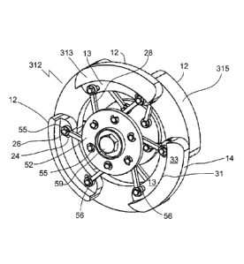
12 may lie
internally to the loops 56. An example of a pipe pig 312 with this feature is
shown in Figs. 15
and 16. Referring to Fig. 16, in this embodiment, the distance between leading
arcuate
cleaning elements 313 and trailing arcuate cleaning elements 315 is reduced,
and the leading
and trailing elements may even lie contiguously to one another. As before, the
adjacent
arcuate cleaning elements have corresponding slits 24 connected directly by
pins 26.
CA 02732387 2011-01-28
WO 2010/012087 PCT/CA2009/001056
13
Reducing the distance between adjacent elements 12 may make the radial pipe
pig 60
narrower and easier to move around bends. Also, this internal configuration of
arcuate
cleaning elements may be advantageous with multiple radial pipe pigs connected
in a train.
Referring to Figs. 16 and 18, the trailing elements 315 may also lie
internally to loops 56.
Referring to Fig. 23, an embodiment is shown where the trailing elements 317
of pipe pig
10A lie external to loops 56 (not shown). Referring to Figs. 16 and 17, the
loops 56 may be
inset within an indented portion 13 of elements 12, thus allowing a reduction
in the axial
width of the pipe pig 312 without having to reduce the axial width 15 of the
elements 12.
100341 Referring to Fig. 17, plates 52 and 54 may be connected via a
torsion spring (not
shown), and may be spaced relative to one another using a spacer 53 (also
shown in Fig. 19).
Referring to Fig. 16, an axle, such as a bolt 59 and nut 61 (shown in Figs. 17
and 18), may
secure the plates 52 and 54 (shown in Fig. 17) together. Referring to Fig. 16,
pins 26 may be
secured within slits 24 using suitable elements such as spring or retainer
clips 55. In some
cases retainer clips 55 are advantageous over nuts as clips 55 may be less
easily loosened
during use. Also, nuts and bolts may seize up after multiple compressions. It
is understood
that there are many suitable styles of retainer clips that may be used for
this purpose.
Referring to Fig. 21, a suitable pin 26 for use with a retainer clip (not
shown) may have a clip
indent 57 at each end for a retainer clip to snap into. Referring to Fig. 16,
one or more of a
larger loop 56 or washers (not shown) between loops 56 and elements 12 may be
used in
order to facilitate compression. Various spacers (not shown) on the pins 26
between the levers
28 and elements 12 or plates 52 may be present
[0035] Refering to Figs. 12, 16, and 17, the expandable circumference 14
may have an
outward taper 33 from a leading edge 31 of the expandable circumference 14.
Referring to
Fig. 23, at least the leading arcuate elements 12A in a pipe pig may
incorporate this feature.
This allows the pipe pig to navigate narrower portions of pipe, such as when
passing over a
weld bead or a tight bend, without jamming in the pipe. Outward taper 33,
which may be a 45
degree taper, may also function as a pressure responsive element in
coordination with the
respective plates as longitudinal pressure against the taper 33 is converted
into radial
compression pressure.
[0036] Various different combinations of pipe pigs may be connected in
series, for
CA 02732387 2011-01-28
WO 2010/012087
PCT/CA2009/001056
14
example, a radial pipe pig 60 (Fig. 12) may be connected in series to a pipe
pig 10 (Fig. 1).
Also, more than two pigs may be connected to create a series of pigs.
[0037] In some
embodiments, the elements 12 do not to have a sharp leading edge at the
largest outer circumference of the pipe pig, in order to prevent fracturing
when colliding with
weld beads during travel.
[0038] Table 1
shows the density, yield strength, ultimate strength and the yield strength-
to-density ratios of various steels and titanium alloys. Most materials have
temperature
limitations or high densities that make them unsuitable for use as a pipe pig.
In some
applications titanium alloys with an a or a+13 structure and precipitation
hardened stainless
steels are suitable for use at temperatures of 400¨ 500 C. The strength and
elastic modulus is
equivalent for titanium and precipitation hardened stainless steel. Table 1
shows Ti-6A1-4V,
which is an cc+13 titanium alloy that is commercially available in the form of
sheet or wire.
TABLE 1
Density 0-0.2 t /TS' Yield
Materials (gicm3) (MP a) (MPa) strength-to
density ratio
Martensitic stainless steels 7.9 380-600 420-700 4.8 ¨ 7.8
Austenitic stainless steels 7.9 210-350 400-700 2.6 ¨ 4.4
Precipitation hardened 7.9 900-1100 1100-1400 11.3 ¨ 13.7
stainless steels
Ti-6A1-4V 4.7 550 700 12.0
[0039] Materials
for the structural components, such as the spring element and the levers,
of the pipe pig shown in the various embodiments may be, for example,
precipitation
hardened stainless steels or titanium alloys with an cc or oc +13 structure,
for example Ti-6A1-
4V. Cheaper alternatives to titanium alloys, such as 17-7PH stainless steel,
are commercially
available spring alloys that have similar strength-to-density ratios as
titanium alloys. Other
materials with a similar or higher strength to weight ratio and elasticity may
also be used
depending on the application. Other materials, such as shape memory alloys,
may become
CA 02732387 2011-01-28
WO 2010/012087 PCT/CA2009/001056
more suitable when alloys are developed with high temperature functionality.
In an
embodiment made from suitable materials, such as Ti-6A1-4V or 17-7PH stainless
steel
structural and spring materials, the weight of the pig may be no more than
180g.
[0040] The arcuate cleaning elements shown in the various embodiments may
be
constructed from a material that is compatible with the operating fluid as the
arcuate cleaning
elements are subjected to some degree of wear from operation of the fluid. In
the case of a
heater in a refinery, the scraping edges of the pig are chosen to be hard
enough to remove the
coke from the tubing surface without damaging the underlying material. CCCs
may be used as
material for the arcuate cleaning elements. CCCs have a high strength to
density ratio,
acceptable wear resistance and present no contamination problems. Also, the
low hardness of
carbon materials may reduce the wear damage to the pipe material, such as for
example steel,
underlying the coke deposit. Other materials with similar properties may also
be used for the
arcuate cleaning elements.
[0041] Referring to Fig. 22, an exemplary cleaning element 12 has an
arcuate body 320
having a scraping edge 16 on an outer circumferential surface 322 of the
arcuate body 320.
One of the axial slits 24A is near an end 25A of an arc defined by the arcuate
body 320, and
another of the axial slits 24B is near the other end 25B of the arc, the axial
slits 24 being for
receiving sliding pin joints (not shown).
[0042] Although six arcuate cleaning elements are shown in Figs. 1 ¨3,
various other
numbers of arcuate cleaning elements may be used in other embodiments. The six
arcuate
cleaning elements are symmetrical in orientation. That is, the arcuate
cleaning elements have
centers that are separated by intervals of 360 / 6 = 60 degrees around the
expandable
circumference 14. In other embodiments in which the pipe pig has a number N of
arcuate
cleaning elements, the arcuate cleaning elements may have centers that are
separated by
intervals of 360 / N degrees around the expandable circumference.
[0043] Additional sets of arcuate cleaning elements may be added to the pig
design, for
example two sets of arcuate cleaning elements may be used as shown in Fig. 4.
More than two
sets of arcuate cleaning elements may also be used. In some embodiments the
arcuate
cleaning elements may be embedded within one another. In some embodiments the
arcuate
cleaning elements may form a spiral shape, with each successive linked arcuate
cleaning
CA 02732387 2011-01-28
WO 2010/012087 PCT/CA2009/001056
16
element lying closer to the inlet of the pipe than the previous element. In an
embodiment the
spiral shaped arcuate cleaning elements may connect between two sets of
circular arcuate
cleaning elements.
[0044] The spring element shown in the various embodiments may be any
element with
elastic properties. The spring element may also connect the arcuate cleaning
elements together
directly, for example, with a spring element connecting each linked pair of
arcuate cleaning
elements together. In some embodiments the pressure plates may be various
different shapes
provided that the pressure plate is responsive to pressure in the pipe. The
pressure plate may
be, for example, annular, circular, or a regular polygon. The diameter of the
expandable
circumference in the various embodiments may be adapted for different sizes of
pipe.
Frequent pigging, for example once every I ¨ 10 days, helps prevent
contamination such as
dense coke formation in the pipe.
[0045] The pipe cleaning pig may be used to clean other types of deposits
from pipes. For
example, a possible use for the pipe pig is the cleaning of pipes in a milk or
chocolate
processor, where the temperature is lower. The materials for the arcuate
cleaning elements,
the spring element and the frame elements may be chosen according to
characteristics of the
particular application. For example, materials for use in a low temperature
application may
have lower temperature limits. Also, cleaning materials used to clean other
types of deposits
may be chosen according to the hardness of the material being cleaned and the
adhesive
strength of the deposit. For example, softer deposits, such as hardened milk
or chocolate
products, may be cleaned with material with lower hardness characteristics
than the materials
used to cleaning coking deposits.
[0046] Immaterial modifications may be made to the embodiments described
here without
departing from what is covered by the claims.
[0047] In the claims, the word "comprising" is used in its inclusive sense
and does not
exclude other elements being present. The indefinite article "a" before a
claim feature does
not exclude more than one of the feature being present. Each one of the
individual features
described here may be used in one or more embodiments and is not, by virtue
only of being
described here, to be construed as essential to all embodiments as defined by
the claims.