Note: Descriptions are shown in the official language in which they were submitted.
CA 02732469 2011-02-23
SYSTEM AND METHOD FOR TRANSFERRING POWER TO INTRABODY
INSTRUMENTS
BACKGROUND
Technical Field
[00021 The present disclosure relates to a surgical robotic instrument for
performing
surgery of the minimally invasive type on a human body to be operated upon
and, more
particularly, to a system and method for transferring power to the surgical
robotic instrument.
Background of Related Art
[00031 Minimally invasive surgical procedures typically employ small incisions
in body
cavities for access of various surgical instruments, including forceps,
laparoscopes, scalpels,
scissors, and the like. It is often the case that several surgical hands, such
as several laparoscopic
instrument and camera holders, are necessary to hold these instruments for the
operating surgeon
during the particular surgical procedure. With the introduction of robotic-
assisted minimally
invasive surgery (MIS) in recent years, hospitals worldwide have made
significant investments
in acquiring this latest technology for their respective facilities.
[00041 Thus, it is known to use MIS when carrying out surgical operations.
When
surgery of this kind is performed, access to a subcutaneous surgical site is
provided via a number
(typically 3 to 5) of small (typically 5-12 mm) incisions, through which a
surgical arm is
1
CA 02732469 2011-02-23
manually passed. The surgical arms are then coupled to the surgical robotic
instrument, which is
capable of manipulating the surgical arms for performing the surgical
operations, such as
suturing or thermally cutting through tissue and cauterizing blood vessels
that have been cut
through. The surgical arms thus extend through the incisions during the
surgery, one of which
incisions is used for supplying a gas, in particular carbon dioxide, for
insufflating the
subcutaneous area and thus create free space at that location for manipulating
the surgical
instruments.
[00051 Open surgeries often require a surgeon to make sizable incisions to a
patient's
body in order to have adequate visual and physical access to the site
requiring treatment. The
application of laparoscopy for performing procedures is commonplace.
Laparoscopic surgeries
are performed using small incisions in the abdominal wall and inserting a
small endoscope into
the abdominal cavity and transmitting the images captured by the endoscope
onto a visual
display. The surgeon may thus see the abdominal cavity without making a
sizable incision in the
patient's body, reducing invasiveness and providing patients with the benefits
of reduced trauma,
shortened recovery times, and improved cosmetic results. In addition to the
endoscope,
laparoscopic surgeries are performed using long, rigid tools inserted through
incisions in the
abdominal wall.
[0006] However, conventional techniques and tools for performing laparoscopic
procedures may limit the dexterity and vision of the surgeon. Given the size
of the incisions, the
maneuverability of the tools is limited and additional incisions may be
required if an auxiliary
view of the surgical site is needed. Thus, robotic instruments may be used to
perform
laparoscopic procedures. However, conventional robotic instruments are not
continuously
connected to external power sources for receiving a steady stream of power.
CA 02732469 2011-02-23
SUMMARY
[0007] In accordance with the present disclosure, a power transfer system is
provided.
The system includes a power transmitting unit for transmitting power and a
power receiving unit
for receiving power from the power transmitting unit. The power transmitting
unit is positioned
outside a human body and the power receiving unit is located on an intrabody
instrument adapted
to be movable from the outside of the human body to inside the human body.
[0008] In one embodiment, the power transmitting unit is connected to an
energy source
and the intrabody instrument includes at least an energy storage unit and one
or more electronic
components.
[0009] In yet another embodiment, the intrabody instrument is a medical
instrument used
in surgical procedures and in another embodiment the intrabody instrument is a
robotic arm.
[0010] In still another embodiment, the power transmitting unit wirelessly
transfers
power to the power receiving unit in a continuous, non-interrupted manner. The
power may be
wirelessly transferred by using inductive coupling power transfer
methodologies or the power
may be wirelessly transferred by using radio frequency (RF) power transfer
methodologies.
[0011] In another embodiment, if an energy source connected to the power
transmitting
unit is disconnected, the power receiving unit is automatically energized via
an energy storage
unit located within the intrabody instrument.
[0012] In yet another embodiment, the system further includes one or more data
communications units for transferring data between the power transmitting unit
and the power
receiving unit. Additionally, the system further includes one or more data
communications units
for transferring data to one or more external sources or external control
units.
3
CA 02732469 2011-02-23
[00131 A method for transferring power is also provided in accordance with the
present
disclosure. The method includes providing a power transfer system as described
above. The
method further includes transmitting power via a power transmitting unit and
receiving power
from the power transmitting unit via a power receiving unit. The power
transmitting unit is
positioned outside a human body and the power receiving unit is located on an
intrabody
instrument adapted to be movable from the outside of the human body to inside
the human body.
[00141 In accordance with the present disclosure, a power transfer system is
provided for
wirelessly, continuously, and non-interruptedly transferring information. The
system includes a
transmitting unit connected to an energy source, the transmitting unit
configured to transmit the
information and a receiving unit including an energy storage unit and one or
more electronic
components, the receiving unit configured to receive the information from the
transmitting unit.
The transmitting unit is positioned outside a human body and the receiving
unit is operatively
associated with a robotic arm adapted to be movable from the outside of the
human body to one
or more positions inside the human body during surgical procedures.
BRIEF DESCRIPTION OF THE DRAWINGS
[00151 Various embodiments of the presently disclosed robotic instrument are
described
hereinbelow with references to the drawings, wherein:
[0016] FIG. 1 is a block diagram of a power transfer system, in accordance
with the
present disclosure;
100171 FIG. 2 is a block diagram of an information transfer system, in
accordance with
the present disclosure; and
[00181 FIG. 3 is a flowchart illustrating power transfer between a
transmitting unit and a
receiving unit, in accordance with the present disclosure.
4
CA 02732469 2011-02-23
DETAILED DESCRIPTION OF THE EMBODIMENTS
[0019] A more particular description of the present disclosure, briefly
summarized above,
may be had by reference to the embodiments of the present disclosure described
in the present
specification and illustrated in the appended drawings. It is to be noted,
however, that the
specification and appended drawings illustrate only certain embodiments of
this present
disclosure and are, therefore, not to be considered limiting of its scope. The
present disclosure
may admit to equally effective embodiments.
[0020] Reference will now be made in detail to exemplary embodiments of the
present
disclosure. While the present disclosure will be described in conjunction with
these
embodiments, it is to be understood that the described embodiments are not
intended to limit the
present disclosure solely and specifically to only those embodiments. On the
contrary, the
present disclosure is intended to cover alternatives, modifications, and
equivalents that may be
included within the spirit and scope of the present disclosure as defined by
the attached claims.
[0021] It has been found that in some cases, if not in most cases, performing
MIS
procedures by means of a surgical robotic instrument has advantages in
comparison with
manually performed MIS. Such a surgical robotic instrument may comprise a so-
called master,
which may be controlled by a surgeon, and a so-called slave, being the
surgical robotic
instrument that performs the surgery in response to commands from the master,
with a control
system providing the required connection between the master and the slave. The
slave robotic
instrument may comprise surgical arms, each configured as a long narrow bar,
at the distal end of
which a small instrument may be provided, which instrument, just like the
associated surgical
arm, may be manipulated and controlled from the master. Such instruments may
consist of, for
CA 02732469 2011-02-23
example, thermal cutters, scissors, suturing tools, but also of an endoscope,
by means of which
the surgical site may be shown to the surgeon at the location of the master.
[0022] Furthermore, in robotically-assisted or telerobotic surgery, the
surgeon typically
operates a master controller to remotely control the motion of surgical
instruments affixed to
robotic arms positioned at the surgical site. The master controller may be in
a location that may
be remote from the patient (e.g., across the operating room, in a different
room or a completely
different building from the patient). The master controller usually includes
one or more hand
input devices, which are coupled to the robotic arms holding the surgical
instruments, and the
master controller controls servo motors associated with the robotic arms for
articulating the
instruments at the surgical site. During the operation, the hand devices
provide mechanical
articulation and control of a variety of surgical instruments, coupled to the
robotic arms, that
each perform various surgical functions for the surgeon. The exemplary
embodiments of the
present disclosure may refer to manually operated medical instruments or
remotely operated
medical instruments. The medical instruments may be a robotic arm or connected
to a robotic
arm. The medical instruments may be incorporated within the robotic arm or may
be attached to
the robotic arm. One skilled in the art may contemplate a plurality of
different robotic systems
and/or configurations, not limited to robotic arms for achieving the
data/power transfer
capabilities described herein.
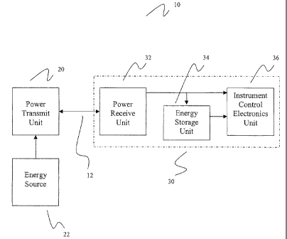
[0023] With reference to FIG. 1, a block diagram of a power transfer system,
in
accordance with the present disclosure is presented. The system 10 includes a
power transmit
unit 20 in operable communication with a medical instrument 30 (or intrabody
instrument). The
medical instrument 30 may be a robotic arm. The power transmit unit 20 may be
energized via
an energy source 22. The robotic arm 30 may include a power receive unit 32,
an energy storage
6
CA 02732469 2011-02-23
unit 34, and an instrument control electronics unit 36. The power transmit
unit 20 may
communicate, preferably in a wireless manner, with the power receive unit 32
of the robotic arm
30 via a communication link 12.
[0024] The power transmit unit 20 may be used for transmitting power and the
power
receive unit 32 may be used for receiving power from the power transmit unit
20. The power
transmit unit 20 may be positioned outside a human body and the power receive
unit 32 may be
located on an intrabody instrument (e.g., robotic arm 30) and may be adapted
to be movable
from the outside of the human body to inside the human body. The power
transmit unit 20 may
be connected to an energy source 22. The intrabody instrument 30 may include
at least an
energy storage unit 34 and an instrument control electronic unit 36. The
energy storage unit 34
may be a battery. The instrument control electronics unit 36 may include logic
controls and
intrabody instrument drivers.
[0025] Additionally, it is contemplated that a plurality of robotic arms may
be used, each
one having power receiving means, energy storage means, and/or control logic
means. The one
or more robotic instruments may be positioned entirely within the body cavity
of a human being
or patient. However, it is contemplated that the one or more robotic
instruments may be partially
inserted through a cavity of patient. It is also contemplated that the one or
more robotic arms
communicate with each other by sharing information. Also, controllers included
in the
instrument control electronics unit 36 may be purchased off-the-shelf,
constructed de novo, or
off-the-shelf controllers may be customized to control the robotic components
of the present
disclosure. One skilled in the art would be able to select a controller
appropriate for the robotic
instrument or intrabody instrument or the micro-robot.
7
CA 02732469 2011-02-23
[00261 In operation, the power transmit unit 20 preferably transmits power to
the power
receive unit 32 wirelessly. The power transmit unit 20 may wirelessly transfer
power to the
power receive unit 32 in a continuous, non-interrupted manner. The power may
be wirelessly
transferred by using inductive coupling power transfer methodologies, where
the inductive
coupling power transfer methodologies permit the power transmit unit 20 and
the power receive
unit 32 to share the same inductor-capacitor resonance frequency.
Alternatively, the power may
be wirelessly transferred by using radio frequency (RF) power transfer
methodologies, where the
RF power transfer methodologies permit the power transmit unit 20 and the
power receive unit
32 to operate at a common frequency.
[00271 When selecting a power supply, an external power supply may be employed
with
a tethered configuration. However, exemplary embodiments embrace that the
power be supplied
by batteries. Versions of the robotic instrument or intrabody instrument of
the present disclosure
may use alkaline, lithium, nickel-cadmium, or any other type of battery known
in the art.
Alternatively, magnetic induction may be another possible source of power, as
is piezoelectric
induced energy. In addition, one of skill in the art may adapt other power
sources such as
nuclear, fluid dynamic, solar or the like to power the robotic instrument or
intrabody instrument
of the present disclosure.
[00281 Wireless power transmission or wireless energy transfer is generally
the process
that takes place in system 10 where electrical energy may be transmitted from
a power source to
an electrical load, without interconnecting wires. The system 10 also includes
control logic that
may be capable of transferring power that may be received by the wireless
power-receiving
device 32 to the wireless power-transmitting device 20. The control logic may
be incorporated
8
CA 02732469 2011-02-23
within the instrument control electronics unit 36. Accordingly, the power
transfer system 10
disclosed herein may simultaneously receive and transmit power wirelessly.
[0029] For example, transmit circuitry (not shown) may produce an alternating
voltage,
having a predetermined frequency, from a direct current voltage supplied to
the transmit circuitry
during operation of the system 10 and supply the produced alternating voltage
to a transmit coil.
Also by way of example, the transmit circuitry may produce a predetermined
level of intensity of
an inductive field in a transmit coil. The control logic incorporated within
the instrument control
electronics unit 36 may comprise hardware alone (i.e., circuitry) or may
include both hardware
and software. The control logic incorporated within the instrument control
electronics unit 36
may be implemented by one of ordinary skill in the electronic arts. This
technology may
include, for example, application specific integrated circuits, a
microprocessor executing code
that may be designed to implement the functions and methods described herein,
programmable
logic arrays, etc. The control logic incorporated within the instrument
control electronics unit 36
may be capable of transferring power received by the wireless power-receiving
device 32 to the
wireless power-transmitting device 20. The control logic incorporated within
the instrument
control electronics unit 36 may transfer the power directly from the wireless
power-receiving
device 32 to the wireless power-transmitting device 20. For example, the
control logic may
supply the transmit circuitry with direct current voltage provided to the
control logic from the
receive circuitry.
[00301 In exemplary embodiments, a selectable power-transmitting protocol may
include,
for example, a particular frequency at which the transmit circuitry produces
an alternating
voltage that the transmit circuitry supplies to the transmit coil. Thus,
selecting a first power-
transmitting protocol may cause the transmit circuitry to produce an
alternating voltage at a
9
CA 02732469 2011-02-23
particular frequency and selecting a second power-transmitting protocol may
cause the transmit
circuitry to produce and alternating voltage at a different frequency.
Analogously, a particular
power-transmitting protocol may include, for example, a particular level of
intensity of an
inductive field for the transmitting coil. Thus, selecting a first power-
transmitting protocol may
cause the transmit circuitry to produce a particular level of intensity of the
inductive field,
whereas selecting a second power-transmitting protocol may cause the transmit
circuitry to
produce a different level of intensity for the inductive field.
100311 Additionally, the system 10 may have a settings mechanism, providing a
user of
the system 10 with a means for selecting parameters for the operation of the
system 10. The
settings mechanism may comprise, for example, a plurality of selectable
buttons with each
selectable button having a power-transmitting protocol associated with it.
Thus, the control logic
incorporated within the instrument control electronics unit 36 may be capable
of detecting when
one of the selectable buttons may be selected. The control logic may also be
capable of
operating the wireless power-transmitting device 20 in accordance with the
power-transmitting
protocol associated with the selected buttons. In this manner, a user of the
system 10 may
choose a particular power-transmitting protocol that is best suited for a
particular surgical
procedure to be performed. For example, some surgical procedures may require
more power to
be consumed by the robotic instrument or intrabody instrument than other
surgical procedures.
As a result, a user of the system 10 may be able to control the amount of
power transferred from
the power transmit unit 20 to the power receive unit 32 by selecting a desired
protocol.
100321 Moreover, the power transmit unit 20 may be configured to transmit each
of a
plurality of different power levels via a respective one of a plurality of
different frequency
signals. For example, the power transmit unit 20 may transmit a low-power
wireless
CA 02732469 2011-02-23
transmission on a particular frequency to initially power up basic components
of the system 10
for initial communications. The particular frequency at which the power
transmit unit 20
transmits the low-level minimum power may be a fixed, pre-selected frequency
signal that any of
the robotic instruments may access. Additionally or alternatively, the
transmitting unit may
transmit power wirelessly using an automatic channel selection technique or an
automatic
channel switching technique that enables the receiving unit to automatically
select a best channel
(e.g., a frequency associated with the least amount of interference) prior to
and during
transmission. In other words, the user of the system 10 may enter a code
relating a specific type
of surgery and the system 10 may automatically determine the required power to
be transmitted
from the power transmit unit 20 to the power receive unit 32.
(0033] Furthermore, the stored information may also be used to implement a
power
conservation routine in which the robotic instruments are powered down or
placed in a low-
power mode when full operation of the robotic instruments may not be required.
For example,
the robotic instruments may enter into a low-power mode when only partial
operation of the
robotic instruments may be required. Alternately, if the energy source 22
connected to the power
transmit unit 20 is disconnected, then the power receive unit 32 may be
automatically energized
via the energy storage unit 34 located within the intrabody instrument or
robotic arm 30.
[0034] Moreover, in the illustrated examples described above, the layout of a
process
control system may not be limited by the locations of wired power sources or
wired networks.
Instead, field devices and other elements of a process control system may be
located anywhere
and use wireless power transmissions to receive power and wireless data
communications to
exchange data with other process control system devices or apparatus. Wireless
power and data
11
CA 02732469 2011-02-23
also enables reconfiguring the layout of process control systems relatively
easier and quicker
because relatively fewer cables or wires need to be moved or installed to
relocate field devices.
[0035] In exemplary embodiments, the system 10 may also have a display
mechanism
(not shown) for providing a user with an indication of the operating status of
the system 10. The
display mechanism may include, for example, a power indicator (e.g., an LED)
that indicates to a
user that the system 10 is receiving power (see FIG. 2). The power indicator
may light up, for
example, when the wireless power-receiving device 32 of the system 10 is
receiving power.
Additionally, the power indicator may comprise a signal-strength meter,
allowing the user to
determine whether the signal transmitting the power is strong. The display
mechanism may also
include a battery-level indicator for the energy storage unit 34. The battery-
level indicator may
light up when the rechargeable battery (or energy storage unit 34) is fully
charged. In other
embodiments, a battery-level indicator may show approximately how much power
is in the
rechargeable battery (or energy storage unit 34). As a result, the user of the
system 10 may be
continuously informed or notified of the status of the power transferred from
the power transfer
unit 20 to the power receive unit 32.
[0036] With reference to FIG. 2, a block diagram of an information transfer
system, in
accordance with the present disclosure is presented. The system 40 includes a
transmit unit 50
and an intrabody instrument or robotic arm 60. The transmit unit 50 may be in
operable
communication with an energy source 52 and a storage unit 54. The robotic arm
60 may include
a receive unit 62, an energy storage unit 64, an instrument control
electronics unit 66, a storage
unit 68, and an LED indicating unit 70. The transmit unit 50 may communicate
with the receive
unit 62 of the robotic arm 60 via a communications link 42.
12
CA 02732469 2011-02-23
[0037} Of course, several different types of connection components or
communications
links may be used to connect the transmit unit 50 to the receive unit 62. As
used herein,
"connection component" may be intended to refer to a wired or wireless
connection between at
least two components of systems 10, 40 that provide for the transmission
and/or exchange of
information and/or power between components. A connection component may
operably couple
consoles/displays (not shown) and robotic instruments to allow for
communication between, for
example, power components of robotic instruments and a visual display on, for
example, a
console.
[0038) According to one embodiment, connection components may be wired
connections, such as a wire, cord, or other physical flexible coupling. The
wired connections
may be coupled at one end to robotic instrument and at a second end to, for
example, a
console/display. For purposes of this application, the physical or wired
connection may also be
referred to as "tethered" or "a tether." The wired connection may be any
physical component
that may be flexible, pliable, or otherwise capable of being easily formed or
manipulated into
different shapes or configurations.
[0039] The wireless connection may be referred to herein as "untethered." An
"untethered device," "wireless device," or "wireless connection" may be
intended for purposes
of this application to mean any robotic instrument that may be fully enclosed
within the patient's
body such that no portion of robotic instrument may be external to the
patient's body for at least
a portion of the surgical procedure or, alternatively, any robotic instrument
that operates within
the patient's body, even partially, while not being physically connected to
any external object for
at least a portion of the surgical procedure.
13
CA 02732469 2011-02-23
[0040] The storage units 54, 68 may include any desired type of volatile
and/or non-
volatile memory such as, for example, static random access memory (SRAM),
dynamic random
access memory (DRAM), flash memory, read-only memory (ROM), etc. The storage
units 54,
68 may include any desired type of mass storage device including hard disk
drives, optical
drives, tape storage devices, etc. The storage units 54, 68 may store
information related to a
plurality of different components within the transmit unit 50 and the robotic
arm 60. The
information stored in the storage units 54, 68 is further described below.
[0041] The LED indicating units 70 may inform or notify or indicate to the
user of
systems 10, 40 whether power is transferred between the transmit unit 50 and
the receive unit 62.
[0042] With reference to FIG. 3, a flowchart 80 illustrating power transfer
between a
transmitting unit and a receiving unit, in accordance with the present
disclosure is presented.
[0043] In step 82, information (data/power) may be transmitted to the one or
more
medical instruments via a transmitting unit. In step 84, the information may
be received by the
one or more medical instruments via the one or more receiving units. In step
86, the information
may be processed at the one or more medical instruments via the instruments
control electronics
unit, while the one or more medical instruments are moved into and out of a
human body. In
step 88, the updated information may be transmitted to the transmitting unit.
In step 90, the
updated information may be stored in a storage unit in operable communication
with the
transmitting unit. In step 92, one or more parameters of the one or more
medical instruments
may be adjusted in accordance with the updated information received from the
one or more
receiving units. The process then ends for the first cycle or first iteration.
However, the process
may be a continuous iterative process. In other words, the steps of the
process may repeat for a
number cycles or iterations, where parameters of the medical instruments are
constantly adjusted.
14
CA 02732469 2011-02-23
[0044] In an alterative embodiment, an operating room table would contain
electrical and
mechanical interfaces for several surgical robotic manipulators or arms or
instruments. The
robotic instruments may be remotely controlled by using a plurality of
consoles or external
sources (e.g., surgical workstations, personal computers, etc.) preferably
located away from the
operating room table, such as but not limited to within a hospital as
connected to a hospital local
network and/or a remote network, such as the Internet. The control consoles
may operate in
conjunction with the one or more robotic instruments that may be positioned in
a body cavity of
a human being or patient. That is, the control consoles may be used to operate
the one or more
robotic instruments inside the body cavity of the patient. As used herein,
"console" may be
intended to refer to a controller or operational hub. A plurality of visual
displays may be
connected to the plurality of consoles for providing visual feedback of the
body cavity as
captured by the one or more robotic instruments.
[0045] In one embodiment, the visual display may be a standard video monitor.
In an
alternative embodiment, the visual display may display two dimensional visual
feedback, three
dimensional visual feedback or stereoscopic imaging to a surgeon via an
imaging component on
the one or more robotic instruments. Those of ordinary skill in the art will
recognize that a
signal from a camera may be processed to produce a display signal for many
different types of
display devices, including, but not limited to: televisions configured to
display an NTSC
(national television system committee) signal, televisions con- figured to
display a PAL (phase
alternating line) signal, cathode ray tube based computer monitors, LCD
(liquid crystal display)
monitors, and plasma displays.
[0046] The robotic instruments may be connected to base stations (not shown)
that are
connected to the operating room tables. The base stations may include a data
signal connector
CA 02732469 2011-02-23
for receiving/transmitting data to and from the robotic instruments (e.g.,
camera signals, position
sensor signals, power signals, etc.), a control signal connector for
transmitting control signals
(and receiving feedback signals) to actuated components of the robotic
instruments (e.g., motors,
camera operation, etc.), and a power supply connector for supplying the
requisite electrical
and/or mechanical (e.g., pneumatic, hydraulic) power to actuated components of
the robotic
instruments. It is recognized that data, control signal, and power
requirements for robotic
instruments may vary depending upon the specific designed surgical task of the
robotic
instruments (e.g., high voltage vs. low voltage, number of actuators, tool
operational
requirements, etc.). Further, it is recognized that the physical dimensions,
strength, weight, and
stiffness of the base stations, and the connection therebetween are designed
to provide a stable
base for operation of the attached robotic instruments. Of course, the robotic
instruments may
not be connected to base stations connected to an operating table. The robotic
instruments may
be manually operated by, for example, a surgeon.
[00471 In an alternative embodiment, the robotic instruments may be in
communication
with a communication manager of the consoles via communication capabilities of
the base
stations. The base stations may be linked through a wire based connection to a
wired
communication link of the console. It is recognized that the connection and
the link may be in
an existing operating room communication infrastructure network, such that the
base stations
may be attached to an electrical/mechanical connection harness. It is
recognized that the
connection and link may be fully compatible with IP fiber optic network
protocols for connection
to the remote consoles for control of the robotic instruments via the base
stations. Each of the
base stations and/or robotic instruments may have assigned IP addresses to
facilitate
communication with the console via the communication manager. For example, IP
addresses
16
CA 02732469 2011-02-23
may be assigned to arm controllers in the controller unit. The network may
also include switches
and routers as is known in the art to enable communication with other
telecommunication
devices connected to the room network. Examples of the network protocols may
be such as but
not limited to Ethernet/IP and TCP/IP. However, as will be readily appreciated
by those having
ordinary skill in the art, any other suitable communication medium and
protocol could be used.
[0048] In yet another alternative embodiment, a computer may have software for
operating the robotic instruments. The computer may include a network
connection interface,
such as a wireless transceiver or a wired network interface card or a modem,
coupled via
connection to a device infrastructure. The connection interface may be
connectable during
operation of the console to the network. The network may support the
transmission of
data/signaling in network messages between consoles and the robotic system.
The consoles may
also have a user interface (including hand controllers), coupled to the device
infrastructure by
connection, to interact with a user (e.g., surgeon). The user interface may
include one or more
user input devices such as but not limited to a keyboard, a keypad, a track
wheel, a stylus, a
mouse, a microphone and the user output device such as a display screen and/or
a speaker. If the
screen is touch sensitive, then the display may also be used as the user input
device as controlled
by the device infrastructure. The user interface may be employed by the user
of the console to
coordinate messages or instructions over the network for operation of the
robotic instruments.
10049] Operation of the console may be enabled by the device infrastructure.
The device
infrastructure may include a computer processor and a memory module/unit. The
computer
processor may manipulate the operation of the network interface and the user
interface by
executing related instructions, which are provided by an operating system and
the software.
Further, it is recognized that the device infrastructure may include a
computer readable storage
17
CA 02732469 2011-02-23
medium coupled to the processor for providing instructions to the processor
and/or to
load/update the software in the memory module. The computer readable medium
may include
hardware and/or software such as, by way of example only, magnetic disks,
magnetic tape,
optically readable medium such as CD/DVD ROMS, and memory cards. In each case,
the
computer readable medium may take the form of a small disk, floppy diskette,
cassette, hard disk
drive, solid state memory card, or RAM provided in the memory module. It
should be noted that
the above listed example computer readable mediums may be used either alone or
in
combination.
[00501 In yet another alternative embodiment, a number of information managers
may be
used to control and manipulate the information. A communication manager may
provide for
communication of data signals to/from the data manager and communication of
control signals
to/from the control manager. A database manager may provide for such as but
not limited to
access of image data to/from an image database, data related to the
functioning/set-up of various
elements of the robotic instruments, and various posit] on/orientation sensor
data, and for
providing data as needed to the position and orientation manager. A control
manager may
provide for monitoring the operation of the robotic instruments. A
position/orientation manager
may be responsible for such as but not limited to receiving sensor data from
the data manager for
calculating the position and orientation of the robotic instruments. A
calculated
position/orientation information manager may be made available to such as but
not limited to the
actuation of the display manager and the control manager. A configuration
manager may
provide for such as but not limited to dynamic configuration of the robotic
instruments for a
particular surgical procedure. The dynamic configuration may be automatic,
semi-automatic,
and/or manual operator intervention. A display manager of the software may
coordinate/render
18
CA 02732469 2011-02-23
the calculated position/orientation information and the patient/tool images on
a display of a
console of the user interface, as directed by the operator, for example, a
surgeon.
[0052] In one implementation, by positioning robotic instrument within a body
cavity
relative to console, the power transfer system 10 may allow the surgeon to
determine and
maintain spatial orientation of robotic instrument with respect to the one or
more consoles.
Other benefits of system 10 may include, but are not limited to: providing a
training tool for
surgeons, reducing or eliminating the need for a surgeon to be on-site, and
reducing the cost of
robotic surgical systems.
[0052] In yet another exemplary embodiment, two or more robotic instruments
may be
operably coupled to each other as well as to an external unit (e.g., a
console, or personal
computer or network, etc.). According to one embodiment in which there are two
robotic
instruments, the two robotic instruments may be operably coupled to each other
and an external
unit by a flexible wired connection or a wireless connection. That is, the two
robotic instruments
may be operably coupled to each other by a flexible wired connection that may
be coupled to
each robotic instrument and each robotic instrument may also be operably
coupled to an external
unit by a flexible wired connection.
[0053] In summary, the present disclosure facilitates the application of
laparoscopy and
other minimally invasive surgical techniques to a much wider range of
procedures by providing
semi-autonomous and autonomous manually or remotely controlled robotic
instruments that are
used inside the body, especially human bodies. The present disclosure provides
robotic in vivo
wired and wireless manipulator, imaging, power, and sensor devices that may be
inserted in the
area to be treated, for example, the abdomen. The devices overcome the
limitations associated
with current generation laparoscopic cameras and tools, providing the surgical
team a view of the
19
CA 02732469 2011-02-23
surgical field from multiple angles, in vivo patient monitoring capability,
and in vivo
manipulator dexterity, as well as power control capabilities. It is
contemplated that the instant in
vivo robot could help the surgeon directly manipulate tissue. It is also
contemplated to
continuously and non-interruptedly provide power capabilities to the robotic
devices. In other
words, it is contemplated to continuously and wirelessly transfer power from
the outside of the
patient to any robotic intrabody instrument. Thus, unlike known systems that
require field
device power (e.g., alternating current (AC) power or direct current (DC)
power) to be provided
via electrical wires or cables and/or via a battery, the example systems and
methods described
herein may be used to implement field devices (e.g., a temperature sensor, a
pressure sensor, a
status (open/closed) sensor, an actuator, a power sensor, etc.) in a process
control system that
operate using wirelessly transmitted power and that communicate wirelessly
within the process
control system.
[00541 From the foregoing and with reference to the various figure drawings,
those
skilled in the art will appreciate that certain modifications may also be made
to the present
disclosure without departing from the scope of the same. While several
embodiments of the
disclosure have been shown in the drawings, it is not intended that the
disclosure be limited
thereto, as it is intended that the disclosure be as broad in scope as the art
will allow and that the
specification be read likewise. Therefore, the above description should not be
construed as
limiting, but merely as exemplifications of particular embodiments. Those
skilled in the art will
envision other modifications within the scope and spirit of the claims
appended hereto.