Note: Descriptions are shown in the official language in which they were submitted.
CA 02732853 2011-02-02
WO 2010/017642 PCT/CA2009/001138
STEREOTACTIC DRIVE SYSTEM
BACKGROUND OF THE INVENTION
[0001] The present invention relates generally to control systems.
More specifically, the present invention relates to a drive system for
controlling the longitudinal movement and rotational position of an
elongate member.
[0002] Each year roughly 200,000 patients are diagnosed with brain
tumors in the United States. Roughly 17,000 of these tumors are "benign,"
meaning that the tumor mass is not cancerous. However, the other
roughly 183,000 of these tumors are "malignant" (i.e., cancerous),
meaning that they are capable of causing or contributing to patient death.
Approximately 10% of cancerous brain tumors are "primary" tumors,
meaning that the tumors originate in the brain. The primary tumors
typically consist of brain tissue with mutated DNA that aggressively grows
and displaces or replaces normal brain tissue. The most common of the
primary tumors are known as gliomas, which indicate cancer of the glial
cells of the brain. In most instances, primary tumors appear as single
masses. However, these single masses can often be quite large,
irregularly-shaped, multi-lobed and/or infiltrated into surrounding brain
tissue.
[0003] Primary tumors are generally not diagnosed until the patient
experiences symptoms, such as headaches, altered behavior, sensory
impairment, or the like. However, by the time the symptoms develop the
tumor may already be large and aggressive.
[0004] One well known treatment for cancerous brain tumors is
surgery. In particular, surgery involves a craniotomy (i.e., removal of a
portion of the skull), dissection, and total or partial tumor resection. The
objectives of surgery include removal or lessening of the number of active
malignant cells within the brain, and a reduction in the pain or functional
impairment due to the effect of the tumor on adjacent brain structures.
-1-
CA 02732853 2011-02-02
WO 2010/017642 PCT/CA2009/001138
However, by its very nature, surgery is highly invasive and risky.
Furthermore, for some tumors surgery is often only partially effective. In
other tumors, the surgery itself may not be feasible, it may risk impairment
to the patient, it may not be tolerable by the patient, and/or it may involve
significant cost and recovery.
[0005] Another well known treatment for cancerous brain tumors is
stereotactic radiosurgery (SRS). In particular, SRS is a treatment method
by which multiple intersecting beams of radiation are directed at the tumor
such that the point of intersection of the beams receives a lethal dose of
radiation, while tissue in the path of any single beam remains unharmed.
SRS is non-invasive and is typically performed as a single outpatient
procedure. However, confirmation that the tumor has been killed or
neutralized is often not possible for several months post-treatment.
Furthermore, in situations where high doses of radiation may be required
to kill a tumor, such as in the case of multiple or recurring tumors, it is
common for the patient to reach the "toxic threshold" prior to killing all of
the tumors, where further radiation is inadvisable.
[0006] More recently, the treatment of tumors by "heat" (also referred
to as hyperthermia or thermal therapy) has been developed. In particular,
it is known that above 57 C all living tissue is almost immediately and
irreparably damaged and killed through a process called coagulation
necrosis or ablation. Malignant tumors, because of their high
vascularization and altered DNA, are more susceptible to heat-induced
damage than normal tissue. Various types of energy sources may be
used, such as laser, microwave, radiofrequency, electric, and ultrasound
sources. Depending upon the application and the technology, the heat
source may be extracorporeal (i.e., outside the body), extrastitial (i.e.,
outside the tumor), or interstitial (i.e., inside the tumor).
[0007] Interstitial thermal therapy (ITT) is a process designed to heat
and destroy a tumor from within the tumor. One advantage of this type of
therapy is that the energy is applied directly to the tumor rather than
passing through surrounding normal tissue. Another advantage of the
-2-
CA 02732853 2011-02-02
WO 2010/017642 PCT/CA2009/001138
type of therapy is that the energy deposition is more likely to be extended
throughout the entire tumor.
[0008] One exemplary ITT process begins by inserting an optical fiber
into the tumor, wherein the tumor has an element at its "inserted" end that
redirects laser light from an exterior source in a direction generally at
right
angles to the length of the fiber. The energy from the laser thus extends
into the tissue surrounding the end or tip and effects heating. The energy
is directed in a beam confined to a relatively shallow angle so that, as the
fiber is rotated, the beam also rotates around the axis of the fiber to effect
heating of different parts of the tumor at positions around the fiber. The
fiber can thus be moved longitudinally and rotated to effect heating of the
tumor over the full volume of the tumor with the intention of heating the
tumor to the required temperature without significantly affecting the
surrounding tissue.
[0009] The fiber used in the ITT process may be controlled and
manipulated by a surgeon with little or no guidance apart from the
surgeon's knowledge of the anatomy of the patient and the location of the
tumor. Therefore, it is difficult for the surgeon to effect a controlled
heating
which heats the entire tumor to a required level while also minimizing
damage to the surrounding tissue.
[0010] It is known that the location of tumors and other lesions to be
excised can be determined using a magnetic resonance imaging system.
Although these imaging systems have been helpful to assist the surgeon
in determining a location of the tumor to be excised, use of the imaging
systems ended once the location of the tumor was mapped out for the
surgeon. In particular, previous excision procedures required the removal
of the patient from the imaging system prior to commencing treatment.
However, movement of the patient, together with the partial excision or
coagulation of some of the tissue, can significantly change the location of
the tumor to be excised. As a result, any possibility of providing controlled
accuracy in the excision is eliminated.
-3-
CA 02732853 2011-02-02
WO 2010/017642 PCT/CA2009/001138
[0011] It is also known that magnetic resonance imaging systems can
be used by modification of the imaging sequences to determine the
temperature of tissue within the image and to determine changes in that
temperature over time.
[0012] U.S. Pat. No. 4,914,608 (LeBiahan) assigned to U.S.
Department of Health and Human Services issued Apr. 3, 1990, discloses
a method for determining temperature in tissue.
[0013] U.S. Pat. No. 5,284,144 (Delannoy) also assigned to U.S.
Department of Health and Human Services and issued Feb. 8, 1994,
discloses an apparatus for hyperthermia treatment of cancer in which an
external, non-invasive heating system is mounted within the coil of a
magnetic resonance imaging system. The disclosure is speculative and
relates to initial experimentation concerning the viability of MRI
measurement of temperature in conjunction with an external heating
system. The disclosure of the patent has not led to a commercially viable
hyperthermic treatment system.
[0014] U.S. Pat. Nos. 5,368,031 and 5,291,890 assigned to General
Electric relate to an MRI controlled heating system in which a point source
of heat generates a predetermined heat distribution which is then
monitored to ensure that the actual heat distribution follows the predicted
heat distribution to obtain an overall heating of the area to be heated.
Again this patented arrangement has not led to a commercially viable
hyperthermia surgical system.
[0015] U.S. Pat. No. 4,671,254 (Fair) assigned to Memorial Hospital
for Cancer and Allied Diseases and issued Jun. 9, 1987, discloses a
method for the non surgical treatment of tumors in which the tumor is
subjected to shock waves. This type of treatment does not incorporate a
monitoring system to monitor and control the effect of the shock waves.
[0016] U.S. Pat. No. 5,823,941 (Shaunnessey), not assigned, and
issued Oct. 20, 1998, discloses a specially modified endoscope designed
to support an optical fiber. The optical fiber emits light energy and may be
-4-
CA 02732853 2011-02-02
WO 2010/017642 PCT/CA2009/001138
moved longitudinally and rotated angularly about its axis to direct the
energy. The device is used for excising tumors, and the energy is
arranged to be sufficient to effect vaporization of the tissue to be excised.
The gas formed during the process is removed by suction through the
endoscope. An image of the tumor is obtained by MRI, which is thereafter
used to program a path of movement of the fiber to be taken during the
operation. Again, there is no feedback during the procedure to control the
movement of the optical fiber, and the operation is wholly dependent upon
the initial analysis. This arrangement has not achieved commercial or
medical success.
[0017] U.S. Pat. No. 5,454,807 (Lennox) assigned to Boston Scientific
Corporation and issued Oct. 3, 1995, discloses a device for use in
irradiating a tumor with light energy from an optical fiber. A cooling fluid
is
supplied through a conduit within the fiber to apply surface cooling and to
prevent surface damage while allowing increased levels of energy to be
applied to deeper tissues. Once again, this arrangement does not provide
feedback control of the heating effect.
[0018] U.S. Pat. No. 5,785,704 (Bille) assigned to MRC Systems
GmbH and issued Jul. 28, 1996, also discloses a particular arrangement of
a laser beam and lens for use in irradiation of brain tumors. In particular,
this arrangement uses high speed pulsed laser energy for a photo-
disruption effect, but does not disclose methods of feedback control of the
energy.
[0019] Kahn, et al. in Journal of Computer Assisted Tomography
18(4):519-532, July/August 1994; Kahn, et al. in Journal of Magnetic
Resonance Imaging 8: 160-164, 1998; and Vogl, et al. in Radiology 209:
381-385, 1998, all disclose a method of application of heat energy from a
laser through a fiber to a tumor where the temperature at the periphery of
the tumor is monitored during the application of the energy by MRI.
McNichols, RJ et al. in Lasers in Surgery and Medicine, 34:48-55, 2005,
disclose energy control by an MRI feedback monitoring arrangement in a
paper entitled "MR Thermometry-Based Feedback Control of LITT at 980
-5-
CA 02732853 2011-02-02
WO 2010/017642 PCT/CA2009/001138
nm." Additionally, the paper of Vogl discloses a cooling system supplied
commercially by Somatex of Berlin, Germany for cooling the tissues at the
probe end. The system is formed by an inner tube containing the fiber
mounted within an outer tube. Cooling fluid is passed between the two
tubes and inside the inner tube in a continuous stream.
[0020] While highly effective in certain applications, the use of ITT to
treat brain tumors has been limited by the inability to focus the energy
exclusively and precisely on the tumor so as to avoid damage to
surrounding normal brain tissue. This is complicated by the fact that many
brain tumors are highly irregular in shape.
[0021] Focused laser interstitial thermal therapy (f-LITT) is the next
general refinement of laser-based thermal therapy technologies. In
particular, f-LITT enables precise control over the deposition of heat
energy, thereby enabling the physician to contain cell damage exclusively
to within a tumor mass of virtually any size and shape. However, as with
other ITT treatment systems, there is a need for an apparatus that allows a
surgeon to precisely control the position of the treatment device within the
tumor mass.
[0022] Therefore, a heretofore unaddressed need exists to establish a
drive system for an elongate member that is capable of precisely
controlling both the longitudinal and rotational positions of the elongate
member with respect to a target, such as a tumor mass. Furthermore,
what is needed is a drive system for an elongate member that is simple to
use and that yields accurate and predictable results. The drive system
should preferably be structured for use with any elongate medical device
including, but not limited to, laser probes, catheters, endoscopes, and the
like. The drive system should also preferably be manufactured from
materials that make the system MRI-compatible.
SUMMARY OF THE INVENTION
[0023] The present invention solves the foregoing problems by
providing a drive system for controlling movement of an elongate member
-6-
CA 02732853 2011-02-02
WO 2010/017642 PCT/CA2009/001138
including a base unit having a first rotatable knob and a second rotatable
knob, a follower assembly including a follower slidably coupled to a guide
rail, a longitudinal movement wire, and a rotational movement wire. The
follower includes a longitudinal movement pulley, a rotational movement
pulley, and an alignment element structured to receive an elongate
member such that the elongate member is attachable thereto. The
longitudinal movement wire operably couples the first rotatable knob to the
longitudinal movement pulley such that rotation of the first knob drives the
follower in a longitudinal direction along the guide rail. The rotational
movement wire operably couples the second rotatable knob to the
rotational movement pulley such that rotation of the second knob rotates
the alignment element and attached elongate member.
BRIEF DESCRIPTION OF THE DRAWINGS
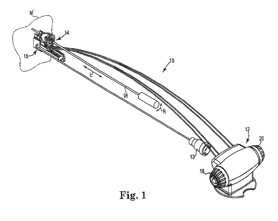
[0024] FIG. 1 is a perspective view of one exemplary drive system in
accordance with the present invention that includes a commander unit, a
follower assembly, and an elongate member coupled to the follower
assembly.
[0025] FIG. 2A is a perspective view of the commander unit and
follower assembly of FIG. 1 illustrating rotation of a first knob to cause
longitudinal movement of a follower device.
[0026] FIG. 2B is a perspective view of one exemplary alternative
follower assembly in accordance with the present invention.
[0027] FIG. 3 is a perspective view of the commander unit and follower
assembly of FIG. 1 illustrating rotation of a second knob to cause
rotational movement of an alignment device on a proximal end of the
follower device.
[0028] FIG. 4 is an enlarged perspective view of the commander unit
with a commander cover removed to illustrate the internal components of
the commander unit.
-7-
CA 02732853 2011-02-02
WO 2010/017642 PCT/CA2009/001138
[0029] FIG. 5 is a diagram illustrating a side view of a first tension
block assembly within the commander unit.
[0030] FIG. 6 is an enlarged perspective view of the follower assembly
with a portion of the follower device housing removed in order to illustrate
the internal components of the follower device.
[0031] FIG. 7 is a perspective view of the drive system in accordance
with the present invention wherein the follower device is shown in a
"neutral" starting position.
[0032] FIG. 8A is a perspective view of the drive system illustrating
operation of the commander unit to drive the follower device longitudinally
and in a distal direction.
[0033] FIG. 8B is a diagram of an underside of the follower assembly
illustrating movement of the follower device longitudinally and in the distal
direction shown in FIG. 8A.
[0034] FIG. 9A is a perspective view of the drive system illustrating
operation of commander unit to drive the follower device longitudinally and
in a proximal direction.
[0035] FIG. 9B is a diagram of the underside of the follower assembly
illustrating movement of the follower device longitudinally and in the
proximal direction shown in FIG. 9A.
[0036] FIG. 10 is a perspective view of the drive system illustrating
operation of the commander unit to rotate the alignment device in a
clockwise direction as viewed from a proximal end of the follower device.
[0037] FIG. 11 is a perspective view of the drive system illustrating
operation of the commander unit to rotate the alignment device in a
counterclockwise direction as viewed from the proximal end of the follower
device.
[0038] FIG. 12A is a diagram illustrating the structure of a first locking
device coupled to the commander unit.
-8-
CA 02732853 2011-02-02
WO 2010/017642 PCT/CA2009/001138
[0039] FIG. 12B is a perspective view of the first locking device
illustrating the first knob in an unlocked position.
DETAILED DESCRIPTION OF THE INVENTION
[0040] The present invention involves a drive system for stereotactic
positioning of an elongate member. The elongate member may include,
for example, elongate probes, catheters, endoscopes, and the like.
However, those skilled in the art will appreciate that the drive system of the
present invention may be used in conjunction with any elongate member
requiring precise control in a longitudinal and/or rotational direction.
[0041] In one exemplary embodiment, the drive system in accordance
with the present invention may be used to control the precise movement of
a laser probe insertable into the skull of a patient for the treatment of
tumors. In particular, and as will be evident to one skilled in the art based
upon the following disclosure and corresponding figures, the drive system
may be operated to position a distal end of a probe at precise locations
within the tumor through both controlled longitudinal and rotational
movement of the probe.
[0042] Referring now to FIG. 1, there is shown a perspective view of
one exemplary drive system 10 including commander or base unit 12,
follower assembly 14, potentiometer assembly 15 having connector 13,
and elongate member 16 coupled to follower assembly 14. As will be
described in further detail to follow, commander unit 12 has a first knob 18
structured for causing longitudinal movement of elongate member 16 as
indicated by arrow L, and a second knob 20 structured for causing
rotational movement of elongate member 16 as indicated by arrow R.
Thus, as those skilled in the art will appreciate, drive system 10 may be
utilized to control the precise longitudinal and angular position of elongate
member 16 relative to or within a particular location or element, such as
generic mass M shown in broken lines proximate to follower assembly 14.
[0043] Potentiometer assembly 15 may be operably coupled to
follower assembly 14 and configured to provide feedback regarding the
-9-
CA 02732853 2011-02-02
WO 2010/017642 PCT/CA2009/001138
longitudinal and angular position of elongate member 16 to a computer
system or other processing means through connector 13. An external
display may be operably coupled to the computer system or processing
means in order to display longitudinal and rotational movement of elongate
member 16 during operation of drive system 10. A display may
alternatively be provided on commander unit 12 instead of (or in addition
to) the external display as will be appreciated by those skilled in the art.
In
one exemplary embodiment, the longitudinal movement of elongate
member 16 may be displayed as a numerical value (relative to a "zero"
reference point) having any suitable unit, such as in millimeters.
Furthermore, the rotational movement of elongate member 16 may be
displayed in any suitable manner, such as by a number in a range
between about +180 degrees and about -180 degrees surrounding a
"zero" reference point. However, those skilled in the art will appreciate
that the longitudinal and rotational movement of elongate member 16 may
be displayed in numerous other ways and within numerous other ranges
without departing from the intended scope of the present invention.
[0044] FIG. 2A is a perspective view of commander unit 12 and
follower assembly 14 illustrating rotation of first knob 18 and the
corresponding longitudinal movement of follower assembly 14. In
particular, commander unit 12 includes a commander base 19 and a
commander cover 21. Follower assembly 14 includes follower device 22
having a distal end 24 and a proximal end 26. Follower device 22 is
encased by follower housing 27 and is operably coupled to guide rail 28
such that follower device 22 may be driven between a distal end 29 and a
proximal end 31 of guide rail 28. Potentiometer assembly 15 is positioned
at distal end 29 of guide rail 28, and adjacent to potentiometer assembly
15 is attachment means 17 for attaching follower assembly 14 to any
suitable mount or support, such as an adjustable trajectory setting mount.
As illustrated in FIG. 2A, attachment means 17 includes a "clip" type
fastener structured to allow the attachment means to clip to a mount or
support, although any suitable attachment means may be used.
-10-
CA 02732853 2011-02-02
WO 2010/017642 PCT/CA2009/001138
[0045] Although follower assembly 14 is illustrated in FIG. 2A as
including a potentiometer assembly adjacent a distal end of a guide rail
and attachment means that includes a "clip" type fastener, modifications
may be made without departing from the intended scope of the present
invention. For example, follower assembly 14A illustrated in FIG. 2B is
one exemplary alternative embodiment of a follower assembly in
accordance with the present invention. Particularly, follower assembly
14A includes components generally similar to those in follower assembly
14. However, potentiometer assembly 15A is located on a side of guide
rail 28A opposite follower device 22A instead of at a distal end of guide rail
28A. Additionally, attachment means 17 has been replaced by an
alternative attachment means 17A having a generally tubular member that
may be structured to be received within a mount or support, such as an
adjustable trajectory setting mount as discussed above. Thus, numerous
alternative configurations of the follower assembly are contemplated as
will be appreciated by those skilled in the art.
[0046] Turning again to follower assembly 14 of FIG. 2A, proximal end
26 of follower device 22 includes a rotatable alignment device 30 coupled
thereto and structured to receive elongate member 16. Elongate member
16 has been omitted in FIG. 2A to provide a clearer view of the operation
of commander unit 12 and follower assembly 14. However, as will be
appreciated by those skilled in the art, elongate member 16 may be fixed
within rotatable alignment device 30 such that longitudinal movement of
follower device 22 and rotational movement of alignment device 30 is
translated directly to elongate member 16 in order to control the
longitudinal and rotational position of elongate member 16.
[0047] As generally illustrated in FIG. 2A, rotating first knob 18 in the
direction indicated by arrow 32A may result in follower device 22 being
driven longitudinally along guide rail 28 in the direction indicated by arrow
32B. This longitudinal movement is illustrated by follower device 22'
shown in broken lines. Similarly, rotating first knob 18 in the direction
indicated by arrow 34A may result in follower device 22 being driven
longitudinally along guide rail 28 in the direction indicated by arrow 34B.
-11-
CA 02732853 2011-02-02
WO 2010/017642 PCT/CA2009/001138
Thus, the user may control the precise longitudinal position of follower
device 22 along guide rail 28 based upon the amount that first knob 18 is
rotated as well as the direction in which it is rotated.
[0048] FIG. 3 is a perspective view of commander unit 12 and follower
assembly 14 illustrating rotation of second knob 20 and the corresponding
rotational movement of alignment device 30 on proximal end 26 of follower
device 22. As stated above, because elongate member 16 is insertable
through alignment device 30 and may be fixed thereto, rotational
movement of alignment device 30 may cause elongate member 16 to
rotate by a similar amount to control the rotational position and orientation
of elongate member 16.
[0049] As generally illustrated in FIG. 3, rotating second knob 20 in the
direction indicated by arrow 36A may result in alignment device 30 being
rotated with respect to follower device 22 in the direction indicated by
arrow 36B. This rotational movement is illustrated by alignment device 30'
shown in broken lines. Similarly, rotating second knob 20 in the direction
indicated by arrow 38A may result in alignment device 30 being rotated
with respect to follower device 22 in the direction indicated by arrow 38B.
Thus, the user may control the precise rotational position of alignment
device 30 with respect to follower device 22 based upon the amount that
second knob 20 is rotated as well as the direction in which it is rotated.
[0050] FIG. 4 is an enlarged perspective view of commander unit 12
with commander cover 21 removed to illustrate the internal components of
commander unit 12. In particular, commander unit 12 includes first
internal knob 40 having first knob gear 42, second internal knob 44 having
second knob gear 46, first drive spool shaft 48 having first spool 50 and
second spool 52, second drive spool shaft 54 having first spool 56 and
second spool 58, a pair of wire sheaths 60 associated with first drive spool
shaft 48, and a pair of wire sheaths 62 associated with second drive spool
shaft 54. First internal knob 40 may be coupled to first knob 18 via bolt 64
inserted through an aperture in first knob 18 and into a threaded recess in
an end of first internal knob 40. Similarly, second internal knob 44 may be
-12-
CA 02732853 2011-02-02
WO 2010/017642 PCT/CA2009/001138
coupled to second knob 20 via bolt 66 inserted through an aperture in
second knob 20 and into a threaded recess in an end of second internal
knob 44.
[0051] As shown in FIG. 4, second drive spool shaft 54 may include a
generally square in cross-section end portion 68 that is structured to be
received by and mate with a generally square aperture 70 in second knob
gear 46 of second internal knob 44. The phrase "generally square" is
intended to include embodiments that have both "sharp" and "rounded"
corners, as illustrated in FIG. 4. In one exemplary embodiment, square
aperture 70 may have approximately similar dimensions as end portion 68
such that a substantially tight connection is formed between second knob
gear 46 and end portion 68. The combination of end portion 68 of second
drive spool shaft 54 and square aperture 70 allows rotation of second knob
by the user to be transferred to second drive spool shaft 54. Similarly,
first drive spool shaft 48 includes a generally square in cross-section end
20 portion 72 that is structured to be received by and mate with a generally
square aperture (not shown) in first knob gear 42 of first internal knob 40.
Once again, the square aperture may have approximately similar
dimensions as end potion 72 such that a substantially tight connection is
formed between first knob gear 42 and end portion 72.
[0052] Although first and second drive spool shafts 48 and 54 have
been described as including generally square end portions 72 and 68,
respectively, that are configured to mate with generally square apertures,
those skilled in the art will appreciate that the drive spool shafts may
alternatively include end portions having numerous other cross-sectional
shapes including, for example, triangles, rectangles, hexagons, and the
like. Thus, any shape combination that will allow rotational movement to
be transferred from a knob gear to a drive spool shaft is contemplated and
within the intended scope of the present invention.
[0053] In addition to the connection to first knob gear 42 described
above, first drive spool shaft 48 may be contained within commander unit
12 by first spool shaft top carrier 74 and drive shaft retainer 76. Similarly,
-13-
CA 02732853 2011-02-02
WO 2010/017642 PCT/CA2009/001138
in addition to the connection to second knob gear 46 described above,
second drive spool shaft 54 may be contained within commander unit 12
by second spool shaft top carrier 78 and drive shaft retainer 76. As will be
appreciated by those skilled in the art, first spool shaft top carrier 74,
second spool shaft top carrier 78, and drive shaft retainer 76 function
together with commander base 19 to form bushings for containing first and
second drive spool shafts 48 and 54 and allowing rotation of the shafts.
Once first and second drive spool shafts 48 and 54 are properly positioned
within commander unit 12 during assembly, both first and second spool
shaft top carriers 74 and 78, along with drive shaft retainer 76, may be
fastened to commander base 19. In one exemplary embodiment, first
spool shaft top carrier 74, second spool shaft top carrier 78, and drive
shaft retainer 76 are fastened to commander base 19 with screws 80,
although any suitable fastening means may be used as will be appreciated
by those skilled in the art such as bolts or an adhesive. Those skilled in
the art will also appreciate that first and second drive spool shafts 48 and
54 may be sufficiently contained by the bushings formed with first and
second spool shaft top carriers 74 and 78 such that the use of drive shaft
retainer 76 is not necessary. Thus, in an alternative embodiment drive
shaft retainer 76 may be removed from commander unit 12 without
departing from the spirit and scope of the present invention.
(0054] As illustrated in FIG. 4, drive system 10 further includes
longitudinal movement wire 82 operably attached to first drive spool shaft
48 and rotational movement wire 84 operably attached to second drive
spool shaft 54. In particular, a first end 86 of longitudinal movement wire
82 extends out of one of the wire sheaths 60 associated with first drive
spool shaft 48 and wraps around first spool 50, while a second end 88 of
longitudinal movement wire 82 extends out of the other one of the wire
sheaths 60 and wraps around second spool 52. As further illustrated in
FIG. 4, a first end 92 of rotational movement wire 84 extends out of one of
the wire sheaths 62 associated with second drive spool shaft 54 and
wraps around first spool 56, while a second end 94 of rotational movement
-14-
CA 02732853 2011-02-02
WO 2010/017642 PCT/CA2009/001138
wire 84 extends out of the other one of the wire sheaths 62 and wraps
around second spool 58.
[0055] In order to prevent first and second knobs 18 and 20 from being
rotated unintentionally and to lock them into place when not in use, drive
system 10 also includes first and second locking devices 85 and 87. In
particular, first locking device 85 is structured to engage first knob gear 42
in order to lock first knob 18, while second locking device 87 is structured
to engage second knob gear 46 in order to lock second knob 20. Thus,
first and second locking devices 85 and 87 serve as "safety" devices that
minimize the possibility that the longitudinal and rotational positions of
elongate member 16 may be unintentionally altered. As will be discussed
in further detail to follow, an axial force must be applied to first knob 18
against the force of a first spring 89 disposed between first knob 18 and
commander base 19 in order to disengage first locking device 85 and
allow first knob 18 to be rotated, and thus allow the user to manipulate the
longitudinal position of elongate member 16. Similarly, an axial force must
also be applied to second knob 20 against the force of a second spring 91
disposed between second knob 20 and commander base 19 in order to
disengage second locking device 87 and allow second knob 20 to be
rotated, and thus allow the user to manipulate the rotational position of
elongate member 16.
[0056] Optionally, as shown in FIG. 4, the pair of wire sheaths 60
associated with first drive spool shaft 48 may be coupled to first tension
block assembly 90, while the pair of wire sheaths 62 associated with
second drive spool shaft 54 may be coupled to second tension block
assembly 96. Particularly, although first and second tension block
assemblies 90 and 96 are not necessary components of the present
invention, the tension block assemblies function to relieve tension placed
on longitudinal and rotational movement wires 82 and 84, respectively,
when the wires are wound onto and unwound from their respective drive
spool shafts. One exemplary embodiment of a tension block assembly will
be described below in reference to FIG. 5.
-15-
CA 02732853 2011-02-02
WO 2010/017642 PCT/CA2009/001138
[0057] In particular, FIG. 5 is a diagram illustrating a side view of first
tension block assembly 90. First tension block assembly 90 generally
includes sheath connector block 97, sheath connector block holder 98,
post member 99 structured to be inserted into an aperture through sheath
connector block 97, and spring 100. Sheath connector block holder 98
includes a pair of flanges 101 structured to be received by a pair of slots
102 in sheath connector block 97. A fastener 103 couples sheath
connector block 97 to post member 99 in order to limit the movement of
sheath connector block 97 and prevent flanges 101 from being removed
from slots 102. During operation of drive system 10, sheath connector
block 97 may move in the direction indicated by arrow 95 as necessary in
order to relieve tension placed on longitudinal movement wire 82 when the
wire is being wound onto and unwound from first drive spool shaft 48.
Thus, sheath connector block 97 is structured to travel in a direction that
substantially coincides with the direction in which longitudinal movement
wire 82 travels into and out of the commander unit 12. This minimizes the
possibility that longitudinal movement wire 82 will break during operation
of the drive system and provides for smoother rotation of first knob 18.
Those skilled in the art will appreciate that the above discussion focused
on first tension block assembly 90 merely for purposes of example and not
limitation, and that second tension block assembly 96 may be designed in
a similar manner.
[0058] Numerous alternative tension block assemblies may also be
incorporated into commander unit 12 as will be appreciated by those
skilled in the art. For example, in one alternative tension block assembly,
the sheath connector block may be designed such that rather than
traveling in a direction that substantially coincides with the direction of
movement of longitudinal movement wire 82, the sheath connector block
instead travels in a direction that is substantially perpendicular to the
direction of movement of longitudinal movement wire 82. Thus, as
longitudinal movement wire 82 "rides" on and is guided by the sheath
connector block, the post and spring operably coupled to the sheath
connector block allow the block to travel in a direction substantially
-16-
CA 02732853 2011-02-02
WO 2010/017642 PCT/CA2009/001138
perpendicular to the direction of travel of longitudinal movement wire 82 in
order to minimize the tension placed on longitudinal movement wire 82 as
the wire travels into and out of the commander unit 12.
[0059] FIG. 6 is an enlarged perspective view of follower assembly 14
with a portion of follower housing 27 removed in order to illustrate the
internal components of follower device 22. In particular, follower device 22
includes rail follower member 104, longitudinal movement pulley 105,
rotational movement pulley 106, first idler pulley 107, second idler pulley
108, and tubular member 109 for receiving elongate member 16. As
illustrated in FIG. 6, rail follower member 104 is structured to be received
by and ride within guide rail 28 as follower device 22 is being moved
longitudinally along the rail. Longitudinal movement pulley 105 may be
positioned adjacent the pair of wire sheaths 60 containing longitudinal
movement wire 82. Longitudinal movement wire 82 extends out of a first
one of the wire sheaths 60, wraps around longitudinal movement pulley
105, and once again enters a second one of the wire sheaths 60 where it
returns to commander unit 12.
[0060] Rotational movement pulley 106 is coupled to or formed integral
with tubular member 109 and alignment device 30. Thus, as rotational
movement pulley 106 is rotated by rotational movement wire 84, the
rotational movement is transferred to tubular member 109 and alignment
device 30. First idler pulley 107 may be positioned adjacent a first one of
the wire sheaths 62, while second idler pulley 108 may be positioned
adjacent a second one of the wire sheaths 62. Rotational movement wire
84 extends out of the first one of the wire sheaths 62 and wraps around
first idler pulley 107 prior to reaching and wrapping around rotational
movement pulley 106. Rotational movement wire 84 then extends to and
wraps around second idler pulley 108 prior to once again entering the
second one of the wire sheaths 62 where it returns to commander unit 12.
[0061] FIG. 7 is a perspective view of drive system 10 with follower
device 22 of follower assembly 14 shown in a "neutral" starting position.
This neutral starting position of follower device 22, which is about midway
-17-
CA 02732853 2011-02-02
WO 2010/017642 PCT/CA2009/001138
between distal end 29 and proximal end 31 of guide rail 28, is defined
merely for purposes of example and not limitation. Thus, operation of
drive system 10 will be hereinafter described with reference to the neutral
starting position illustrated in FIG. 7. However, those skilled in the art
will
appreciate that the starting position may be defined as some other location
along guide rail 28 without departing from the intended scope of the
present invention.
[0062] FIG. 8A is a perspective view of drive system 10 illustrating
operation of commander unit 12 to drive follower device 22 longitudinally
toward distal end 29 of guide rail 28. In particular, as shown in FIG. 8A,
rotating first knob 18 in the direction indicated by arrow 34A drives follower
device 22 longitudinally in the direction indicated by arrow 34B from the
neutral starting position illustrated in FIG. 7 to a new position adjacent
distal end 29 of guide rail 28. With reference to FIG. 1, the effect of
driving
follower device 22 longitudinally in the direction indicated by arrow 34B is
to drive elongate member 16 into mass M (or further into mass M if
elongate member 16 was already positioned within the mass).
[0063] As first knob 18 is rotated in the direction indicated by arrow
34A, first drive spool shaft 48 is also rotated in a similar direction due to
the connection between end portion 72 of first drive spool shaft 48 and first
knob gear 42 of first internal knob 40 as previously discussed in reference
to FIG. 4. As a result, first end 86 of longitudinal movement wire 82 is
further wound around first spool 50 of first drive spool shaft 48, while
second end 88 of longitudinal movement wire 82 is further unwound from
second spool 52. While first end 86 and second end 88 of longitudinal
movement wire 82 are being correspondingly wound onto and unwound
from first and second spools 50 and 52, respectively, longitudinal
movement pulley 105 rotates in the direction indicated by arrow 112 in
FIG. 8A as will be appreciated by those skilled in the art. As will be
discussed in further detail in reference to FIG. 8B, the rotation of
longitudinal movement pulley 105 in the direction indicated by arrow 112
causes follower device 22 to be driven longitudinally to the distal position
shown in FIG. 8A.
-18-
CA 02732853 2011-02-02
WO 2010/017642 PCT/CA2009/001138
[0064] FIG. 8B is a diagram illustrating an underside 114 of follower
assembly 14. As shown in FIG. 8B, follower assembly 14 further includes
a follower gear 116 operably coupled to longitudinal movement pulley 105
via a suitable connecting means 118. Connecting means 118 is structured
to couple the movement of longitudinal movement pulley 105 described in
reference to FIG. 8A to follower gear 116. Thus, for example, as
longitudinal movement pulley 105 is being rotated in the direction indicated
by arrow 112 in FIG. 8A, follower gear 116 is also correspondingly being
rotated in direction 112 due to follower gear 116 being operably coupled to
longitudinal movement pulley 105 via connecting means 118.
[0065] The underside 114 of follower assembly 14 illustrates a gear
track portion 120 of guide rail 28 having a plurality of teeth 122 structured
to mate with a corresponding plurality of teeth 124 on follower gear 116.
Thus, as follower gear 116 is being rotated by longitudinal movement
pulley 105, teeth 124 on follower gear 116 engage teeth 122 on gear track
120 in order to drive follower gear 116, and thus follower device 22,
longitudinally along gear track 120.
[0066] FIG. 9A is a perspective view of drive system 10 illustrating
operation of commander unit 12 to drive follower device 22 longitudinally
toward proximal end 31 of guide rail 28. In particular, as shown in FIG.
9A, rotating first knob 18 in the direction indicated by arrow 32A drives
follower device 22 longitudinally in the direction indicated by arrow 32B
from the neutral starting position illustrated in FIG. 7 (or from, for
example,
the position illustrated in FIG. 8A) to a new position adjacent proximal end
31 of guide rail 28. With reference to FIG. 1, the effect of driving follower
device 22 longitudinally in the direction indicated by arrow 32B may be to
withdraw elongate member 16 from mass M.
[0067] Once again, rotating first knob 18 in the direction indicated by
arrow 32A causes first drive spool shaft 48 to be rotated in a similar
direction. As a result, second end 88 of longitudinal movement wire 82 is
further wound around second spool 52 of first drive spool shaft 48, while
first end 86 of longitudinal movement wire 82 is further unwound from first
-19-
CA 02732853 2011-02-02
WO 2010/017642 PCT/CA2009/001138
spool 50. While first end 86 and second end 88 of longitudinal movement
wire 82 are being correspondingly unwound from and wound onto first and
second spools 50 and 52, respectively, longitudinal movement pulley 105
rotates in the direction indicated by arrow 126 in FIG. 9A as will be
appreciated by those skilled in the art. The rotation of longitudinal
movement pulley 105 in the direction indicated by arrow 126 causes
follower device 22 to be driven longitudinally to the proximal position
shown in FIG. 9A.
[0068] FIG. 9B is a diagram illustrating underside 114 of guide rail
portion 28 of follower assembly 14 after follower device 22 has been
driven to proximal end 31 of guide rail 28. Because connecting means
118 couples the movement of longitudinal movement pulley 105 to follower
gear 116, rotating pulley 105 in the direction indicated by arrow 126
causes a corresponding rotation of follower gear 116 in a similar direction.
In particular, as follower gear 116 is being rotated by longitudinal
movement pulley 105, teeth 124 on follower gear 116 engage teeth 122 on
gear track 120 in order to drive follower gear 116, and thus follower device
22, longitudinally along gear track 120 to the proximal position illustrated
in
FIG. 9B.
[0069] FIG. 10 is a perspective view of drive system 10 illustrating
operation of commander unit 12 to rotate alignment device 30 in a
clockwise direction as viewed from proximal end 26 of follower device 22.
In particular, as shown in FIG. 10, rotating second knob 20 in the direction
indicated by arrow 36A rotates alignment device 30 in the direction
indicated by arrow 36B from the neutral starting position illustrated in FIG.
7. With reference to FIG. 1, the effect of rotating alignment device 30 in
the direction indicated by arrow 36B is to rotate the attached elongate
member 16 relative to mass M, which is stationary. As shown in FIG. 10,
alignment device 30 has been rotated in a clockwise direction by
approximately 90 degrees. However, one skilled in the art will appreciate
that alignment device 30 may be rotated by any amount between about
zero and 360 degrees.
-20-
CA 02732853 2011-02-02
WO 2010/017642 PCT/CA2009/001138
[0070] As second knob 20 is rotated in the direction indicated by arrow
36A, second drive spool shaft 54 is also rotated in a similar direction due
to the connection between end portion 68 of second drive spool shaft 54
and second knob gear 46 of second internal knob 44 as previously
discussed in reference to FIG. 4. As a result, first end 92 of rotational
movement wire 84 is further wound around first spool 56 of second drive
spool shaft 54, while second end 94 of rotational movement wire 84 is
further unwound from second spool 58. While first end 92 and second end
94 of rotational movement wire 84 are being correspondingly wound onto
and unwound from first and second spools 56 and 58, respectively,
rotational movement pulley 106 rotates in the direction indicated by arrow
36B in FIG. 10 as will be appreciated by those skilled in the art. Because
rotational movement pulley 106 is coupled to or formed integral with
alignment device 30, alignment device 30 is also rotated in the direction
indicated by arrow 36B.
[0071] FIG. 11 is a perspective view of drive system 10 illustrating
operation of commander unit 12 to rotate alignment device 30 in a
counterclockwise direction as viewed from proximal end 26 of follower
device 22. In particular, as illustrated in FIG. 11, rotating second knob 20
in the direction indicated by arrow 38A rotates alignment device 30 in the
direction indicated by arrow 38B from the position shown in FIG. 10 back
to the starting position shown in FIG. 7. Although alignment device 30 is
illustrated as being rotated counterclockwise by approximately 90 degrees,
one skilled in the art will appreciate that second knob 20 may be
manipulated such that alignment device 30 is rotated by a different amount
without departing from the intended scope of the present invention.
[0072] Once again, rotating second knob 20 in the direction indicated
by arrow 38A causes second drive spool shaft 54 to be rotated in a similar
direction. As a result, second end 94 of rotational movement wire 84 is
further wound around second spool 58 of second drive spool shaft 54,
while first end 92 of rotational movement wire 84 is further unwound from
first spool 56. While first end 92 and second end 94 of rotational
movement wire 84 are being correspondingly unwound from and wound
-21-
CA 02732853 2011-02-02
WO 2010/017642 PCT/CA2009/001138
onto first and second spools 56 and 58, respectively, rotational movement
pulley 106 rotates in the direction indicated by arrow 38B in FIG. 11 as will
be appreciated by those skilled in the art. Alignment device 30 is also
rotated in the direction indicated by arrow 38B due to its attachment to
rotational movement pulley 106.
[0073] FIG. 12A is a diagram illustrating first locking device 85
introduced above in reference to FIG. 4 and structured to operate with first
knob 18. Although commander unit 12 also includes second locking
device 87 structured to operate with second knob 20, both first and second
locking devices 85 and 87 operate substantially the same. Thus, while
first locking device 85 is illustrated and described in detail, the discussion
applies equally to second locking device 87 as well.
[0074] As illustrated in FIG. 12A, first locking device 85 includes
bottom surface 142 structured to engage an inner surface of commander
base 19 and a top surface 144 having a curved portion 146 with a plurality
of locking teeth 148. Locking device 85 may be coupled to commander
base 19 by any suitable means, such as with fasteners inserted through
apertures 149. In another exemplary embodiment, locking device 85 may
be formed integral with commander base 19 or coupled to commander
base 19 with an adhesive. Locking teeth 148 are structured to engage a
plurality of knob gear teeth 150 on first knob gear 42 when first knob 18 is
in a "locked" position. In particular, first knob 18 is normally biased in the
locked position by first spring 89, and must be moved against the spring
force of first spring 89 to an "unlocked" position as illustrated in FIG. 12B
prior to adjusting the longitudinal position of elongate member 16 in the
manner previously described.
[0075] FIG. 12B is a perspective view of first knob 18 and first locking
device 85 illustrating first knob 18 in the unlocked position. In particular,
prior to rotating first knob 18 in either the direction indicated by arrow 32A
or the direction indicated by arrow 34A as previously described in
reference to FIGS. 2A, 8A, and 9A, first knob 18 must be moved to the
unlocked position. First knob 18 may be moved from the locked position
-22-
CA 02732853 2011-02-02
WO 2010/017642 PCT/CA2009/001138
shown in FIG. 12A to the unlocked position shown in FIG. 12B by applying
an axial force A to first knob 18, thereby disengaging knob gear teeth 150
on first knob gear 42 from locking teeth 148 on first locking device 85.
Once knob gear teeth 150 are disengaged from locking teeth 148, the user
may freely rotate first knob 18 in the directions indicated by arrows 32A
and 34A as long as the axial force A is maintained. When further
manipulation of the longitudinal position of elongate member 16 is no
longer necessary, the user may simply discontinue applying the axial force
A, and first spring member 89 will force knob gear teeth 150 back into
engagement with locking teeth 148, thereby preventing further rotation of
first knob 18. As one skilled in the art will appreciate, the longitudinal
position of elongate member 16 may be manipulated further by once again
applying axial force A to first knob 18 and rotating the knob.
[0076] As further illustrated in FIG. 12B, first drive spool shaft 48 may
include first shaft flange 152 adjacent first spool 50 and second shaft
flange 154 adjacent second spool 52. In particular, second end 88 of
longitudinal movement wire 82 may extend along second shaft flange 154
and be fastened to an end portion 156 thereof with fastening means 158.
Similarly, although not visible in FIG. 12B, first end 86 of longitudinal
movement wire 82 may extend along fist shaft flangel52 and be fastened
to and end portion 160 thereof with fastening means 162.
[0077] Workers skilled in the art will appreciate that although drive
system 10 has been described with reference to rotational movements of
first and second knobs 18 and 20 that result in longitudinal and rotational
movements in specific directions, the drive system may be modified such
that rotation of the knobs instead result in movement in the opposite
direction without departing from the intended scope of the present
invention. Thus, the specific direction in which elongate member 16
moves as a result of manipulating knobs 18 and 20 is not an essential
component of the present invention.
[0078] Although the present invention has been described with
reference to preferred embodiments, workers skilled in the art will
-23-
CA 02732853 2011-02-02
WO 2010/017642 PCT/CA2009/001138
recognize that changes may be made in form and detail without departing
from the spirit and scope of the invention.
-24-