Note: Descriptions are shown in the official language in which they were submitted.
CA 02732911 2011-02-03
1113
"HYDROMOTIVE BOX"
The present invention refers to a "HYDROMOTIVE BOX", hydraulic device
that, by the gravity force, the difference of density between solid and
liquid, and
Archimede's thrust, it is capable to produce mechanical energy and them to get
electrical energy.
Between the forms of movement of turbines for generation of energy, it can be
used the hydraulic power, tides power, wind power, thermal power, solar power,
and
others.
All those models are suppressing the human need, however, in the case of the
hydraulic power, they are necessary the rivers and unevenness, in the tides,
it is
necessary proximity of the ocean, in the wind power, constant winds, in the
solar, the
radiation and the thermal is originating from fossil fuels, being pollutant,
and that, one
day, it will arrive to the exhaustion.
Exploring this concept, the hydromotive box aims at the electric power
generation by the use of the gravity force, the difference of density between
solid and
liquid, and Archimede's thrust.
The present invention has as objective increases an option for generation of
clean energy, using beginnings not used currently for such, as the force of
the gravity
force, the difference of density between solid and liquid, and Archimede's
thrust, to
keep certain volume of water in circular movement, making possible the
operation of
a turbine for transformation of the hydro-mechanic energy in electric energy.
The following description and the associated illustrations, all out of scale,
show
the "Hydromotive Box", object of the patent present:
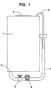
Figure 1 - View in lateral cut of "Hydromotive Box".
Figure 2 - View in perspective of "Hydromotive Box".
Figure 3 - View in lateral cut of "Hydromotive Box" with emphasis in the
relationship between the level of water in the reservoir of return (7) and the
superior
part of the main reservoir (1) of the hydromotive box.
Figure 4 - View in lateral cut only of the main reservoir (1) of "Hydromotive
Box", linked to a source of water, without need of the reservoir of return
(7).
CA 02732911 2011-02-03
2/13
Figure 5 - View in lateral cut with a main reservoir (1) that contains inside
of it
an flotation device (8) to increase pressure in the liquid included there
(main reservoir
-1).
Figure 6: Schematic view of the "Hydromotive Box", with flotation device (9)
inside the main reservoir (1).
Figure 7: Schematic view of the "Hydromotive Box" with closed main reservoir
(1) and flotation device (9) inside there and open reservoir of return (7).
Figure 8: Schematic view of the "Hydromotive Box" with main reservoir (1) and
flotation device (9) inside there and reservoir of return (7) both open
Figure 9: Schematic view of the "Hydromotive Box" with open main reservoir
(1) and flotation device (9) inside there and closed reservoir of return (7)
(under
negative pressure).
Figure 10: Schematic view of the "Hydromotive Box" with main reservoir (1)
and flotation device (9) inside there and reservoir of return (7) both open,
with
optional turbine.
Figure 11: Schematic view of the Hydromotive Box" with main reservoir (1)
and flotation device (9) inside there and reservoir of return (7) both closed,
with
optional turbine.
Figure 12: schematic view of the Hydromotive Box" with open main reservoir
(1) with flotation device (9) inside there and closed reservoir of return (7)
(negative
pressure), with optional turbine.
The original project of "HYDROMOTIVE BOX" that was filed in Brazil (INPI)
with application number BR-PI-0803305-6 of the present invention is described
as a
main reservoir (1), in cubic, cylindrical, or in any polyhedral shape, done in
metallic
structure or any other non deformable material, tightly closed and totally
sealed when
closed, with opening with cover (2) for provisioning, totally sealed when
closed,
having other opening linked to a empty tube (3), in curve of 1800 for entrance
of
water, touching its inferior part and perfectly welded to the main reservoir
(1), or
linked to this by process that allows total sealing, impeding the entrance of
air,
extending until the interior of the reservoir of return (7) of water; and an
opening
linked to a tube of water exit (4), in its inferior part, with register (5),
leading a turbine
or BWT (bomb working as turbine) (6), linked to the reservoir of return (7) of
water,
CA 02732911 2011-02-03
3113
smaller than the main reservoir (1), with the superior border open, whose
water level
cannot be below 8 meters of the superior part of the main reservoir (1), and a
piping
inside this deposit immersed in water and linked to the entrance of water (3).
The "HYDROMOTIVE BOX" operation is based on beginnings of the physics
and mechanic of fluids and it assists to the concepts and operations described
in the
sequence.
The main reservoir (1) of the hydromotive box should be produced in metal
totally sealed, besides the cover, when closed (2).
With the register (5) closed, it becomes full the main reservoir (1) and the
reservoir of return (7) of water, whose level of the water cannot be below 8
meters of
the superior part of the main reservoir (1) to make possible the action of the
atmospheric pressure. Once the reservoirs full, the register (5) is open to
allow the
passage of the water.
The water of the main reservoir (1), pressed by its weight, will drain by the
exit
piping (4), which will produce vacuum in the superior part of the main
reservoir (1).
Still when leaving the main reservoir (1), the water will pass by the turbine
(6),
moving it, and it will drain to the reservoir of return (7) of water,
increasing the level of
said reservoir of return (7).
The vacuum produced by the exit of water of the main reservoir (1) will be
filled out, making possible the suction of the water contained in the
reservoir of return
(7), in function of the atmospheric pressure, through the piping (3) that
links the main
reservoir (1) to the reservoir of return (7), keeping it balanced.
It is formed then a circular movement of fall and ascension of water, which
will
make possible the circular feed of the main reservoir (1), the circulation of
water by
the turbine (6), provoking its movement, the entrance in the reservoir of
return (7)
and the return by suction to the reservoir. To interrupt the process, it is
enough to
close the register (5). With the time, due to losses by evaporation, the level
of water
should be restored.
A variation of the "HYDROMOTIVE BOX" can be used for generation of
energy in small climbs and in places where there is water abundantly. For
such, it is
just used the main reservoir (1), the up to 8 meters above the level of water,
and a
piping for suction of water.
CA 02732911 2011-02-03
4/13
After many practical experiences, it was detected a few pressure in the main
reservoir (1) that made a deficient operation in the model, because the
atmospheric
pressure.
The inventor, after many studies in physics, hydraulics (hydrostatics/
hydrodynamics) and mechanical fluids still glimpsing an operational
improvement in
the hydromotive box above mentioned, has created a flotation device that
insides the
main reservoir is able to create an additional pressure in the liquid increase
there
(main reservoir), and consequently in the exit pipe and to optimize the flow
of
circulation of the water.
This device was addicted in the application number BR-Cl-0803305-6 filed in
Brazil (INPI).
Of an illustrative way, a cylindrical reservoir with 100 m of height and basal
diameter of 10 m, filled out with water, it presents in its base a pressure of
100 m of
column of water, 10 atm or 103.300 Kg / m2.
Passing the reservoir for a cylindrical shape, of same height, having in its
superior portion an enlargement in half-sphere shape, with diameter of 50 m
just like
a cup, in spite of supporting larger volume of water, therefore more weight,
due to the
hydrostatic paradox, the pressure in its base will continue to be of a column
of water
of 100 m. Using the same structure in cup shape, supposing that in its
superior part it
was removed part of the volume of water, equivalent to a half-sphere of
diameter of
40 m, in spite of the weight to decrease, the height is the same and, due to
the
fundamental theorem of the hydrostatic, the pressure in its base continues to
be of a
column of water of 100 m. Finally, if a half-sphere is put in an empty space,
in any
material, with enough density to float with its superior part, touching the
level of
water, by the Pascal beginning that the liquids transmit the pressure for
equal in all
the senses, said half-sphere passes its weight to the liquid that will be
distributed by
the area, being in this case the pressure in the bottom of the reservoir the
resulting
from the pressure of the column of 100 m of water added of the weight of the
half-
sphere divided by the internal area of the structure (bottom and laterals)
that contains
the water that supports said structure.
Mathematically, for the reservoir in cup shape with spherical superior part
and
cylindrical base with height of 100 m, diameter of the superior part of 50 m,
diameter
CA 02732911 2011-02-03
5113
of the base of 10 m, diameter of the sphere of 40 m and density of the sphere
of
0,99, it is obtained:
- Volume of the half-sphere = 16755,2 m3
- Weigh of the half-sphere = 16587,65 t
- Area of the interior of the structure = area of the half-sphere + area of
the lateral of
the cylinder + area of the base of the cylinder = 6361,74 m2
Being like this, the weight of the half-sphere when floating divided by the
total
internal area of the structure determines its pressure by m2 transmitted to
the water
that is equal to 2,61t.
The pressure above is transmitted to the whole liquid of the reservoir, being
the pressure in the base the result of the pressure exercised by the column of
water
added the pressure exercised by the half-sphere resulting in 105,91 t / m2.
In that way, pressure can be added to the water to win the resistance of the
atmospheric pressure, optimizing the operation of the hydromotive box by for
action
of the flotation device.
Obviously, the dimensions and shape of the reservoir, with smaller internal
area and the shape of the main reservoir with larger volume, possible since
compatible, will be calculated to overcome the pressure of the reservoir of
return (7),
added of the atmospheric pressure, obtaining like this the movement and/or
circular
flow of the water.
In order to better elucidate the present addition, it is made reference to the
enclosed drawing (Figure 5) that shows a lateral cut as a way of making
possible the
hydromotive box in half-spherical shape, whose shape reduces the attrition
provoked
by the curves, observer to the flotation device (8) included at the main
reservoir (1).
The improved "HYDROMOTIVE BOX" refers to a flotation device (8) added to
the water layer of the main reservoir (1), it could be in any shape, whose
medium
density is inferior to the one of the water, what makes possible its
flotation, calculated
in way to present the largest volume in a smaller area with the objective of
adding
pressure to the interior of the main reservoir (1). On the other hand, a valve
(9), of
only sense, was inserted ascendancy in the return piping (3) to allow better
primer of
the system. Basically, the device (8) should has conditions of balance,
flotation and
stability, capable of keeping it in the wanted position in the main reservoir
(1) and
CA 02732911 2011-02-03
6/13
allowing the circulation of the water in the system, in accordance with its
configuration and weight dimensioned to overcome the pressure of the water in
the
reservoir of return (7), added of the atmospheric pressure, optimizing the
performance of the hydromotive box.
Another improvement was filed in Brazil (INPI) with application number
BR-C2-0803305-6 made in the system proposes ways to increase the options for
operation of the "HYDROMOTIVE BOX" by alteration of the space disposition of
the
reservoirs with the purpose of obtaining larger versatility and income, that,
as it will
be demonstrated, is susceptible to work without the atmospheric pressure and
in an
ideal combination with the atmospheric pressure only acting in the main
reservoir (1),
as well as under vacuum or under atmospheric pressure in the main reservoirs
(1)
and reservoir of return (7).
In order to better understand this addition it is necessary to know about the
behavior of a same liquid in communicating vases:
- communicating vases with liquid of same density, the surfaces free from the
liquids
are in a same horizontal plan.
- communicating vases with liquids of different densities, when the balance
settles
down, a quota unevenness is generated inversely proportional to the densities
of the
liquids.
Therefore, in a liquid in balance, the pressures should be the same ones to
count of the same horizontal plan.
The "HYDROMOTIVE BOX" has the main reservoir (1) and the reservoir of
return (7) united, in their inferior part, by an exit piping, characterizing a
communicating vase with the same liquid (water). Theoretically, the liquid is
balanced
equaling its pressure in a same horizontal point; however, the flotation
device
included in the main reservoir (1) increases the internal pressure of said
reservoir.
Therefore to equal the pressure in two points horizontally aligned, one in the
line of
the reservoir of return (7) and other in the line of the main reservoir (1),
and to obtain
balance, the column of water of the reservoir of return (7) will be elevated
until reach
pressure equivalent to the internal pressure of the main reservoir (1).
Consequently,
the liquid is balanced equaling its pressure in a same horizontal plan,
however the
CA 02732911 2011-02-03
7/13
flotation device, included in the main reservoir (1), increases the internal
pressure of
the said reservoir.
Until then it was used the premise that the atmospheric pressure acting in the
reservoir of return (7) elevates the column of water for the return piping.
This is valid,
but, according to the explained concept, it is enough the pressure exercised
by the
flotation device to elevate the column of water in the reservoir of return
(7).
Such statement can be mathematically proven for the main reservoir (1) in
semi-spherical shape with diameter of 100 m and height (stripe) of 50m. The
flotation
device has semi-sphere shape with diameter of 80 m and stripe or height of 40
m
with density of 0,99 in relation to water (1t / m). The exit piping is
cylindrical with
diameter of 10m and extension of 50m. Finally, the reservoir of return (7) is
cylindrical with diameter of 10m.
By the fundamental theorem of the hydrostatic, the difference of pressures,
between two points any of a same liquid in balance are same to the weight of
the
liquid column that has as base the surface unit and as height the vertical
distance
between two points (A and A').
Therefore the pressure will be calculated in the point A', superior point,
aligned
to A and that it receives the pressure of the column of water of the main
reservoir.
Take a point A, located to 10mt above the bottom of the main reservoir; the
pressure in A will be the height of the column of water in meters added of the
pressure of the flotation device that acts in the internal area of the main
reservoir (1)
added to the internal area of the exit piping.
Being like this:
- Column of water on A - 40 m.c.a. or 4 atm (10.330 kgf/m2), or 41.320 kgf/m2;
Weigh of the flotation device
D = MN or 0,99t/m3 = M / 4 x? x 401/ 6 or M = 132.701,18t
Internal area of the main reservoir:
4?r2/2 or4x?x50x50/2=15.708m2
Internal area of the exit piping (4)
Area of the cylinder or rrr2 + 2nr x length or (n x 5 x 5) + (2 u x 5 x 50) =
1.649,34m2
Total of the area it internals made calculations
15.708m2 + 1.649,34m2 = 17.357,34m2
CA 02732911 2011-02-03
8/13
The pressure exercised by the flotation device will be its weight divided by
the
calculated area:
Pressure = 132.701,18t / 17.357,34m2 = 7,64t/m2 or 7.640 kgf/m2
The pressure in the point A is of 41.320 kgf/m2 for the height of the column
of
water and it will be added by the pressure exercised by the flotation device,
7.640
kgf/m2, the total pressure in the point A will be 48.960 kgf/m2.
However, so that this system is balanced it should have the same pressure in
the two vases, then the height of water in the reservoir of return (7) should
be larger
than the height of the water of the main reservoir, because it has in its
interior the
flotation device. This condition will be analyzed in the next 4 cases:
- Case 1: the main reservoir (1) is closed to vacuum and the reservoir of
return (7)
under atmospheric pressure.
The column should be elevated 48,96 m above the point A', but the
atmospheric pressure of 10.330 kgf/m2 acts reducing its height and stabilizing
it in
38,63m, in this case the total height of the level of water of the reservoir
of return (7)
will be of 48,63m (1,37m below the level of water of the main reservoir) once
the
point A is 10m above the inferior level of the water, this height of the
column is
enough to keep the "Hydromotive Box" operation, because the atmospheric
pressure
will elevate the water by the return piping, making it to return to the main
reservoir (!).
- Case 2: the main reservoir (1) is under atmospheric pressure just like the
reservoir
of return (7).
The internal pressure of the column of water and of the flotation device added
of the atmospheric pressure will result in a pressure of 59.290 kgf/m2 above
the point
A and the column of water in the reservoir of return (7) will be of 48,96m
above the
point A', passing in 8,96m the height of the main reservoir (1), it will be
added of the
atmospheric pressure, resulting in a total pressure equal to 59.290 kgf/m2.
- Case 3: both reservoirs are closed to vacuum.
The pressure in the main reservoir (1) above the point A will be of
48.960kgf/m2 and in the reservoir of return (7), to keep the balance it will
be same, or
48,96 m, also passing in 8,96m the height of the main reservoir (1), as in the
previous case.
CA 02732911 2011-02-03
9/13
- Case 4: the main reservoir (1) is under atmospheric pressure and the
reservoir of
return (7) is closed to vacuum.
The internal pressure of the column of water and of the flotation device added
of the atmospheric pressure will result in a pressure of 59.290 kgf/m2, to
keep the
balance the column of water in the reservoir of return (7) will be of 59,29m
above the
point A', passing in 19,29m the height of the main reservoir (1).
In order to better elucidate the present addition, it is made reference to the
enclosed drawings (Figures 6 to 12).
The "HYDROMOTIVE BOX" of this improvement refers to a hydromotive box
(C) composed of a main reservoir (1) of semi-spherical shape, united by piping
(4) of
exit to the reservoir of return (7). The flotation device (9), equally semi-
hysterical,
increases the internal pressure in the main reservoir (1), and to equal the
pressure in
the points (A and A') with the same quotas (h and h'), and to obtain the
balance of
the liquid, the column of water in the reservoir of return (7) will rise (H')
until reaching
the pressure equivalent to the internal pressure of the main reservoir (1) of
level (H),
as demonstrated in the figure 6.
The figure 7 demonstrates the operation of the hydromotive box (C) with the
main reservoir (1) closed with cover (2) to vacuum and the reservoir of return
(7)
under atmospheric pressure (PA).
The figure 8 demonstrates the operation of the hydromotive box (C) with the
main reservoir (1) subject to the atmospheric pressure (PA) just like the
reservoir of
return (7).
The figure 9 demonstrates the operation of the hydromotive box (C) with the
main reservoir (1) open, as well as the reservoir of return (7) to vacuum.
The figure 10 shows the hydromotive box (C) worked under atmospheric
pressure in the reservoirs (1 and 7) with option of putting a turbine (6) in
the return
piping (3) subsequent to the register (5).
The figure 11 shows the hydromotive box (C) worked with the reservoirs (1
and 7) with option of putting a turbine (6) in the return piping (3)
subsequent to the
register (5).
The figure 12 shows the hydromotive box (C) worked with the main reservoir
(1) open and the reservoir of return (7) closed to vacuum with cover (2), with
option
CA 02732911 2011-02-03
10/13
of putting a turbine (6) in the return piping (3) subsequent to the register
(5), in that
case the exit of water should be under positive pressure.