Note: Descriptions are shown in the official language in which they were submitted.
CA 02732917 2015-03-11
WO 2009/117161 PCT/1352009/001800
EXTERNAL SYSTEM FOR ROBOTIC ACCURACY ENHANCEMENT
Fmr D OF THE INVENTION
[00002] The present invention relates to
systems for robotic and
equipment accuracy enhancement and methods.
BACKGROUND OF THE INVENTION
[00003) In the field of robotics and
Numerically Controlled (NC)
motion systems, a great amount of effort and research has been dedicated to
modeling
and characterizing said motion devices and motion systems in pursuit of
accuracy
enhancement, With industrial robots in particular, manufacturers and after-
market
companies have focused mainly on modeling the 'as-built' conditions of a robot
Usually, parameters in the kinematic model of the robot are adjusted based on
the
results of a one-time volumetric calibration of the robot in a variety of
poses
throughout its work envelope; typically, an external metrology device such as
a laser
tracker is employed to measure and compare the actual versus commanded pose
(or
simply position) of the robot over a distribution of locations. A further
expansion of
the aforementioned volumetric calibration of a robot includes similar methods
that
can be periodically performed on the manufacturing floor, but are not intended
to be
carried out during production. Such off-line calibration methods only provide
a snap-
shot in time of the robot's characteristics, and do not account for the
degradation in
1
AAAAAA 11.111111TIAU mow. n .114 i4
CA 02732917 2010-09-21
WO 2009/117161 PCT/US2009/001800
accuracy due to wear or possible thermal changes that inevitably occur in
between
system calibrations.
[00004] The art is replete
with various prior art laser tracking systems
methods, which can locate a target in any of three to six degrees of freedom
(DOF),
thereby aligning robotic devices relative to the target to perform operations
on a
workpiece. These prior art systems and methods are taught by United States
Patent
Nos. 4,412,121 to Kremers et al., 4,707,129 to Hashimoto et al., 4,714,339 to
Lau et
al., 4,792,228 to Haffner, 5,042,709 to Cina et al., 5,100,229 to Lundberg et
al.,
5,907,229 to Snell, and 6,400,452 to Maynard. The
United States Patent No.
4,714,339 to Lau et al., for example, teaches a three dimensional tracking
system is a
simplification of the five degree of freedom tracking system.
[00005] Still other accuracy
enhancement methods involve in-line
updating of the robot's kinematic model parameters, usually either via
periodically
presenting the robot end effector (in various poses) to fixed sensors that
typically do
not exist within the actual 'work volume' of the robot or via providing
'enhanced'
encoder read-outs for the robot joints (or combination thereof). At least one
from this
class of methods does involve measuring the robot end effector position in the
'work
volume' of the robot, but does not accomplish this during the robot's actual
work
cycle. All the aforementioned methods, whether intended to be 'one-shot' or
periodically updated, are ultimately only predictive, and can be considered
'passive'
with respect to truly knowing the current pose of the end effector.
[00006] Active (real-time)
measurement of a robot's end effector via
external metrology devices has long been investigated, and many commercial
applications are currently being undertaken or have already been implemented.
Laser
trackers and laser radar units certainly possess the requisite accuracies to
sufficiently
2
CA 02732917 2010-09-21
WO 2009/117161
PCT/US2009/001800
guide/correct a robot for a variety of manufacturing processes, but are single
line of
sight (LOS) devices. In the case of laser trackers, they require time to
'search' for
their corner cube targets. For laser radar, hemispherical targets are
typically scanned.
Each type of system is prohibitively expensive and slow for widespread
application in
real-time active robotic correction. 6-DOF generation using traditional corner
cube
reflectors requires either multiple laser trackers or, more commonly,
measuring
multiple corner cube targets on a robot's end of arm tool (EOAT). Many
specialized
target designs have been described that are meant to determine 5-DOF or 6-DOF
of
said target by employing a single line of sight from a laser tracker (using
interferometric and/or time of flight techniques). Such a device employing a
corner
cube with an apical opening, smaller than the laser beam diameter, that allows
a part
of the beam to strike a photosensitive detector behind it, thereby providing 5-
DOF
(x,y,z,tilt,yaw) of the target is described in the United States Patent No.
6,667,798 to
Markendorf et al. United States Publication No. 20060222314 to Zumbrunn, et
al.,
for example, adds patterned photo-emitters to the 5-DOF target; when measured
by an
external camera incorporated onto the laser tracker, target roll can also be
determined.
Commercially, the active probe possesses multiple LEDs that are picked up by
the
camera piggy-backed on the laser tracker. In this case, the laser tracker does
not
waste time searching for the corner cube since it uses a priori information of
the
probe's location via the camera's measurement of the LEDs. There are several
limitations for solutions of this sort. Since the apex angles between the LEDs
are
quite small as viewed by the camera, any error in determining the transverse
position
of the LEDs contributes to angular errors in the 6-DOF solution. Similar
angular
ambiguity results from the distance between the photosensitive device and the
corner
cube being so small; any error in calculating the position of the laser spot
on the
3
CA 02732917 2010-09-21
WO 2009/117161 PCT/US2009/001800
photosensitive surface results in a large angular error of the target itself
owing to the
need for keeping the target's dimensions small enough to fit on a robot end
effector.
Additionally, this grey-scale option is quite expensive, and the probe is too
large and
directionally-limited to be mounted on many robotic end effectors, especially
where
the process requires that the robot exercises a full range of poses. United
States
Publication No. 20030043362 to Lau et al. describes an active target probe
used in
conjunction with a laser tracker that provides 6-DOF of the target, wherein
polarized
light is used to deduce roll of the target. This target also has the advantage
of rotating
to keep its aperture perpendicular to the incident laser tracker beam. Still,
this target
has angular limitations for yaw, pitch, and roll detection; lacks the
requisite accuracy
for higher-precision robot correction applications; is still too large to
incorporate into
many end-effector designs; and is expensive. The probes described here are
generally
too large to be positioned close to the tool center point (TCP) of the robot,
resulting in
'lever-arm' effects when ascertaining the pose of the TCP. And, coupled with
the fact
that they require a laser tracker or camera-enhanced laser tracker to perform,
such
systems are prohibitively expensive, especially when compared to the base
price of a
standard articulated arm robot.
[00007] Indoor optical GPS
has recently made inroads to many
manufacturing solutions and can provide the current pose of a robot, but such
systems
cannot at this time demonstrate accuracies near those that are needed for high
precision robot guidance applications. The systems do have receivers with
large
fields of view over which to pick up the laser output of the transmitters, but
are still
LOS devices. In the context of high precision robot guidance, the cost-
effectiveness
of indoor GPS can only be realized when large numbers of receivers are
required on
the manufacturing floor.
4
CA 02732917 2010-09-21
WO 2009/117161 PCT/US2009/001800
[00008] Photogrammetry has
been employed for active robotic
correction to varying degrees of success. Most use end effector-mounted
'active'
targets, such as LEDs, and do not depend on more traditional techniques using
external lighting of reflective stickers. These photogrammetric solutions
generally
fall into two categories. The first involves 'single sensor housing'
solutions, where
multiple photosensitive devices are distributed within a single housing
(typically there
are three distinct LOS emanating from the housing). The second involves using
multiple, statically-positioned cameras whose fields of view provide overlap
within
the volume of interest. Photogrammetric solutions have the great advantage of
very
high refresh rates (for example, three targets can typically be measured in
less than a
millisecond, thus providing 6-DOF of an object). This speed allows for dynamic
tracking of multiple coordinate frames, and can even tolerate most production
environment vibrations. Considering these features, one would logically
conclude
that this class of solutions holds the most promise for high precision active
robotic
correction. There are a few subtleties that bear explanation, however. First
off, the
volume of interest of 'single sensor housing' photogrammetric solutions is
limited to a
wedge that typically extends only to 6 meters from the device (the closer you
get to
the sensor, the smaller the transverse field of view becomes). Since the
allowable
spacing between the LED targets that need to be placed on a typical robot end
effector
is usually small, poor apex angles generally result between the LEDs as viewed
by the
system. In an effort to put all the photosensitive devices and optics in a
single sensor
housing, the apex angles between each line of sight are likewise compromised.
Thus,
while these types of sensors are typically quite accurate in the transverse
directions,
distance determination is the weakest component of the 6-DOF transform. The
poor
apex angles could be corrected by adding another photogrammetric head in the
work
CA 02732917 2010-09-21
WO 2009/117161 PCT/US2009/001800
cell at nearly 90 degrees to the first photogrammetric head, but the resulting
overlap
between the two wedge volumes becomes prohibitively small for most
applications.
Taking into consideration that a single head photogrammetric system typically
costs
as much as a laser tracker, the cost per measurement volume becomes a huge
factor.
The second approach to active target photogrammetry generally uses multiple
sensors
with overlapping fields of view, achieving significantly better apex angles
among the
cameras. During operation, the sensors are statically positioned, and the
cameras
must be aggressively internally calibrated over their entire volumes of
interest.
Again, though, the volume of overlap between the cameras is limited. And,
while the
sensors for these types of photogrammetric systems are cheaper than the
'single
sensor housing' varieties, they are still considerable when compared to the
cost of a
robot, so adding additional LOS capability by adding more sensors is seldom a
viable
option.
[00009] Still another class
of devices that could be used for determining
the pose of a robot BOAT includes theodolites and total stations. There are
now total
station models that are automated, allowing the electronic theodolite to be
aimed/driven remotely via a computer. These devices also include time of
flight
ranging devices that employ reflective targets (allowing for line of sight
measurements up to a few kilometers) or no targets at all (lighter-colored
surfaces can
be measured at a few hundred meters' distance). Ranging accuracy is typically
on the
order of 2 ¨ 3 mm. Pointing accuracy (azimuth, elevation) range from 5 ¨ 8
arcseconds for construction grade systems all the way up to 0.5 arcseconds in
precision systems. As a stand-alone gimbal, such systems cannot provide
accuracies
greater than those already achieved by robots with enhanced accuracy modeling.
Even if the ranging capability was not used in favor of locating the angular
positions
6
CA 02732917 2010-09-21
WO 2009/117161 PCT/US2009/001800
of 3+ reflectors on a robot EOAT and solving 6-DOF via traditional
photogrammetric
techniques, one again arrives at a poor apex-angle solution. Multiple gimbals
would
allow for photogrammetric determination of an EOAT's 6-DOF pose by allowing
for
more optimum apex angles, and the novel invention described herein seeks to do
so
by employing an even less-expensive alternative by obviating any range-
detection
hardware.
[000101 The inherent
limitations of 'passive' robot correction, along
with the performance shortcomings and cost barriers of existing 'active' robot
correction systems, were all taken in to consideration when developing the
following
affordable, external active robot correction system. Additional techniques
include
multiple length measurement with laser, acoustics, or wires; and multiple
camera-like
systems. Stereo-triangulation is undesirable since it requires a minimum of
two
tracking systems and it is a static measuring technique. Similarly, imaging by
camera
is undesirable since the resolution of the system is typically much too low to
adequately cover the working envelope of a robot, in addition to the
unrealistic
stabilities and accuracies required when generating/maintaining the internal
calibrations of such optical systems.
[00011] Therefore, there is
a long-standing need for an improved
system and method of external robotic accuracy enhancement.
SUMMARY OF THE INVENTION
[00012] A system for robotic
accuracy enhancement (the system)
includes a plurality of robotic devices adaptable for multi-axial movement.
Each
robotic device includes an arm having an end of arm tool (EOAT) presenting at
least
one axis for performing at least one operation on a workpiece. A plurality of
multi-
axial devices projects laser beams oriented relative to said robotic device. A
plurality
7
CA 02732917 2010-09-21
WO 2009/117161
PCT/US2009/001800
of removable target elements is connected to the BOAT of each robotic device.
Each
target element is pre-certified in the BOAT coordinate frame, allowing the
robotic
devices to orient the EOAT relative to the workpiece before performing an
operation
on the workpiece as each of the target elements are illuminated by the multi-
axial
devices. Each target element comprises a base, such as a plate, formed from at
least
one of metallic and non-metallic materials and presents a plurality of
openings
defined therein. The base presents a plurality of removable nest elements
attachable
to the respective openings defined in the plate and a plurality of calibration
targets
magnetically supported by the respective nest elements. The base further
includes a
photosensitive array defined in the plate. A housing encapsulates each of the
target
elements, said housing having a shutter device. A
controller is operably
communicated with the target elements, the plurality of multi-axial devices,
and the
plurality of robotic devices for manipulating at least one multi-axial device
to activate
at least one target element.
[00013] The
system actively determines the 6-DOF pose of the robotic
device. An inventive concept of the system includes using multi-axial devices
for
projecting lasers (laser pointing devices, also referred to here as beacons),
onto
BOAT-mounted targets (the active targets) to actively determine the pose of
the
BOAT at distinct work positions of at least one motion device without the use
of any
range detection hardware. The beacons are small, inexpensive, and inherently
modular, and thus can be distributed throughout a work cell to guarantee
multiple
LOS. The beacon quantities and positions as set forth in the present
application are
not intended to limit the scope of the present invention and are optimized to
the CAD
design of the work cell and simulated paths of at least one motion device. The
beacons may operate on more than one motion device, thus reducing the per
motion
8
CA 02732917 2010-09-21
WO 2009/117161
PCT/US2009/001800
device cost of the system in work cells utilizing multiple motion devices.
Multiple
LOS ensure good apex angles for more accurate determination of the EOAT pose,
unlike many photogrammetric metrology devices. The active targets contain at
least
one inexpensive, photosensitive device such as, but not limited to, CMOS or
CCD
arrays and/or line arrays. Being that these devices have an active surface
area, there
usually will not be the need to 'search' for the active targets, unlike a
laser tracker.
Once the initial certification of the proposed system within the work cell is
complete,
faulty beacons or active targets can be swapped out without loss of
certification
information.
[00014] One of the advantages of the present invention is to provide
the
system that obviates the need to purchase expensive modeling/correction
packages
that are commonly sold with industrial robots.
[00015] Another advantage of the present invention is to provide the
system at a low price, which is significantly cheaper on a per robot basis
than prior art
systems.
[00016] Still another advantage of the present invention is to
provide
the system that serves as a process monitoring tool, since the EOAT pose of
the
motion device is actually measured at each work position, instead of simply
being
estimated/predicted as per many existing 'passive' robot accuracy enhancement
packages. Such a system can be used to archive pose data during a process for
later
analysis.
[00017] Still another advantage of the present invention is to
provide
the system that significantly reduces or eliminates the need to perform in-
situ
calibrations or characterizations of motion platforms in an effort to 'model'
or
'characterize' the motion device. Since this is an active measurement system,
the
9
CA 02732917 2010-09-21
WO 2009/117161
PCT/US2009/001800
proposed system may result in cheaper motion platforms being able to achieve
tighter
pose tolerances. An example would be the ability to replace expensive NC
machines
with cheaper industrial robots.
[00018] Since
the proposed system has the capability to monitor the
pose of the EOAT in real time, an avenue for tracking/correcting the pose of
the
EOAT while it performs its work (such as drilling) is made possible. Since the
actual
pose of the EOAT is measured, backlash can be overcome when the motion
device's
pose is corrected since the motion device may not be allowed to commence work
until
an 'acceptable' pose is achieved.
[00019] Still
another advantage of the present invention is to provide
the system that takes a 'black-box' approach to robot accuracy enhancement, in
effect
measuring the aggregate result of all the contributing factors to robot pose
error
without regard to implicitly measuring or modeling any individual contributor.
For
example, temperature effects, both ambient and internal to the motion device
(such as
servo temperature), are automatically accounted for via the system. Deflection
is also
accounted for via the system (think of the extra modeling necessary when a
robot is
mounted to additional slide units). Even non-geometric effects that are not
usually
included in a robot's kinematic modeling such as joint flexibility, link
flexibility, and
gear transmission error are actively accounted for in such a system. Robot or
end
effector wear can also be tracked over thousands of duty cycles utilizing such
a
system.
[00020] Still
another advantage of the present invention is the ability to
link together or update various coordinate frames by placing the active
targets on the
workpiece, fixed about the work cell, on a movable device such as a tripod, or
on
palletized systems. This ability allows for a multitude of capabilities, such
as
CA 02732917 2010-09-21
WO 2009/117161 PCT/US2009/001800
generating part-to-world transforms, compensating for temperature drift within
a work
cell, initially calibrating beacon-to-world poses, subsequently recalibrating
beacon-to-
world poses, or establishing the relationship between a fixed work cell and a
palletized robotic system that moves to it, or even monitoring of automated
guided
vehicle (AGV) systems.
BRIEF DESCRIPTION OF THE DRAWINGS
[00021] Figure 1 illustrates
a front view of a multi-axial device for
steering a light beam;
[00022] Figure 2 illustrates
a side view of the multi-axial device of
Figure 1;
[00023] Figure 3 illustrates
a perspective and exploded view of an
active target device of the present invention;
[00024] Figure 4 illustrates
the active target of Figure 4 enclosed by a
housing;
[00025] Figure 5 illustrates
a perspective view of an end of arm tool of
a robotic device having a plurality of active targets connected thereto;
[00026] Figure 6 illustrates
an environmental view of an external
system for robotic accuracy enhancement of the present invention;
[00027] Figure 7 illustrates
a schematic view of work components of
the external system for robotic accuracy enhancement in a typical
manufacturing
environment;
[00028] Figure 8 illustrates
a perspective view of a device for
calibrating the active target of the present invention;
[00029] Figure 9 illustrates
a partial and side view of the device for
calibrating the active target of Figure 8;
11
CA 02732917 2016-12-01
WO 20401117141 PCT/US2.09/001909
1000341 Figure 10 illustrate*
another perspective view of an end of arm
tool of a robotic device having a plurality of active targets connected
thereto and
activated by laser beams;
1000351 Other advantages of the
present invention will be readily
appreciated u the same becomes better understood by reference to the following
detailed description when considered in connection with the accompanying
drawings
as shown tbrtber below.
DETAILED DESCRIPTION OF THE PREFERRED EMBODIMENT
(000361 Referring to the Figures
wherein numerals indicate like or
corresponding puts, an inventive system and method for robotic and equipment
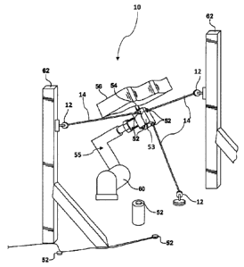
accuracy enhancement is generally shown at 10 in Figure 6. The system 10
includes a
plurality of multi-axial devices, generally shown at 12 in Figures 1 and 2.
These
multi-axial devices 12, i.e. beacons, are capable of steering a light beam 14,
such as a
Laser, LED, or incoherent source without limiting the scope of the present
invention.
TYPically, the multi-axial device would be a gimbal at shown in Figure 1,
which
illustrates a front view of the multi-axial device 12 and Figure 2, which
illustrates a
side view of the multi-axial device 12. Those skilled in the art will
appreciate that
12
CA 02732917 2010-09-21
WO 2009/117161
PCT/US2009/001800
other devices for generating and steering light beams may be used with the
present
invention without limiting the scope of the present invention. The beacon 12
presents
a certain mechanical pointing resolution (the ability to physically point the
beam to a
commanded position) along with a mechanical pointing determination (the
ability to
determine the vector of the laser beam 14 possibly via calibrated encoders for
the
azimuth and elevation angles). The beacon 12 would steer a laser source (solid
state
diode, fiber-coupled, or other) contained in a housing 20, producing a
collimated or
semi-collimated output beam 14. It is also quite possible that the laser
output could
be in a pattern other than that of a traditional beam, such as a line or
crosshairs. If the
laser exit aperture 22 defined in the housing 20 is not perfectly coincident
with the
intersection of the azimuthal axis 26 and the elevational axes 24, then the
beacon 12
would need to be modeled/calibrated to determine the (x,y,z) position of the
laser exit
aperture at any given pointing direction. The beacon 12 could be attached to a
mounting base 28 of the beacon 12 and so be easily incorporated into a
manufacturing
environment. Services, such as power and communication cables or air lines 30,
would run from the work cell controller out to each beacon 12. In this
example,
Figure 2 shows that the laser exit aperture 22 is nearly coincident with the
center of
rotation of the gimbal (center-mounted in the housing).
[00037] The
system 10 proposed herein would have software that would
control a plurality of the beacons 12. Again, the beacon manufacturer may
retain
access and control of the beacon's internal calibration/modeling. However, the
software described in the present application would need to be able to point
the
beacon 12 (possibly with real-time feedback), turn the laser on/off, and
receive the
laser beam's 14 (i,j,k) vector (or elevation, azimuth angles) in its native
coordinate
frame along with possibly the (x,y,z) of the laser exit aperture 22, again in
the
13
CA 02732917 2010-09-21
WO 2009/117161
PCT/US2009/001800
beacon's 12 native coordinate frame (see above). The proposed metrology system
10
will employ novel target elements, i.e. active targets generally shown at 16
in Figures
3 and 4.
[00038] As shown
in Figure 3, the target element 16 includes a base
defined by a plate 44 defining three or more attachment points or openings 40.
The
base may include other configurations, and is not limited to the plate. The
plate 44
could be fabricated from metal or another machinable, preferably low CTE
material.
The attachment points 40 receive calibration targets 36 supported on
calibration target
nests 38. In this example, the attachment points 40 are dowel holes, and the
target
nests 38 are doweled, magnetic cups, the type that are typically used to hold
theodolite target spheres, spherically mounted passive photogranunetry
targets,
spherically mounted active photogrammetry targets, or spherically mounted
retroreflectors (SMRs) used with laser trackers. Mounted to the plate 44 is a
photosensitive array 34, which could be a CMOS array, CCD array, or line scan
sensor and the like. Services
42 for the array could include power and
communication cables.
[00039] Figure 4
shows the target element 16 enclosed or encapsulated
in a protective housing 46. This housing 46 may employ a shutter 48 that could
be
pneumatic or electric. Services 50 would run to the shutter 48, with the
option to use
an additional air line to periodically blow dust from the target element 16 or
to create
positive air pressure within the puck enclosure itself, thus acting as a dust
barrier. As
the target element 16 may be mounted to motion devices, i.e. a robotic device
or in
the work cell itself, they will probably include dowels or other features that
would
serve for generic/standardized mounting.
14
CA 02732917 2010-09-21
WO 2009/117161
PCT/US2009/001800
[00040] Figure 5 demonstrates the target elements, generally
indicated
at 16 being deployed on an end of arm tool, i.e. EOAT, generally indicated at
53 in
Figure 5, of the robotic device, generally indicated at 55 in Figure 6. As
will be
discussed later on, it is desirable to mount (and have LOS to) at least 3 of
the target
elements 16 at mutually orthogonal orientations onto the EOAT 53 and relative
to a
central axis 54 of the EOAT 53. During the work cell tooling certification
phase,
each target element 16 is defined in the tool coordinate frame (the EOAT
frame),
relative to the tool center point, i.e. the aforementioned central axis 54.
The central
axis 54 is defined as the origin of the tool frame. The target element
services would
be dressed along the robotic device 55 out to the EOAT 53.
[00041] Figure 6 demonstrates how the proposed system could be
deployed in a manufacturing environment. The encapsulated target elements 52
would be mounted to the EOAT 53, along with additional target elements 52
mounted
to the floor, station tooling, or, for example, carbon fiber or concrete posts
62. The
beacons 12 would also be distributed throughout the work cell. Their numbers
and
positions would most likely be optimized based on a computer simulation of the
robotic device 55 as it performs the intended process. Since the beacons 12
will
usually be able to guide the robotic device 55 quicker than the device 55 can
perform
its work, the system 10 allows most of the beacons 12 to perform duplicate
guidance
duty for other robotic devices 55 in the work cell, thus lowering overall
system
hardware cost. For instance, if it takes ten seconds for the robotic device 55
to drill a
hole in a workpiece 56, but only three seconds to guide that robotic device 55
to the
correct work position, these beacons 12 could spend the other seven seconds
guiding
other robotic devices 55 in the work cell. In this example, the tool TCP 54,
also
aligned with a drill tip, would be guided to the correct work pose, i.e.
location and
CA 02732917 2010-09-21
WO 2009/117161
PCT/US2009/001800
orientation, before being permitted to drill the workpiece 56. Alluding to the
above,
the target elements 16 may be affixed to control points on the workpiece 56.
In this
way, the part-to-world relationship may be determined for each part entering
the work
cell.
[00042] Figure 7 demonstrates the interconnectivity of the deployed
system 10 in a typical manufacturing environment. A computer will control
multiple
beacons and EOAT target elements, with possibly some additional target
elements
mounted to the workpiece 56, or distributed inside the work cell. The station
computer can communicate to one or more line/station PLC (Programmable Logic
Controller) and at least one robot controller. It may be possible that each
target
element could have an on-board computer chip to perform image processing, but
this
upgrade may not always be warranted if cost factors outweigh the need for
decreased
cycle time. It is intended, though not required, that the software running the
system
would be a 'slave' to the robotic device 55, measuring only when the robotic
device 55 so requests.
[00043] Figures 8 and 9 present a novel method of how newly-
manufactured target elements 16 are calibrated. The idea is to relate the
coordinate
system of the photosensitive array (pixel space) to the positions of the
removable,
nested 38 metrology targets 36 in a 'target coordinate system', and save the
results in
a calibration file linked to the unique ID of the target elements 16. The
target
coordinate system will be derived from a calibration stand shown at 61 in
Figures 8
and 9. Additional standardized mounting features may be included to the target
elements 16 (such as three dowels protruding from the back of the plate 44)
and
defined in the 'target coordinate system' at this point in time also. To
ensure
16
CA 02732917 2010-09-21
WO 2009/117161
PCT/US2009/001800
dimensional integrity, the calibration stand 61 may reside in a climate
controlled
enclosure (not shown). The calibration process is described in Figure 10.
[00044] All
the following part numbers refer to those in Figures 8 and
9. An
external metrology system, such as theodolites, laser tracker, or a
photogrammetric system, is set up about the calibration stand 61. The
metrology
targets 36, appropriate to the external metrology system, are positioned into
the
doweled target nests 38, which subsequently would be placed in (for example)
dowel
holes 40 on the calibration stand 41. The first time the calibration stand 61
is
certified, the (x,y,z) coordinates of each target location of the calibration
stand 61 is
recorded in the 'target coordinate system'. By measuring at least three of
these target
positions, the metrology device can report in the calibration stand
coordinates.
1000451
Alluding to the above, the target element plate 72 is affixed to a
slide unit 70 and powered up via the service cables 42. The operator (not
shown)
installs at least three nested targets 36, 38 in the dowel holes 40 of the
target plate.
The operator positions a stop device 68 onto two posts affixed to the
calibration stand
61. The operator then gently moves the slide unit 70 forward along rails 66
until the
stop device 68 contacts the cover glass of the photosensitive array 34. At
this point,
the slide unit 70 is locked into place, and the operator removes the stop
device 68. It
may be desirable for the stop device 68 to contact the inactive area
surrounding the
photosensitive array 34, and all this would require is determining and
possibly
controlling the manufactured distance between this surface and the array's
surface.
Let the manufactured thickness of the array cover glass be D.
[00046] The
first time the calibration stand 61 is certified, the array
cover glass-contacting surface of the stop device 68 may be defined as being
at (for
example) 'target coordinate system' z = D. If the 'z' axis of target
coordinates runs
17
CA 02732917 2010-09-21
WO 2009/117161
PCT/US2009/001800
negative as one goes toward the active target, this would imply that the
photosensitive
array surface is at the z = 0 plane. The axes shown in Figure 8 present a
possible
target coordinate system orientation, with the origin maybe located somewhere
near
the center of the photosensitive array. Another aspect of the calibration
stand 61 is
the laser output apertures 64. These apertures 64 would produce laser beams
focused
to the approximate position of the photosensitive array, at z = 0. Here the
beams are
shown as circular in cross-section, though if the photosensitive element of
the target
elements 12 would happen to be a linear array or arrays, the laser output may
very
well be a set of one or more crossed lines.
[00047] During the initial certification of the calibration stand
61,
theodolites could easily be used to measure the (x,y) position each of the
focused laser
beams at the z = D (cover glass) plane. Thus, when one projects the focused
laser
beams 74 onto the array 34, each of the (for example) four laser spot centers
is
already known in target coordinate space. By processing the centers of at
least three
laser spots in pixel space, enough information is known to calculate the pixel
space-
to-calibration stand transformation matrix. Here, calibration stand
coordinates and
target coordinates are used synonymously. This entire active target
calibration
procedure could be obviated by precision machining the target element 16. In
this
case, the alignment and position of the photosensitive array relative to the
rest of the
target element 16 would have to be extremely accurate.
[00048] The obvious down side of this approach is a greatly
increased
target element 16 manufacturing cost. However, each target element 16 would
allegedly be identical to the others, so a single, CAD-determined pixel space-
to-target
coordinate transform could be used. In the case where every aspect of the
target
element 16 is precision machined except for the placement/alignment of the
18
CA 02732917 2010-09-21
WO 2009/117161
PCT/US2009/001800
photosensitive array, one could eliminate the need to have an external
metrology
device measure the positions of the nested targets. For manufacturers that
lacked an
external metrology device such as a laser tracker (4100,000.00), the added
cost of
purchasing or renting (¨$1000.00/day) such a metrology device may be larger
than
the extra cost of precision machining almost all dimensions of the target
element 16.
[00049] In summary, the laboratory calibration of the target
element 16
defines the relationship between pixel space of the photosensitive array and
the
positions of external metrology targets that can be temporarily affixed to the
active
target plate. Additional features on the target element 16, such as mounting
dowels,
may also be defined in the target coordinate space during calibration. Each
target
element 16 will most likely possess a unique ID, and the active target
calibration file
will be linked to this identifier. This process is mapped out in Figure 10.
[00050] During the work cell certification phase on the
manufacturing
floor, the calibration file allows for the pixel space of target element 16 to
be defined
relative to another coordinate frame (such as World, Part, or Tool). This is
achieved
by setting up an external metrology system in the desired coordinate frame,
and then
measuring at least 3 target positions on the target element 16. A best-fit of
3 or more
data pairs (active target coordinates from the calibration file, external
coordinate
frame coordinates from external metrology device) generates the active target-
to-
external coordinate frame matrix.
[00051] Figure 11 summarizes a novel method of how an active target
mounted to the robotic device 55 can be defined relative to said tool's
coordinate
frame. The target element 16 already possesses a pre-defined coordinate frame
via
the calibration process described in Figure 10. By employing an external
metrology
system reporting in the EOAT coordinate frame, appropriate targets can be
nested into
19
CA 02732917 2010-09-21
WO 2009/117161
PCT/US2009/001800
the dowels of the plate 44, and their positions can be recorded in EOAT
coordinates.
If this is done for at least three of these targets, the active target-to-EOAT
relationship
can be calculated via a best-fit between the tool coordinate values and the
pre-defined
target coordinate values stored in the calibration file. If, before inserting
the target
element 16 into (for instance) three dowel holes on the EOAT, the tool
coordinates of
these three dowel holes can be measured and recorded via the external
metrology
system, then this allows for the ability to swap out a defective target
element 16 with
a replacement target element 16 on the EOAT without requiring further
certification
(and the use of an external metrology system) to determine the active target-
to-BOAT
relationship. This can be accomplished by requiring that (for instance) the
three
dowels on the back of the plate 44 be recorded in active target coordinate
space
during the laboratory certification process. When swapping out target element
16, the
new active target-to-EOAT transform can be computed by best-fitting the
calibrated
dowel positions in target space to the dowel hole positions on the EOAT in
tool space.
[00052] Figure 12 summarizes a novel method of how the target
element 16 is mounted in the work cell and can be defined relative to said
work cell's
world coordinate frame. The target element 16 already possesses a pre-defined
coordinate frame via the calibration process described in Figure 10. By
employing an
external metrology system reporting in the world coordinate frame, appropriate
targets can be nested into the dowels of the active target plate, and their
positions can
be recorded in world coordinates. If this is done for at least 3 of these
targets, the
active target-to-world relationship can be calculated via a best-fit between
the world
coordinate values and the pre-defined target coordinate values stored in the
calibration
file. If, before inserting the active target into (for instance) 3 dowel holes
on a fixed
mount, the world coordinates of these 3 dowel holes can be measured and
recorded
CA 02732917 2010-09-21
WO 2009/117161
PCT/US2009/001800
via the external metrology system, then this allows for the ability to swap
out a
defective target element 16 with a replacement target element 16 on the fixed
mount
without requiring further certification (and the use of an external metrology
system) to
determine the active target-to-world relationship. This can be accomplished by
requiring that (for instance) the three dowels on the back of the plate 44 be
recorded
in active target coordinate space during the laboratory certification process.
When
swapping out the target element 16, the new active target-to-world transform
can be
computed by best-fitting the calibrated dowel positions in target space to the
dowel
hole positions on the fixed mount in world space.
[00053] Figure
13 summarizes a novel method of how the target
element 16 mounted to a control point on the part can be defined relative to
both the
work cell's world coordinate frame as well as to the part coordinate frame.
Here,
'control point' refers to a location on the part that is accurately
described/machined in
part coordinates; 'control points' usually serve as master alignment
references for at
least some portions of the production/assembly process. By employing an
external
metrology system reporting in the world coordinate frame, each of the part
control
points can be assigned world coordinates. If at least 3 control points are
measured in
this way, the part-to-world transform can be calculated via best-fit since
each control
point has an assigned part coordinate value. The target element 16 already
possesses
a pre-defined coordinate frame via the calibration process described in Figure
10.
[00054] Using
the external metrology system reporting in the world
coordinate frame, appropriate targets can be nested into the dowels of the
active target
plate, and their positions can be recorded in world coordinates. Since the
part-to-
world transform is already known, these same points can also be assigned part
coordinates. If this is done for at least 3 of these targets, both the active
target-to-
21
CA 02732917 2010-09-21
WO 2009/117161
PCT/US2009/001800
world and active target-to-part relationships can be calculated via a best-fit
between
the world/part coordinate values and the pre-defined target coordinate values
stored in
the calibration file. It is not really necessary to determine the part-to-
world transform
in order to define the active target-to-part relationship. However, it is wise
to measure
the part-to-world transform at this stage in order to check this against the
part-to-
world relationship used in the offline computer simulation of the production
process;
essentially, you are validating the as-built positioning of the part in the
work cell
versus the design intent. In order to be able to use a new active target in a
control
point on the part without having to re-establish the active target-to-part
relationship
via an external metrology system, one would have to define the dowels on the
active
target plate 44 in target coordinates during the laboratory calibration of the
new target.
This process has already been explained for the EOAT active targets and fixed-
mounted active targets, and does not differ here in any way. Now that the
active
target-to-part relationships are known for each control point on the part,
this
information can be used to determine the as-positioned part pose in world
coordinates,
so long as the three LOS from the beacons to the active targets on the part
are not
mutually parallel.
[00055] Figure 14 summarizes a novel method of how the beacon 12
mounted in the work cell can be defined relative to the work cell's world
coordinate
frame. The beacon 12 is commanded to point the laser beam in a desired
orientation.
The target element 16, perhaps mounted to a tripod that can be moved about the
work
cell, is positioned such that the beacon's laser beam hits the photosensitive
array of
the target element 16. The target element 16 already possesses a pre-defined
coordinate frame via the calibration process described in Figure 10. By
employing an
external metrology system reporting in the world coordinate frame, appropriate
22
CA 02732917 2010-09-21
WO 2009/117161
PCT/US2009/001800
targets can be nested into the dowels of the active target plate 44, and their
positions
can be recorded in world coordinates. If this is done for at least three of
these targets,
the active target-to-world relationship can be calculated via a best-fit
between the
world coordinate values and the pre-defined target coordinate values stored in
the
calibration file. The computer solves for the center of the laser spot on the
photosensitive array and reports this point in world coordinates. The beacon
12 also
reports the vector of the laser beam in beacon coordinates along with the
(x,y,z) value
of the laser exit aperture in beacon coordinates.
[00056] The process is then repeated for at least two other beacon
poses. For best results, the second and third poses of the beacon should
create a
mutually orthogonal set with the first position. We now have three distinct
lines
defined in the beacon coordinate frame (three laser exit aperture (x,y,z)
start positions
along with three vectors) that must intersect three points in world
coordinates. This is
enough information to solve the beacon-to-world transform. However, if the
beacon's
accuracy is limited (native ability to determine its pointing vector or the
laser exit
aperture position), one may very well wish to include more than 3
position/pose
measurements when calculating the beacon-to-world transform. Once the beacon-
to-
world transform is known, the beacon will be able to direct the laser beam at
any
commanded world coordinate point. Likewise, if the part-to-world transform is
also
known, the beacon will also be able to point to any commanded part coordinate.
[00057] Figures 15 and 16 summarize a novel method of determining
the 6-DOF pose of a motion device's EOAT by projecting laser beams onto at
least 3
EOAT-mounted active targets. Figure 11 describes the process by which EOAT-
mounted active targets are defined relative to the EOAT coordinate frame.
Thus,
whenever a beacon points a laser beam onto the photosensitive array of the
target
23
CA 02732917 2010-09-21
WO 2009/117161
PCT/US2009/001800
element 16, the center of the laser spot can be assigned a tool coordinate
value. Via
the beacon-to-world transform, the laser beam can be described as a line in
the world
coordinate frame. So, for a particular target element 16, we know that the
tool
coordinate value must exist somewhere along this 'world line'.
[00058] When this information is known for 3 or more active
targets,
the 6-DOF pose of the EOAT can be calculated, provided at least 3 of the
'world
lines' are not parallel to each other. For cases where only 3 'world lines'
are used, the
optimum situation would have all 3 being mutually orthogonal, with one of the
active
targets positioned as closely as possible to the TCP of the EOAT while
maintaining a
sufficient spacing between all the active targets in order to minimize 'lever
arm'
effects on the calculated position of the TCP. While this perfect situation
cannot
always be achieved, extra accuracy can be gained by using more than 3 lines of
sight.
This could be achieved by employing more than 3 beacon/active target pairs, or
for
situations where the robot is stationary, by having some of the beacons
measure more
than one active target.
[00059] Figure 17 summarizes a novel method of determining the 6-
DOF pose of a part relative to the work cell world frame by projecting laser
beams
onto at least 3 part-mounted active targets. Figure 13 describes the process
by which
part-mounted active targets are initially defined relative to the part
coordinate frame.
Thus, whenever a beacon points a laser beam onto the photosensitive array of a
part-
mounted active target, the center of the laser spot can be assigned a part
coordinate
value. Via the beacon-to-world transform, the laser beam can be described as a
line in
the world coordinate frame. So, for a particular active target, we know that
the part
coordinate value must exist somewhere along this 'world line'. When this
information is known for 3 or more active targets, the 6-DOF pose of the part
in world
24
CA 02732917 2010-09-21
WO 2009/117161
PCT/US2009/001800
frame can be calculated, provided at least 3 of the 'world lines' are not
parallel to
each other. The optimum situation would be 3 mutually orthogonal 'world lines'
striking active targets that are attached to the part. While this perfect
situation would
rarely be achieved, extra accuracy could be gained by using more than 3 lines
of sight.
Knowing the part-to-world transform allows the paths or work positions of the
motion
device or devices (stored in the kinematic programs) to be modified, provided
the
current part position does not differ too much from the 'nominal' (design)
part
position.
[00060] This nominal part position may have been used during the
initial off-line robotic simulation of one or more motion device's programmed
work
paths or work positions. Thus, it is possible to define 'safe' rotates and
shifts for the
current part pose via off-line motion path simulation. Of course, defining
'safe' part
poses could also be done without the aid of off-line programming simulations,
where
the (current part position) adjusted motion device poses could be compared to
those
stored for each work position in the kinematic program or programs of one or
more
motion device. The last step in Figure 17 describes how this same methodology
could
be applied to a 'palletized' guided robotic system.
[00061] Figure 18 summarizes a novel method of accounting for
'drift'
of the proposed metrology system inside a work cell. Drift could occur due to
temperature changes in the manufacturing environment (consider a beacon
mounted
high upon a steel structure, or an aerospace wing drilling process that takes
16 hours
to complete). In this way, the beacon-to-world or beacon-to-part transforms
can be
periodically updated. 3 other situations are mentioned in Figure 18 that can
be
corrected for in the same manner as temperature drift ¨ namely, swapping out a
faulty
beacon, monitoring pallet-to-work cell drift for a palletized guided robotic
system, or
CA 02732917 2010-09-21
WO 2009/117161
PCT/US2009/001800
re-acquiring the beacon-to-world relationship for a moveable beacon. In any of
these
cases, the beacon would update its beacon-to-world (or beacon-to-part)
transform by
measuring at least three fixed-mounted (in the work cell, on a pallet, or on a
part)
active targets. This process is completely analogous to that of Figure 14,
with the
exception that the active targets are not being temporarily moved around the
cell
during an initial calibration process.
[00062] Figure 19 describes the method of correcting a motion
device's
pose using the novel metrology system. It is fairly straightforward and does
not
warrant further discussion here. A description for combining a motion device,
a non-
contact metrology sensor as the tool, and the novel metrology system to create
an
affordable inspection device is also included. This is a slightly different
take on the
main usage of the system, since one needs only to define the pose of the
metrology
sensor at a work position, providing the 'field of view' of said sensor is
more
accommodating than the native inaccuracy of the motion device (i.e., the non-
contact
sensor can still see its intended 'target', since it possesses a large enough
'field of
view' to overcome the pose inaccuracy of the motion device). Up to this point,
all the
descriptions have assumed static pose correction of a motion device. The last
text box
of Figure 19 explains what modifications may be needed in order to enable the
proposed metrology system to function as a path correction system.
[00063] While the invention has been described with reference to an
exemplary embodiment, it will be understood by those skilled in the art that
various
changes may be made and equivalents may be substituted for elements thereof
without departing from the scope of the invention. In addition, many
modifications
may be made to adapt a particular situation or material to the teachings of
the
invention without departing from the essential scope thereof. Therefore, it is
intended
26
CA 02732917 2010-09-21
WO 2009/117161
PCT/US2009/001800
that the invention not be limited to the particular embodiment disclosed as
the best
mode contemplated for carrying out this invention, but that the invention will
include
all embodiments falling within the scope of the appended claims.
27
CA 02732917 2016-02-05
In one embodiment, according to the present invention, a calibration method
has the following steps. Set up Metrology System (theodolites, photogrammetric
system, or laser tracker). Measure at least three benchmark positions on the
calibration stand in order to report in calibration stand coordinate system.
Insert (at
least 3) target-nest combinations into each of the dowel holes of the Active
Target
plate. Target type will depend on Metrology System used.
Clamp and power up Active Target on calibration stand slide. Install stop
device onto calibration stand. Advance Active Target on slide until stop
device
contacts the photosensitive array (cover glass on the chip). Lock position of
slide unit
and. remove stop device. Let the manufactured thickness of the cover glass be
D. The
photosensitive array cover glass is now at the z = D plane of the calibration
stand
coordinate system (i.e., the photosensitive array is at the z = 0 plane of the
calibration
stand).
Power up the lasers on the calibration stand. From the initial certification
of
the calibration stand, the (x,y,0) position of each laser beam is already
known (this
could easily be done via theodolites). Thus, the (x,y) values of each laser
spot on the
photosensitive array (z = 0 plane) are known in calibration stand coordinates.
Process an image from the photosensitive array and solve for the centers of
each laser
spot in pixel space. By doing a best-fit of at least three points (at least 3
laser spots
known in both calibration stand coordinates and pixel coordinates), the array-
to-
calibration stand relationship can be determined.
27a
CA 02732917 2016-02-05
Using the Metrology System (that is measuring in calibration stand
coordinates), measure the targets placed in each dowel hole of the Active
Target plate.
These (x,y,z) values will be stored in a calibration file along with the array-
to-
calibration stand matrix. One could obviate the need for subsequent use of the
Metrology System by both precision machining the Active Target (plate
dimensions,
dowel placement, array location) and precision mounting the Active Target in
the
calibration stand, but it is most likely much less expensive to employ a
Metrology
System when calibrating a batch of Active Targets in a single session.
In another embodiment, according to the present invention, a method of
certifying the active targets on the end of arm tool in the work cell of the
manufacturing facility has the following steps. Set up Metrology System
(theodololites, photogrammetric system, or laser tracker) that will be used to
certify
the work cell. Register Metrology System in Tool coordinate frame of Motion
Platform,
Attach Active Targets to BOAT, supply power, and establish communication.
Attach target/nest combinations to the Active Target (in this example, in the
dowel holes machined in the Active Target plate).
Measure and record the Tool (x,y,z) positions of each targets attached to the
Active Target. Note ID of Active Target.
Since the targets meadured are both known in Tool coordinates and Calibration
coordinates (recorded during calibration, and stored in the Active Target's
calibration
27h
CA 02732917 2016-02-05
file), any pixel of the photosensitive array can be described in Tool
coordinates of the
Motion Platform. Thus, when the center of the laser spot is calculated on the
array, it
can be assigned a Tool coordinate value.
If, during the initial work cell certification process, 3 or more features on
the
EOAT Active Target mount can be measured and recorded in Tool coordinates,
then
this would allow for a faulty Active Target to be swapped out with a
replacement
Active Target without the need to re-certify the replacement's position. For
example,
consider if three dowel holes on the mount had already been defined in Tool
coordinates. When the replacement Active Target is placed via these dowel
holes, the
Active Target-to-Tool relationship is immediately known as long as the dowels
on the
new Active Target were defined during the Calibration Stand process, above.
In another embodiment, according to the present invention, a method or
certifying the active targets in the work cell of the manufacturing facility
has the
following steps. Set up Metrology System (theodolites, photogrammetric system,
or
laser tracker) that will be used to certify the work cell, Register Metrology
System in
World coordinate system of work cell.
Distribute and mount the fixed Active Targets throughout the work cell (as per
the CAD design), supply power, and establish communication.
Attach target/nest combinations to the fixed Active Target (in our example,
the
dowel holes machined in the Active Target plate).
27c
=
CA 02732917 2016-02-05
Measure and record the World (x,y,z) positions of each of the targets attached
to the Active Target. Note ID of Active Target.
Since the targets measured are both known in World coordinates and
Calibration coordinates (recorded during calibration, and stored in the Active
Target's
calibration file), any pixel of the photosensitive array can be described in
World
coordinates of the work cell. Thus, when the center of the laser spot is
calculated on
the array, it can be assigned a World coordinate value.
If, during the initial work cell certification process, 3 or more features on
the
fixed Active Target mounts can be measured and recorded in World coordinates,
then
this would allow for a faulty Active Target to be swapped out with a
replacement
Active Target without the need to re-certify the replacement's position. For
example,
consider if three dowel holes on the mount had already been. defined in World
coordinates. When the replacement Active Target is placed via these dowel
holes, the
Active Target-to-World relationship is immediately known as long as the dowels
on
the new Active Target were defined during the Calibration Stand process above.
In another embodiment, according to the present invention, one method of
external robotic accuracy enhancement has the following steps. Set up
Metrology
System (theodolites, ph.otogrPmmetric system, or laser tracker) that will be
used to
certify the work cell, Register Metrology System in World coordinate frame of
work
cell.
Measure control points on the Part in World coordinates. Each control point
will have known Fart coordinates, such as from a CAD model. Control points
will
27d
CA 02732917 2016-02-05
usually be dowel holes, but could be any controlled feature on the Part such,
as a
corner, block, etc. By measuring at least 3 control points on the Part (and
knowing
the CAD values of each control point), the Part-to World transformation can be
determined via a best-fit.
Distribute and mount the Active Targets to the workpiece (Part), supply power,
and establish communication. The workpiece Active Targets will be designed to
mount to the same control points on the part that were measured in the
previous step.
It is important that the mechanical mounting is repeatable (Active Target not
allowed
to rotate or shift with respect to control point).
Attach target/nest combinations to the Active Target (in our example, in the =
dowel holes machined in the Active Target plate).
Measure and record the World (x,y,z) positions of each of the targets attached
to the Active Target. Note ID of Active Target. These positions are
automatically
known in Part coordinates also.
The Active Target calibration file is used to determine the pose of the
photosensitive array in the World and Part coordinate systems. Since we also
measured the corresponding control point of the Part in World coordinates, the
relationship between the Active Target and the control point can be solved.
This
transformation only needs to be determined once for each Active Target during
the
work cell certification process, and will be used to determine the as-
positioned Part
pose in World coordinates.
27e
CA 02732917 2016-02-05
In another embodiment, according to the present invention, another method of
external robotic accuracy enhancement has the following steps. Set up
Metrology
System (theodolites, photogrammetric system, or laser tracker) that will be
used to
certify the work cell. Register Metrology System in World coordinate frame of
work
cell.
Select a Beacon that is to be certified in World coordinates. Point the Beacon
to a direction in the work cell. Since the Beacon is calibrated in its own
coordinpte
space (Beacon coordinates), the vector of the laser beam along with the
(x,y,z)
Beacon coordinates of the laser output aperture are known.
Attach target/next combinations to the Active Target (in our example, in the
dowel holes machined in the Active Target plate). This Active Target will need
to be
moved around the work cell during the Beacon calibration, so it may be mounted
to a
tripod, clamped to a tool, etc. Place the Active Target such that the laser
beam of the
Beacon hits the photosensitive array of the Active Target,
Measure and record the World (x,y,z) positions of each of the targets attached
to the Active Target.
The computer processes the image of the laser beam spot on the Active
Target's photosensitive array. The center of the laser spot is determined in
pixel
space, and using the Active Target's calibration file, the center of the beam
is
determined in World coordinates.
271
CA 02732917 2016-02-05
Point the Beacon to a second and third point in the cell, preferably at
locations
that form a mutually orthogonal set of lines with respect to the first of the
Beacon.
Repeat steps 3-5 at each point. At this point, there is enough information to
determine
the position and orientation of the Beacon relative to World coordinates
(intersect of
three lines to three Beacon laser aperture coordinates along with three
elevation/azimuth angle pairs). The Beacon-to-World transform is stored for
this
Beacon ID on the computer.
For a more accurate Beacon-to-World transform, it may be necessary to repeat
steps 3-5 to collect more than. 3 calibration positions within the work cell.
Subsequent
positions need not be orthogonal to each other, but the best results will
arise from
having at least 3 mutually orthogonal Active Target positions with respect to
the
Beacon.
In another embodiment, according to the present invention, another method of
external robotic accuracy enhancement has the following steps. Motion Device
moves to work position and signals that it is ready to be measured.
The Beacons identified with this work position point to the appropriate Active
Targets on the BOAT. Active Targets grab images of the laser beam positions.
Computer processes images to determine center of each laser beam. Using the
Active
Target-to-Tool transforms, the computer solves for each laser beam center in
Tool
coordinstes.
27g
CA 02732917 2016-02-05
Each relevant Beacon reports to the computer its current laser beam vector
(x,y,z) laser exit aperture position in Beacon coordinates. Using the Beacon-
to-World
transforms, these values are converted into World coordinates.
Each relevant Active Target on the EOAT now has a Tool value for the laser
beam center along with a line defined in World coordinates that this Tool
value exists
somewhere along. It is possible to solve for the 6-DOF pose of the BOAT when
there
are at least 3 such sets of data provided, as long as not all of the World
lines are
parallel to each other. The optimum situation would be 3 mutually orthogonal
lines
hitting Active Targets with at least one positioned closely to the TCP of the
BOAT.
While this perfect situation would rarely be achieved, extra accuracy can be
gained by
using more than 3 lines of sight.
In another embodiment, according to the present invention, another method of
external robotic accuracy enhancement has the following steps. Part enters
work cell
and is located in 'work' position. This may accomplish through precision
tooling or
the Part position may be only roughly controlled (rough-locators for tooling).
Mount the Active Targets to the control points on the Part, supply power, and
establish communication.
Point the appropriate Beacons to hit the Active Targets on the Part. The
Beacon
will 'know' where to point to begin with based on the position of the Part
used during
the initial certification process of the work cell. If the current Part
positon differs more
than the dimensions of the Active Target photosensitive array will allow, a
Beacon
27h
CA 02732917 2016-02-05
could start a search pattern to 'find' the array position (just need real-time
feedback
from the photosensitive array to detect the laser beam).
Once all of the Active Targets are 'found' by the Beacons, the 6-DOF pose of
the current part positon is determined relative to World coordinates. This is
mathematically annlogous to the process in FIG. 15, except that here we are
using the
Part coordinates of the control points (gleaned via the Active-to-Part
transforms
derived in the process defined in FIG. 13) instead of Tool coordinates of the
EOAT.
The current Part-to-World transforra can then be used to modify the
commanded work positions in the Motion Platform's production programs (offline
robotic simulation programs can define acceptable shift/rotation limits for
the Part-to-
World transform to ensure 'safe' operation).
For a 'palletized' guided robotic system intended to dock in multiple work
cells, the above process could be used to register the pallet position
relative to the
current work cell World coordinates. This could be done in two ways. The first
would
be to have the Beacons fixed on the pallet along with the robot(s), and upon
docking,
one would need to shoot Active Targets mounted to the work cell and already
defmed
in World coordinates. The second would be to have Beacons fixed mounted in the
work cell, and when the palletized robot docks in the station, these Beacon
could
shoot Active Targets mounted on the pallet. Either way, the Pallet-to-Work
Cell
transform could be determined.
In another embodiment, according to the present invention, another method of
external robotic accuracy enhancement has the following steps. Request is made
to
27i
CA 02732917 2016-02-05
re-acquire the Beacon-to-World transform,. This might be done periodically to
account
for temperature drift within the station (Beacon mounted on steel or aluminum
structure), when a faulty Beacon is replaced in the work cell, or, for a
palletized
system that includes the Beacon, to check if the pallet has moved relative to
the work
cell.
This process is very similar to that of FIG. 14, where the pose of a Beacon is
initially defined relative to World coordinates as part of the work cell
certification.
Here, the Beacon instead points to at least three fixed Active Targets. The
Active
Targets will need to have been certified in World space as per FIG. 12, and of
course
it makes sense that they be mounted to low CTE materials (for example,
concrete or
carbon fiber). Again, the more Active Targets measured, and the closer to
orthogonality the angular spread of the Active Targets are to each other with
respect
to the Beacon, the more accurate the new Beacon-to-World transform will be.
Each Beacon gets an updated Beacon-to-World transform will therefore
immediately be able to resume operating under the 'current' conditions. Mother
example that could warrant this updating would be if a13eacon were itself
deployed
on a positioning unit (for example, in certain situations it may be less
expensive to
make a crude positioner for a Beacon as opposed to purchasing another Beacon
in
order to satisfy Line-of-Sight requirements).
In another embodiment, according to the present invention, another method of
external robotic accuracy enhancement has the following steps. Motion Device
moves to work position and signals that it is ready to be measured.
27j
CA 02732917 2016-02-05
The 6-DOF pose of the EOAT is determined as above. This current pose is
compared to the "commanded" pose. If the angular and/or translational
deviations are
acceptable, then the Motion Device would be allowed to commence work.
If the angular and/or translational deviations are not acceptable, then Pose
offsets are sent to the Motion Device. This validation/correction routine is
then
repeated until either the Motion Device gets to within acceptable limits of
the
"commanded" pose, or until an iteration limit is reached (for example, flag
operator if
3 pose corrections cannot get Motion Device into in-tolerance pose).
If the EOAT is a metrology sensor that has a "field of view", then application
of pose correction offsets is probably not necessary. Since the Motion Device
should
natively be accurate enough to include the feature to be measured in the field
of view
of the BOAT sensor, the first 6-DOE determination of the EOAT sensor would
suffice
to describe the sensor's field of view in World or Part coordinates. Thus,
using this
novel Metrology System, one could efficiently couple an inexpensive Motion
Platform along with an EOAT sensor to create Inspection Device.
The entire process described herein involves measuring static positions of a
Motion Device. The current system may not be well-adapted to real-time path
adjustment of a Motion Device due to the necessity of maintaining at least 3
lines of
sight at any given time in order to resolve all 6-DOF of the BOAT. An initial
modification to the software-Beacon communication would have to be added so
that a
real-time closed loop system could be created to enable a Beacon's laser beam
to
track with the moving BOAT Active Target (the laser spot would follow the
27k
CA 02732917 2016-02-05
photosensitive surface), However, this could be made possible by introducing
extra
Beacons and EOAT Active Targets such that some of these Beacons could be
acquiring Active Targets before other Beacons lose their lines of sight ¨ in
essence,
one could always guarantee 3 lines of sight to the EOAT throughout the Motion
Device's path. This of course would require reg-iime access to the Motion
Device's
encoders to make this feasible. Another embodiment that becomes possible with
real-
time access to the encoder values of the Motion Device (along with the
aforementioned ability of a Beacon to "track" the Active Target) is that once
the static
pose of the EOAT is determined in 6-D0F, such a metrology system could drive
the
robot to the commanded pose in real time.
271