Note: Descriptions are shown in the official language in which they were submitted.
CA 02733485 2011-03-08
1296C111
FIELD OF THE INVENTION
The invention relates to shutters of the type having a frame, and louvres
rotatable in the
frame, and a control system connected to the louvres , for rotating them open
and
closed, and in which the louvres can be raised or lowered within the frame, as
well as
being rotatable, open or closed
BACKGROUND OF THE INVENTION
Shutters for windows and doors usually have a frame, mounted in the window or
door
opening, and rotatable louvres extending across the frame, from side to side.
A control
system is connected to the louvres . Moving the control system rotates all the
louvres .
In this way the louvres can be tilted open for light and air, or tilted up or
down and
closed for privacy.
Shutters have been made in this general pattern for hundreds of years.
The rotation drive for control of the louvres , in the past, may be as simple
as a
push/pull bar. In more modern designs the side frames have been hollow, and a
rotation control mechanism has been provided within the side frames.
Such systems have been more or less satisfactory , for the purposes for which
they
were intended.
However, as the taste of consumers becomes more varied, and knowledgeable,
there is
a need for shutters in which not only are the louvres rotatable, but in which
the louvres
are also capable of being raised or lowered within the frame, somewhat in the
manner
of a Venetian blind, for example.
This freedom would be impossible with the old style push bar control.
1
CA 02733485 2011-03-08
1296C111
It is practically unworkable for most more complex concealed rotation control
mechanisms.
The provision of both rotation control and raising and lowering control
presents complex
problems. In particular, while such dual operation may have been proposed in
the past,
the mechanism required numerous small parts, and complex operation. As a
result, the
cost of such dual operation shutters would have been too high for consumer
acceptance. Making so many little parts would require many different tools.
Assembling them would require much trained manual labour. Servicing such dual
operation shutters, to correct faults would be costly. In addition to these
obvious
drawbacks, a shutter must be assembled with all the louvres lying in parallel
planes .
Achieving this arrangement with a complex drive system required great thought
in the
engineering of the shutter, and in selecting the appropriate spacing between
adjacent
louvres. Drilling of pivot holes in the side frames, to accommodate the louvre
pivots,
had to be selected and positioned to provide exact spacings for the louvres .
Clearly if such shutters are to be acceptable to consumers, these problems
must be
addressed and dealt with in an effective and economical manner.
The invention does this by providing separate drive connector assemblies for
each
louvre which are made of only three components. Each drive connector assembly
is
moveable up and down within the hollow side frame.
At the same time the drive connector assemblies preferably provide pivots axes
for
each louvre.
This does away with the need for drilling pivot holes in the side frames. The
side
2
CA 02733485 2011-03-08
1296C111
frames simply define longitudinal slots, through which the louvre pivots can
access the
drive connector assemblies.
BRIEF SUMMARY OF THE INVENTION.
in order to achieve at least some of these features , the invention provides a
shutter of
the type having a frame, and louvres extending from side to side within the
frame, the
louvres being rotatable about parallel axes, the side frames having a hollow
interior,
and defining longitudinal slots, and having a louvre control member within at
least one
side of the frame for operating all louvres, drive connector members connected
to the
louvre control member for engaging respective the louvres, and each drive
connector
member in turn defining a first gear operated by the louvre control member, a
second
gear connected to a louvre, a drive housing supporting the first and second
gears in
meshing engagement, and, drive surfaces on the first gear for inter-engaging
with the
louvre control member.
Preferably the louvres have drive pins at each end and the second gear has a
recess
for receiving a drive pin of a louvre.
Usefully the louvre control member is of non circular shape in section , and
the first
gears have through openings of corresponding shape to receive the louvre
control
member.
Preferably the louvre drive pins are of non circular shape and the second gear
recesses
are of corresponding shape.
Preferably the drive housing has a first gear bearing and a second gear
bearing for
supporting respective first and second gears.
3
CA 02733485 2011-03-08
1296C111
Usefully the first and second gears are bevel gears and are arranged on
respective
gears axes at 90 degs to one another.
Preferably the drive housing has first and second walls lying in planes at 90
degs to one
another, and each defining its respective gear bearing.
Preferably the first gear defines a body with the gear intermediate its ends
and first gear
bearings at each end of the body, and the second gear defines a body with the
gear at
one end and a bearing intermediate its ends .
Preferably the drive housing defines two spaced apart first bearing walls for
said first
gear bearings, and a second gear bearing wall, intermediate said two first
gear bearing
walls, for supporting said second gear.
The various features of novelty which characterize the invention are pointed
out with
more particularity in the claims annexed to and forming a part of this
disclosure. For a
better understanding of the invention, its operating advantages and specific
objects
attained by its use, reference should be made to the accompanying drawings and
descriptive matter in which there are illustrated and described preferred
embodiments
of the invention.
IN THE DRAWINGS
Figure 1 is a perspective on a portion of a shutter illustrating the
invention;
Figure 2 is a perspective illustration showing a side frame partially cut away
and
showing louvre drive member and louvre drive connectors retained therein;
Figure 3 is an exploded perspective illustration showing a louvre drive
connector partly
cut away and portions of a louvre ;
4
CA 02733485 2011-03-08
1296C 111
Figure 4 is an isometric view of the louvre drive connector and gears;
Figure 5 is a section along line 5-5 of Fig 4;
Figure 6 is a section along line 6-6 of Fig 4; and,
Figure 7 is a side view, partly cut away, of a side frame, showing locations
and
spacings of louvres , and the control mechanism
DESCRIPTION OF A SPECIFIC EMBODIMENT
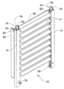
Referring to Figure 1 it will be seen that this illustrates an embodiment of
the invention,
in the form of a shutter (10) having a frame with side members (12) . The
frame will
also have top and bottom members .
Louvres (14) extend from side to side of the frame, at spaced intervals. As is
well
known such louvres (14) are rotatable between open and closed positions.
In simple domestic shutters the louvres are permanently installed in their
frames.
However in this improved form of shutter, the louvres (14) are supported in
individual
drive connectors, which are concealed within the frame , and which can be
raised up
and lowered, in a manner described below.
As is best shown in Figs 2, 3, 4 ,5,6 and 7, the side frame members (12 ) are
four
sided hollow metal channels, in this case. Top and bottom frame members (not
shown)
would normally be provided, and made from the same channel section. The side
frame
members comprise three channel walls (16) and a fourth slotted wall (18)
defining a
lengthwise slot (20)
5
CA 02733485 2011-03-08
1296C111
Louvres (14) are supported between the two side frame members (12 )
Within the hollow side frame members (12 ) there are located a plurality
of drive connector assemblies (22) . The drive connector assemblies (22 ) are
separate from one another and may be slideable up and down within the hollow
side
frame members (12 ),or may be fixed (in a more economical embodiment).
A louvre control member (24 ) extends lengthwise within each side
frame member (12 ).
The louvre control member (24) is an elongated rod, preferably metallic, of
non circular
shape in section.. In this case a square shape is selected for simplicity.
Each of the drive connector assemblies (22) is fitted onto the louvre control
member
(24) , in a manner described below.
Rotation of the louvre control member (24) in a side frame member will control
all drive
connector assemblies (22 ) within that side frame, in a manner described
below.
Each of the drive connector assemblies (22 ) comprises three components.
A first bevel gear (28) is formed integrally on a hollow, generally
cylindrical
body (30 ), having rotational surfaces or bearings (32) at each end .
The first gear (28) is located intermediate the two ends of the body (30)
A central axial opening (34) extends through body (30) . Opening (34) has a
cross
section which is non circular, in this case square, complementing the shape of
the
louvre control member (24) . This allows the louvre control member (24 ) to
pass
through each of the bodies (30) of the first gears (28) of each of the drive
connector
6
CA 02733485 2011-03-08
1296C111
assemblies (22) .
Each of the drive connector assemblies (22 ) has a second bevel gear (42)
formed
integrally with a generally cylindrical body (44 ). In this case the gear (42)
is located at
one end of the body (44) . The body (44) defines a rotational surface
intermediate its
ends, adjacent the second gear, and a bore with a non circular section (48).
The gear tooth rings of the first and second gears mesh for example at right
angles .
The third component of the drive connector assemblies is the housing (50) .
Housing (50) has two first gear support walls (52 ) and (54) . These two walls
are
located in parallel planes spaced apart from one another. First gear support
wall (52 )
defines an arcuate bearing recess (56), describing slightly more than a semi-
circle,
which acts as a bearing for one end of the first gear body (30 ), and
functions to
capture the first gear body, and position it for rotation. The other first
gear support wall
(54) has a circular bearing opening (58) , lying along a common rotation axis
with
bearing recess (56) . Bearing opening (58) receives the other end of first
gear body
(30 ) and supports it for rotation.
An intermediate second gear wall (60) extends between the two first gear
walls, and
lies in a plane normal to them . Second gear wall (60) has a circular bearing
opening (62) , which receives the second gear body (44) . Second gear body
(44)
extends through opening (62) , and opening (62) functions as a bearing to
support
second gear body for rotation.
Housing (50) also has two side walls (64 ) which simply function as guides
within side frame members (12).
7
CA 02733485 2011-03-08
1296C 111
Each of the louvres (14) has an axle pin (66) extending from each end. Axle
pins are
received in bores (48) . Axle pins have a non circular section complementing
the
section of bores (48) of second gear bodies (44).
In one embodiment (Fig 1 and 7), a manual control knob (70) may be mounted on
one of side frame members (12) .
Within side frame member (12), a drive control assembly (22a) is positioned
normal to
the other drive assemblies (22). Knob (70) has a shaft (72) (Fig 7) which
passes
through wall (16) and into the second gear bore (48) of the drive connector
assembly
(22a) . Rotation of knob (70 ) will thus cause rotation of second and first
gears (42 )
and (28) in that drive connector assembly (22a).
Rotation of first gear (28 ) will thus rotate the louvre control member (24) .
Rotation of the louvre control member (24 ) will cause rotation of all the
other first gears
(28) in the remaining drive connector assemblies (22) .
Rotation of the first gears (28 ) will cause rotation of all the second gears
(42 ) and thus
rotate the louvres (14 ) themselves .
In some cases it may be that even the manual control knob (70) is not
required.
Manual rotation of any one of the louvres (14 ) themselves, will cause
rotation of all the
louvres in that shutter.
In another embodiment provision may be made for power operation of the louvre
control member (24) . Such power operation may be desirable, for example, on
shutters that may be awkward to reach for some reason. Remote switching
devices
(not shown) may be used in this case. Such power operation may be provided by
an
8
CA 02733485 2011-03-08
1296C111
electric motor (not shown) mounted on one side member (12) of a shutter, in a
manner somewhat similar to the mounting of knob (70). Remote operation is not
illustrated since it is well known.
Provision may be made to raise (and to lower) the louvres (14 ) within the
side
members. This extra feature may be desired by some consumers, who may wish to
provide for a clear unobstructed view through a window, for example.
This may be achieved ( Fig 1) by raise cords (74 ) within side frame members
(12).
These cords may be operated manually by pulleys (76), shaft (78), pulley (80)
and cord
(82), or may be powered by any suitable means.
The foregoing is a description of a preferred embodiment of the invention
which is given
here by way of example only. The invention is not to be taken as limited to
any of the
specific features as described, but comprehends all such variations thereof as
come
within the scope of the appended claims.
9