Note: Descriptions are shown in the official language in which they were submitted.
CA 02733700 2011-02-10
WO 2010/018359
PCT/GB2009/001907
- 1 -
Method and apparatus for towing offshore wind turbines
The present invention relates to the field of floating wind turbines and, in
particular, to a method and apparatus for moving an offshore floating wind
turbine.
As used herein, the term "floating wind turbine" means a wind turbine
structure of the kind that is designed to float in a body of water when in
use.
Conventional floating wind turbines comprise a buoyant body having at its
upper
end a nacelle, which contains an electrical generator and other components,
and a
rotor. The body is generally long and approximately cylindrical in shape.
Offshore floating wind turbines are very large structures, the body being
typically 100 - 200 metres in length and the rotor blades in the range of 40 ¨
70
metres long. They are assembled on shore or in protected waters and it is a
significant challenge to move them to their desired location out at sea.
One approach is to tow them out to their installation sites through the water,
whilst floating in the same, generally vertical, position in which they are
used. This
prevents the generator from being submerged under water or splashed, which
could
damage its components.
With this method, the choice of an installation site for the wind turbine and
the possible routes thereto are therefore limited by the depth of the water
through
which the wind turbine must pass. If the water in a region is too shallow, the
floating wind turbine cannot be towed through that region making some
installation
sites unreachable, or only reachable via an indirect, longer route.
As an alternative, methods of transporting wind turbines in an essentially
horizontal position are known. However, these methods require a large vessel
on
which the wind turbine is supported in order to keep the delicate rotor and
generator
components away from the water. For example, GB 2423108 discloses mounting
structures, such as offshore wind turbines, using socket foundations. The
mounting
structure is transported to the socket in an essentially horizontal (reclined)
position,
on board another vessel. In another example, GB 2344843 discloses a gravity
securing system for offshore generating equipment. The generating equipment is
= towed to the installation site in an essentially horizontal (reclined)
position, again on
board another vessel. It will be appreciated that the use of such vessels
increases the
CA 02733700 2011-02-10
WO 2010/018359
PCT/GB2009/001907
- 2 -
cost of transporting the wind turbine and their size may also restrict the
choice of
route or installation location.
According to the present invention there is provided a method of moving a
floating wind turbine relative to a body of water, the floating wind turbine
having a
buoyant body with a nacelle at the upper end thereof, the method comprising
floating the floating wind turbine in the body of water and towing the
floating wind
turbine whilst holding the buoyant body in an inclined position whereby the
nacelle
is held clear of the water. (P
Thus, the inventors have recognised that it is possible to float a wind
turbine
while it is transported in such a way that its draught can be significantly
reduced
whilst keeping the delicate components within the nacelle clear of the water.
It can
then be placed into the conventional vertical configuration prior to use. In
this way it
can pass through shallower water than if it were towed in a vertical position,
and the
number of possible installation sites is thereby increased. At the same time,
the need
for a vessel large enough to carry an entire wind turbine is avoided.
The angle of inclination to the surface of the water should be significant in
order to provide a useful reduction in draught. The precise angle of
inclination (from
the surface) can vary depending on the circumstances and may be in the range
of 20
to 60 . Usually 30 to 50 will be appropriate in order to achieve a useful
reduction
in draught whilst keeping the turbine clear of water. These angles represent
the
average angle. It will be apparent that there will be some degree of
oscillation about
the average due to the effect of waves and wind.
The body of the wind turbine forms its support structure. The support
structure typically comprises a lower support structure, which, when
installed, is
generally mostly submerged, and a tower, which, when installed, is generally
above
the water line.
In the present invention, in order to position a floating wind turbine in an
inclined position, a floating member may be attached to the lower support
structure.
The floating member enables the wind turbine system to be positioned and held
in
an inclined position by exerting an upward force on the lower support
structure. The
floating member could be any suitable buoyant structure, for example a
buoyancy
tank. When the wind turbine reaches the installation site, the floating member
may
CA 02733700 2013-10-18
- 3 -
be removed and the wind turbine can assume an essentially vertical position,
suitable for operation. The floating member is therefore preferably
detachable.
although it could remain in place and be ballasted, e.g. by flooding it with
water
It is preferred that whilst the floating wind turbine is inclined, the force
from
the floating member may be adjusted so as to keep the wind turbine in static
equilibrium. The Force may be adjusted by ballasting the floating member. for
example with water.
Additionally or alternatively to the floating member, a weight may be
attached to the tower to Further enable the positioning and holding of the
wind
turbine system in a desired inclined position by exerting a downward Force on
the
tower. If a weight is attached, preferably it should be attached to the tower
just
above the water line in order to minimise the bending moments exerted on the
support structure, which, ilexcessive, could lead to structural damage.
However, it
is most preferred that no such weight should be added, in order to avoid the
wind
turbine system becoming too submerged, which would risk damage to the wind
turbine generator. If a weight is added, for the reasons discussed above in
relation to
the floating member, it is preferred that the weight should be detachable.
The floating member may be attached to the support structure by a line, for
example a wire, chain or cable. In order to move the wind turbine from a
vertical
position to an inclined position, the length of the line may be reduced, for
example
by winching it into the floating member or the support structure.
In addition, a pair of almost horizontal forces (i.e. a couple) may be applied
to the system in order to overcome the righting moment of the wind turbine
whilst it
is positioned at intermediate inclination angles. Such almost horizontal
forces may
be applied, for example, by a tug or (when close to the shore) by a winch with
a wire
fixed on land. In this discussion, an "almost horizontal force" means a force
with a
horizontal component that is significantly greater than its vertical
component.
As noted previously, a wind turbine generator typically comprises a nacelle
and a rotor. The combined centre of gravity of these components is generally
offset
from the longitudinal axis of the support structure. As the centres of gravity
and
buoyancy of the support structure are located close to the longitudinal axis
of the
support structure, the inclined wind turbine may be in an unstable equilibrium
and
CA 02733700 2011-02-10
WO 2010/018359
PCT/GB2009/001907
- 4 -
may tend to rotate about the longitudinal axis of the support structure. This
can be a
problem as it is important to keep the wind turbine generator out of the water
to
avoid damaging it. '
= In order to address this problem, a "crow foot" or "bridle" arrangement
of
lines may be used to attach the line from the floating member to the support
structure. This may be formed of two lines, for example lengths of wire or
cable,
that connect either side of the support structure to the line from the
floating member
to form a Y-shaped arrangement of lines. This will help to ensure rotational
stability
of the system about the longitudinal axis of the support structure.
During tow-out of the wind turbine system, waves may excite the system and
cause it to oscillate. It is desirable to minimise or eliminate any excitation
of the
system to prevent water damage to the generator.
The most energetic waves generally have a period of around 5 to 20 seconds.
Therefore, in order to reduce or eliminate excitation of the system due to
heave
(almost purely vertical displacement of the system), the natural periods of
oscillation
of the inclined system should preferably be outside of the range of
approximately 5
to 20 seconds, i.e. not equal to the period of the most energetic waves.
Preferably,
the natural periods of the system should be greater than 20 seconds. However,
in
some cases, such as where the stiffness of the system is too great for this to
be a
practical choice, some of the natural periods of the system could be less than
5
seconds.
In order to achieve such natural periods of the system and minimize the
dynamic interaction between heave and pitch motions, the distance from the
centre
of gravity to the waterline around the support structure should ideally be
approximately equal to the distance from the centre of gravity to the point of
attachment of the buoyancy tank.
In order to reduce or eliminate excitation of the system due to pitch
(rotation
of the system about its centre of gravity), the centre of buoyancy of the
system
should ideally be close to its centre of gravity.
Thus, it will be seen that the invention in its broadest sense relates to the
provision of a floating wind turbine in an inclined position whereby it can be
towed
CA 02733700 2013-10-18
- 5 -
through water with a lesser draught than if it were in the vertical
configuration in
which it is used, whilst the nacelle remains clear of the water.
The invention also extends to a floating wind turbine in such a configuration
and to one that is adapted to be held in such a configuration by the provision
of one
or more float(s) and optionally one or more weight(s). Furthermore, the
invention
extends to a method of installing an offshore floating wind turbine comprising
constructing the offshore floating wind turbine, transporting it to its
installation site
according to the method previously described, placing the floating wind
turbine into
its vertical configuration and installing it. The last step generally
comprises tethering
or mooring the structure to the seabed.
Also according to the present invention there is provided a floating wind
turbine system, comprising a floating wind turbine and a floating member, the
floating wind turbine comprising a buoyant body which forms a support
structure.
and a wind turbine generator. wherein the floating member is attached to the
support
structure so that the buoyant body is held in an inclined position whilst the
floating
wind turbine is being towed in a body of water.
Preferred embodiments of the invention will now be described by way of
example only and with reference to the following drawings in which:
Fig. 1 illustrates the forces acting on a preferred embodiment of a floating
wind turbine in an inclined position;
Fig. 2 illustrates the forces acting on a preferred embodiment of a floating
wind turbine with a floating member attached thereto;
Fig. 3 illustrates the forces acting on a preferred embodiment of a floating
wind turbine with a floating member attached thereto and almost horizontal
forces
being applied to the system;
Fig. 4 shows the location of the centre of gravity of the system in a
lengthwise vertical cross section of the tower;
Fig. 5 is another vertical cross section through a tower, with a crow's foot
device attached thereto, in a plane orthogonal to that shown in Fig. 4,
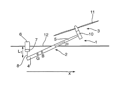
Fig. 1 shows the forces acting on a preferred embodiment of a floating wind
turbine (hereafter "wind turbine") 1 in an inclined position. The wind turbine
1
comprises a support structure 2 and a wind turbine generator 3. The support
CA 02733700 2013-10-18
-
structure 2 comprises a lower support structure 4 and a tower 5. The wind
turbine
generator 3 comprises a nacelle 10 and a rotor 1 I. F0 is the weight of the
wind
turbine 1. FB is the buoyancy force of the wind turbine I.
In order to keep the wind turbine 1 in an inclined position, an upwardly
directed force F1 is required. As illustrated in Fig. 1, F.! should act From a
position
on the lower support structure 4 that is below the centre of gravity of the
wind
CA 02733700 2011-02-10
WO 2010/018359
PCT/GB2009/001907
- 6 -
turbine 1. Optionally, a downwardly directed force F2 acting above the centre
of
buoyancy may also be applied to the wind turbine 1.
The inclined floating position of the wind turbine 1 should be stable. This
requires a stable equilibrium of forces and moments in the vertical plane
through the
longitudinal axis of the support structure 2. Considering the forces indicated
in Fig.
1, this means that:
FB ¨ FG ¨ F2 = 0 (1)
and
¨ FGxG + FBxB ¨ F2x2 =0 (2)
where FB, F1, FG and F2 are defined above and in Fig. 1, and xi, xG, xB and x2
are the
horizontal coordinates of where the forces F1, FG, FB and F2, respectively,
act on the
wind turbine 1.
The forces F1 and F2 could be applied to the wind turbine 1 by, for example,
a buoyancy tank 6 attached to the lower support structure 4, as shown in Fig.
2, and
a clump weight (not shown) attached to the tower 5 close to the water line 12,
respectively. If the clump weight were attached higher up the tower 5, it
would
contribute more effectively with respect to inclining the wind turbine but it
could
introduce large bending moments in the tower 5, which could bend or damage the
structure of the tower 5.
A further problem associated with applying an external force F2 to the wind
turbine 1, is that it can result in an undesirable greater submergence of the
wind
turbine 1 (unless further modifications to its buoyancy are made). It is
therefore
preferred that in most cases F2 should be set equal to zero and no clump
weight or
similar should be attached.
Ideally, the wind turbine 1 should (for this part of the operation) be
designed
such that its centre of gravity G should be as close to the centre of buoyancy
B as
practically possible (see Fig. 2). By positioning G and B as close together as
possible, this reduces the required magnitude of F1. The required magnitude of
F1
can also be reduced by making F1 act on the wind turbine 1 as far down the
lower
support structure 4 as possible, as shown in Fig. 1.
CA 02733700 2011-02-10
WO 2010/018359
PCT/GB2009/001907
- 7 -
As shown in Fig. 2, the buoyancy tank 6 may contain ballast 7, such as
water. By altering the amount of ballast 7 in the buoyancy tank 6, the
magnitude of
force F1 may be adjusted. This may also be achieved by adjusting the length L1
of a
line 8 shown in Figure 2.
The buoyancy tank 6 is connected to the lower support structure 2 via the
line 8. The length of the line 8 may be shortened or lengthened via a winch
(not
shown) attached to either the buoyancy tank 6 or the lower support structure
6. By
winching the line 8 in or out, the depth L1 of the end of the lower support
structure 2
beneath the water line 12 can be varied.
The wind turbine 1 can be placed in an inclined position by adjusting the
length of the line 8 to vary the depth L1 until the wind turbine 1 has the
desired
inclination angle a, as shown in Figure 2.
In order to move the wind turbine 1 from an initial vertical position to an
inclined position for towing, the line 8 is initially relatively long. The
depth L1 is
then reduced by winching in the line 8. Simultaneously, as shown in Fig. 3, a
pair of
almost horizontal forces Flu and FH2 are applied to the wind turbine 1 in
order to
overcome the righting moment of the wind turbine 1 in the intermediate
inclination
angles, while it is being moved from a substantially vertical position, to a
stable
inclined position.
The pair of almost horizontal forces Flu and FH2 can be applied by using a
tug or a winch together with a wire fixed on land, for example. The required
magnitude of these forces Flu and FH2 may be determined by considering the
static
equilibrium of the wind turbine 1 in all inclination angles from 90 degrees to
the
actual inclined position.
The actual inclination angle a is chosen with consideration given to the depth
of the water through which the wind turbine 1 is to be towed, the length of
the wind
turbine 1 below the water line 12 and the height of the nacelle 10 and rotor
11 of the
wind turbine generator 3 above the water line 12. Ideally, the wind turbine 1
should
be in an inclined position such that there is simultaneously sufficient
clearance
above the water line 12 for the nacelle 10 and rotor 11 so that they do not
get wet
and a sufficient reduction in draft.
CA 02733700 2011-02-10
WO 2010/018359
PCT/GB2009/001907
- 8 -
The inclined wind turbine 1 should ideally also be stable with respect to
rotation about its longitudinal axis.
If the wind turbine 1 is towed in an inclined position as illustrated in Fig.
1,
the combined centre of gravity of the nacelle 10 and rotor 11 in most cases
will be
located above the longitudinal axis 13 of the support structure 2. The centre
of
gravity of the support structure 2 is usually located close to the
longitudinal axis 13.
The centre of buoyancy of the support structure 2 is also usually located
close to the
longitudinal axis 13. However, as the combined centre of gravity of the
nacelle 10
and rotor 11 is usually located above the longitudinal axis 13, the centre of
gravity G
of the whole wind turbine 1 is thus also located slightly above the
longitudinal axis
13, as shown in Figure 4. Therefore, any slight movement of the wind turbine 1
about the longitudinal axis 13 will thus tend to cause rotation of the wind
turbine 2
about the longitudinal axis 13. Due to this unstable equilibrium, the wind
turbine 1
would tend to end up in a floating position with the rotor 11 located beneath
the
longitudinal axis 13 and therefore closer to the water line 12, where it may
be more
likely to be splashed by waves, or possibly even submerged.
In order to avoid this happening, the buoyancy tank 6 can be used to
introduce a sufficient righting moment to compensate for the moment introduced
by
the asymmetry of the weight distribution of the wind turbine 1 about the
longitudinal
axis 13.
As illustrated in Fig. 4, the centre of buoyancy B of the wind turbine 1 is
located approximately on the longitudinal axis 13 and the centre of gravity G
of the
wind turbine 1 is located a distance yo from the axis 13. When the support
structure
2 is inclined at an angle a to the horizontal, there is a moment MG from the
weight of
the wind turbine 1 about the axis 13, which can be written as follows:
MG = -0mgyG cos a (3)
where m is the mass of the wind turbine 1, g is the acceleration due to
gravity and 0
is the angle of rotation about the axis 13. 0 is assumed to be small in the
stability
considerations. The negative sign indicates that the moment MG is
destabilising.
The moment MG may be compensated for by a moment from the buoyancy
force F1 (and possibly the Weight F2, if present). The buoyancy tank 6 can be
CA 02733700 2011-02-10
WO 2010/018359
PCT/GB2009/001907
- 9 -
connected to the support structure by a single line 8 at a distance yF from
the axis 13.
The righting moment MF1 from the buoyancy force F1 can then be written as
follows:
MFI = Fly F cos a . (4)
In order for the system to be stable with respect to rotation about the axis
13,
this therefore requires that:
MFi +MG > 0 (5)
and
FIY F > IVY G = (6)
In most cases mg >> F1. Therefore, according to requirement (6), it should
be required that yF >> yG in order to ensure stability. If yF is not
sufficiently large, it
may be increased by using a crow foot 9 at the end of the line 8 between the
buoyancy tank 6 and the support structure 2, as shown in Fig. 5.
When a crow foot 9 is used, the moment MFI about the axis 13 from the
buoyancy force F1 can be written as follows:
MF, = OFIr cos a (7)
where r is the vertical distance from the axis 13 of the support structure 2
to the top
point 14 of the crow foot 9. As r> yF, the rotational stability of the system
about the
axis 13 is increased by using the crow foot 9.
Equation (7) is valid when 6t os a < tan/3 (assuming small rotation angles 0),
where fi is half of the angle between the two lines 15 of the crow foot 9, as
indicated
in Fig. 5. If the rotation angle 0 exceeds tanfl/cosa, then one of the lines
15 of the
crow foot 9 will become slack and the effect of the crow foot 9 will
disappear.
However, as the rotation angle 0 is generally small, the crow foot 9 can be an
effective means for achieving the required stability in relation to rotation
about the
axis 13 of the support structure 2.
Stability may also be obtained or improved by adjusting the position of
internal ballast contained within the support structure 2. In this way, yG<0
(i.e. the
centre of gravity being located beneath the longitudinal axis 13 of the
support
structure 2) may be obtained.
CA 02733700 2011-02-10
WO 2010/018359
PCT/GB2009/001907
=
-
As well as the static stability of the system, it is also important to
consider its
dynamic stability. Waves can be the most important sources of dynamic
excitation
during tow-out of a wind turbine 1. The dynamic response of the wind turbine 1
should ideally be limited as much as possible in order to avoid possible
wetting of
5 the nacelle 10 and rotor 11 and in order to limit the possible dynamic
load on the
tower 5 and lower support structure 4.
A full assessment of the dynamic loads on the system caused by waves
requires a coupled dynamic analysis, where the effect of the wind turbine 1
itself,
the buoyancy tank 6 and possible clump weight, as well as all wire
arrangements
10 including the towing wire are included in the analysis. The wave forces,
hydrodynamic mass and damping should also be considered.
However, in general, it is important for the natural periods of the system to
be outside of the range of periods of the most energetic waves, i.e. outside
of the
range of approximately 5 to 20 seconds.
An initial estimate of the system's natural periods can be obtained by
considering an uncoupled system. The parameters of the buoyancy tank 6 and its
location can then be adjusted so that requirements for both static and dynamic
equilibrium are fulfilled.
Heave motion is an almost entirely vertical displacement of the system. The
inertia M33 involved in such an oscillation can be written as follows:
M33 = /71 + A33 /7/ pV COS 2 a (8)
where M33 is the effective mass for vertical heave oscillations, m is the
total dry
mass of the system (including the buoyancy tank 6 and possible clump weight),
A33
is the hydrodynamic mass in heave of the support structure 2 and pV is the
mass of
the displaced water. For simplicity, it is assumed that the displacement and
added
mass of the buoyancy tank and possible clump weight are much less than the
corresponding values for the wind turbine 1.
The restoring force coefficient C33 in the heave direction can be determined
from the water plane area of the inclined support structure 2 and the buoyancy
tank
6 as follows:
CA 02733700 2011-02-10
WO 2010/018359
PCT/GB2009/001907
- 11 -
C33 = pg(nR2
+ A1) (9)
cos a
where R is the radius of the support structure 2 (which, for simplicity, is
assumed
here to have a circular cross section) and A1 is the water plane area of the
buoyancy
tank 6.
=
The natural period 7'3 of the system for a pure, un-damped heave motion can
then be written as follows:
73 27r11A1 3 (10)
C33
In order to avoid the range of periods of the most energetic waves (i.e. from
about 5 to 20 seconds), T3 should ideally be greater than about 20 seconds.
In order to avoid too strong coupling between heave and pitch, the two terms
in equation (9) for C33 should be approximately equal. Moreover, the distance
from
centre of gravity G to the water line 12 of the support structure 2 should be
approximately equal to the distance from centre of gravity G to the point of
=
attachment of the buoyancy tank 6 to the support structure 2. In other words,
as
shown in Fig. 3, the centre of gravity G should be about halfway between the
point
of attachment of the buoyancy tank 6 to the support structure 2 and the point
where
the support structure 2 passes through the water line 12.
It is also important to consider pitch. M55 is the contribution to the inertia
of
the system due to pitch rotation around the centre of gravity G of the wind
turbine 1
and it can be written as follows:
M55 = /55 + A" 2. 155
+ _1 P 2 L3 prR 2 WG )2
(1 1)
12
where /55 is the moment of inertia of the wind turbine 1 about the centre of
gravity G
and A55 is the hydrodynamic inertia of the submerged part of the support
structure 2.
The approximate expression given in the second part of equation (11) is
obtained by
assuming the support structure 2 is a long, slender cylinder with a constant
radius.
The coordinate is measured along the axis 13 of the support structure 2 such
that x
= cos a. L is the length of the submerged part of the support structure 2.
In a similar way, the pitch restoring coefficient C55 can be written as
follows:
CA 02733700 2011-02-10
WO 2010/018359
PCT/GB2009/001907
- 12 -
pyrR 2
C55 = pgAi(x.G x.F. + _______________ (xG xffs )2 (12)
cos a
where xwL is the x-coordinate of the centre of the water plane area of the
support
structure 2.
The natural period of the system in pitch T5 can then be written as follows:
T5 27r 11/ . (13)
C55
If the system is not approximately symmetric about the centre of gravity G of
the wind turbine 1, the coupled heave-pitch equations of the system should be
solved. This would involve coupled inertia and restoring terms of the form M35
and
C35.
As with the case for heave, and for the same reasons, ideally T5> 20
seconds. However, in certain cases, for example where the stiffness of the
system is
particularly large, T5 <5 seconds would be a more practical choice.
From equation (12), it can be seen that the symmetry of the system would be
improved if:
7TR2
A1- . (14)
cos a
Furthermore, the moment of inertia /55 in equation (11) should have a minimum
value close to centre of gravity G. This requirement is generally fulfilled
for the
contribution related to the dry mass of the system. It will also be
approximately
fulfilled for the hydrodynamic mass of the system if the centre of buoyancy B
is
close to the centre of gravity G.
A further type of motion that should be considered is roll. Roll about the
axis 13 of the support structure 2 is generally only weakly coupled to the
other
modes of motion (heave and pitch). The inertia in roll generally has only an
insignificant contribution from hydrodynamic effects. This means that roll
inertia
M44 can be written as follows:
M44 = 144 A44 144.(15)
The restoring effects against roll come from the possible clump weight and
the buoyancy tank 6, as discussed above. For small roll angles it can be
assumed
CA 02733700 2011-02-10
WO 2010/018359
PCT/GB2009/001907
- 13 -
that the buoyancy force F1 remains approximately constant. (The same is also
true
for F2).
Considering only the buoyancy tank 6, and not a possible clump weight, the
roll restoring force C44 can be written as follows:
5C44 = ¨mgyG + Fir cosa (16)
and the natural period in roll T4 can then be written as follows:
T4 274¨M44= (17)
C44