Note: Descriptions are shown in the official language in which they were submitted.
CA 02734027 2011-03-14
MULTI-LEVEL SOFA HINGE FOR SOFA CONVERTIBLE
TECHNICAL FIELD
The present invention relates to sofas, and more particularly to a sofa hinge
used for converting a sofa into multiple positions.
BACKGROUND OF THE INVENTION
This section provides background information to facilitate a better
understanding of the various aspects of the present invention. It should be
understood
that the statements in this section of this document are to be read in this
light, and not
as admissions of prior art.
I 0 A sofa is
an upholstered item of furniture for the comfortable seating of more
than one person and typically has an armrest on both sides of the sofa along
with a
back rest. Sofas are usually to be found in the family room, living room, den
or the
lounge. They are covered in a variety of textiles or in leather.
Sofas may be designed to be convertible into different positions, such as a
lounge position or a bed position in addition to the sofa position. A hinge,
which
connects the sofa seat with the back rest of the sofa, is used to mechanically
allow the
operator of the sofa to switch the sofa from one position to another. Often, a
hinge is
placed on each side of the sofa. Hinges that are used to convert a sofa into
multiple
positions may be referred to as a "click clack mechanism" due to the clicking
sound
that is made when the sofa is converted into a new position.
Currently, the design of these types of hinges includes an exposed gear
mechanism which may potentially snap an operator's finger while the operator
transitions the sofa from one position to another.
Therefore, there is a need in the art for a sofa hinge that provides easy
conversion of the sofa from one position to another while providing added
safety by
substantially reducing the risk of an injury to the operator's fingers.
40285-P021US Page 1 of 13 PATENT
CA 02734027 2011-03-14
BRIEF SUMMARY OF THE INVENTION
In one embodiment of the present invention, a sofa hinge comprises a first
bracket and a second bracket, where the second bracket comprises a semi-
circular
portion and where the first and second brackets are rotatably connected
together via a
first bolt. The sofa hinge further comprises a lever connected to the first
bracket via a
first lever latch on the first bracket. The lever is connected to the second
bracket via a
second lever latch on the second bracket. Additionally, the lever comprises a
plurality of notches, where the first lever latch is bolted to an end of the
lever and
where the second lever latch comprises a pin used to select one of the
plurality of
notches of the lever to select a position of a sofa. In addition, the sofa
hinge
comprises a cover plate rotatably connected to the first bolt, where the cover
plate
comprises a semi-circular portion and where the cover plate covers at least a
portion
of the semi-circular portion of the second bracket in various positions of the
sofa.
Furthermore, the semi-circular portion of the second bracket covers a portion
of the
lever in various positions of the sofa.
In another embodiment of the present invention, a sofa comprises a sofa seat
and a back rest. Furthermore, the sofa comprises a hinge rotatably connecting
the
sofa seat with the back rest. The sofa hinge comprises a first bracket and a
second
bracket, where the second bracket comprises a semi-circular portion and where
the
first and second brackets are rotatably connected together via a first bolt.
The sofa
hinge further comprises a lever connected to the first bracket via a first
lever latch on
the first bracket. The lever is connected to the second bracket via a second
lever latch
on the second bracket. Additionally, the lever comprises a plurality of
notches, where
the first lever latch is bolted to an end of the lever and where the second
lever latch
comprises a pin used to select one of the plurality of notches of the lever to
select a
position of the sofa. In addition, the sofa hinge comprises a cover plate
rotatably
connected to the first bolt, where the cover plate comprises a semi-circular
portion
and where the cover plate covers at least a portion of the semi-circular
portion of the
second bracket in various positions of the sofa. Furthermore, the semi-
circular
40285-P021US Page 2 of 13
PATENT
CA 02734027 2011-03-14
portion of the second bracket covers a portion of the lever in various
positions of the
sofa.
The foregoing has outlined rather generally the features and technical
advantages of one or more embodiments of the present invention in order that
the
detailed description of the present invention that follows may be better
understood.
Additional features and advantages of the present invention will be described
hereinafter which may form the subject of the claims of the present invention.
40285-P021US Page 3 of 13 PATENT
CA 02734027 2011-03-14
BRIEF DESCRIPTION OF THE SEVERAL VIEWS OF THE DRAWING
A better understanding of the present invention can be obtained when the
following detailed description is considered in conjunction with the following
drawings, in which:
Figure 1 is an elevation view of a multi-level sofa hinge for a sofa
convertible
in accordance with an embodiment of the present invention;
Figure 2 illustrates an external view of the multi-level sofa hinge for a sofa
convertible in accordance with an embodiment of the present invention;
Figures 3A-3B illustrate a sofa hinge a sofa according to one or more aspects
of the present invention in a released, or unlocked, position permitting the
first
bracket and second bracket, and therefore the back and seat platforms of the
sofa, to
move relative to one another;
Figures 4A-4B illustrate a sofa hinge and a sofa secured in a sofa position in
accordance with an embodiment of the present invention;
Figures 5A-5B illustrate a sofa hinge and a sofa secured in a lounge position
in accordance with an embodiment of the present invention; and
Figures 6A-6B illustrate a sofa hinge and a sofa secured in a sofa bed
position
in accordance with an embodiment of the present invention.
40285-P021US Page 4
of 13 PATENT
CA 02734027 2011-03-14
DETAILED DESCRIPTION OF THE INVENTION
The present invention comprises a sofa hinge that includes a first and a
second
bracket rotatably connected to the sofa hinge at a bolt. The second bracket
includes a
semi-circular portion that covers a portion of the lever during the various
positions
(e.g., lounge, sofa, sofa bed) of the sofa. The lever is bolted to the first
and second
brackets via a first and second lever latch on the first and second bracket,
respectively. The second lever latch includes a pin which is used to select a
particular
notch of the lever to select a position of the sofa. The sofa hinge further
includes a
cover plate rotatably connected to the sofa hinge at the bolt. The cover plate
includes
a semi-circular portion and is adjacent to the semi-circular portion of the
second
bracket. The cover plate covers at least a portion of the semi-circular
portion of the
second bracket in various positions of the sofa. By having the cover plate
conceal the
gear mechanism of the sofa hinge, the risk of injury to the operator's fingers
is
substantially reduced.
It is to be understood that the following disclosure provides many different
embodiments, or examples, for implementing different features of various
embodiments. Specific examples of components and arrangements are described
below to simplify the patent disclosure. These are, of course, merely examples
and
are not intended to be limiting.
As discussed in the Background section, currently, the design of click-clack
mechanisms includes an exposed gear mechanism which may potentially snap an
operator's finger while the operator transitions the sofa from one position to
another.
Therefore, there is a need in the art for a sofa hinge that provides easy
conversion of
the sofa from one position to another while providing added safety by
substantially
reducing the risk of an injury to the operator's fingers.
The sofa hinge of the present invention provides easy conversion of a sofa
convertible from one position to another while providing added safety by
substantially reducing the risk of injury to the operator's fingers as
discussed below in
connection with Figures 1-2, 3A-3B, 4A-4B, 5A-5B and 6A-6B. Figure
1 is an
40285-P021US Page 5 of 13 PATENT
CA 02734027 2011-03-14
internal view of the sofa hinge, which may also be referred to as a "click-
clack
mechanism." Figure 2 illustrates an external view of the sofa hinge. Figures
3A-3B
illustrate a sofa hinge and a sofa when the sofa is secured in the release
position.
Figures 4A-4B illustrate the sofa hinge and sofa when the sofa is secured in
the sofa
position. Figures 5A-5B illustrate the sofa hinge and sofa when the sofa is
secured in
the lounge position. Figures 6A-6B illustrate the sofa hinge and sofa when the
sofa is
secured in the sofa bed position.
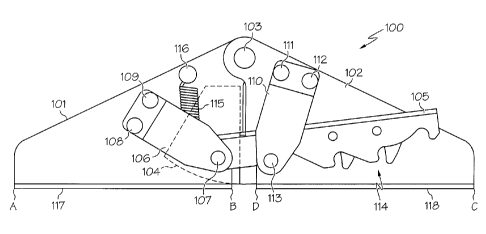
Referring to Figure 1, Figure 1 is an internal view of a sofa hinge 100 in
accordance with an embodiment of the preset invention. Sofa hinge 100 includes
brackets 101, 102 which are rotatably connected together via a bolt 103.
Bracket
102 further includes a semi-circular portion 104 which covers a portion of
lever 105
(from an external perspective as shown in Figure 2) during the various
positions (e.g.,
lounge, sofa, sofa bed) of the sofa.
Sofa hinge 100 further includes lever 105 which is connected to bracket 101
via a lever latch 106. In particular, lever latch 106 is bolted to lever 105
at one end
of lever 105 at bolt 107. Lever latch 106 may be bolted to bracket 101 via
bolts 108,
109.
Lever 105 is connected to bracket 102 via a lever latch 110. Lever latch 110
may be bolted to bracket 102 via bolts 111, 112. Furthermore, lever latch 110
includes a pin 113 used to select one of the notches 114 of lever 105 to
select a
position of the sofa. As pin 113 selects a particular notch 114 of lever 105,
a
"clicking" sound is heard which provides an indication to the operator that a
new
position of the sofa (e.g., lounge, sofa, sofa bed) has been established.
Additionally, sofa hinge 100 may include a spring 115 connected to an end of
lever 105 where spring 115 is bolted to bracket 101 via bolt 116.
In one embodiment, the distance of bracket 101 from the end identified as "A"
in Figure 1 to bolt 113 is about 5 1/2 inches in length. In one embodiment,
bracket
101 includes a flap 117 extending from the end labeled as "A" in Figure 1 to
the end
40285-P021US Page 6 of 13 PATENT
CA 02734027 2011-03-14
labeled as "B" in Figure 1. In one embodiment, the distance of flap 117 from
end A
to end B is about 4 3/4 inches in length.
In one embodiment, the distance of lever 105 from bolt 107 to the opposite
end of lever 105 is about 5 inches in length.
In one embodiment, the distance of bracket 102 from the end identified as "C"
in Figure 1 to bolt 113 is about 5 1/2 inches in length. In one embodiment,
bracket
102 includes a flap 118 extending from the end labeled as "C" in Figure 1 to
the end
labeled as "D" in Figure 1. In one embodiment, the distance of flap 118 from
end C
to end D is about 4 3/4 inches in length.
A description of the external view of sofa hinge 100 is provided below in
connection with Figure 2.
Referring to Figure 2, in conjunction with Figure 1, Figure 2 illustrates an
external view of sofa hinge 100 in accordance with an embodiment of the
present
invention. Components of sofa hinge 100 that are shown on both the internal
(Figure
1) and external (Figure 2) views have the same identification number.
As illustrated in Figure 2, sofa hinge 100 includes a cover plate 201 that
includes a semi-circular portion 202. Cover plate 201 is rotatably connected
to sofa
hinge 100 via bolt 103. In one embodiment, cover plate 201 covers at least a
portion
of semi-circular portion 104 of bracket 102 in various positions of the sofa.
By
having cover plate 201 conceal the gear mechanism of sofa hinge 100, the risk
of
injury to the operator's fingers is substantially reduced.
In one embodiment, cover plate 201 is adjacent to semi-circular portion 104 of
bracket 102. In one embodiment, the horizontal distance between the end
labeled as
"A" in Figure 2 to the end labeled as "B" in Figure 2 is about 5 1/2 inches in
length.
A description of the various configurations of sofa hinge 100 during the
different positions of the sofa is described below in connection with Figures
3A-B,
4A-B, 5A-B and 6A-B.
40285-P021US Page 7 of 13 PATENT
CA 02734027 2013-05-13
Referring to Figure 3A, in conjunction with Figures 1 and 2, Figure 3A
illustrates the configuration of sofa hinge 100 when the sofa (shown in Figure
3B) is
in the release position in accordance with an embodiment of the present
invention.
As illustrated in Figure 3A, semi-circular portion 202 of cover plate 201
provides
protection of an operator's fingers from the gear mechanism of sofa hinge 100.
Referring to Figure 3B, Figure 3B illustrates a sofa 300 when in the release
position in accordance with an embodiment of the present invention. As
illustrated in
Figure 3B, sofa hinge 100 may rotatably connect a sofa seat 301 with a back
rest 302
residing in areas labeled as "A" and -B" in Figure 3B.
Referring to Figures 4A-B, in conjunction with Figures 1 and 2, Figure 4A
illustrates the configuration of sofa hinge 100 when sofa 300 is in the sofa
position as
illustrated in Figure 4B in accordance with an embodiment of the present
invention.
As illustrated in Figure 4A, semi-circular portion 202 of cover plate 201
provides
protection of an operator's fingers from the gear mechanism of sofa hinge 100.
Referring to Figures 5A-B, in conjunction with Figures 1 and 2, Figure 5A
illustrates the configuration of sofa hinge 100 when sofa 300 is in the lounge
position
as illustrated in Figure 5B in accordance with an embodiment of the present
invention.
Referring to Figures 6A-B, in conjunction with Figures 1 and 2, Figure 6A
illustrates the configuration of sofa hinge 100 when sofa 300 is in the sofa
bed
position as illustrated in Figure 6B in accordance with an embodiment of the
present
invention.
Although the sofa and hinge are described in connection with several
embodiments, the scope of the claims should not be limited by the preferred
embodiments set forth in the examples, but should be given the broadest
interpretation consistent with the description as a whole.
Page 8 of 13