Note: Descriptions are shown in the official language in which they were submitted.
- 1 ¨ =
pMDI INHALER COMPRISING FLUTICASONE AND SALMETEROL
This invention relates to metered dose inhalers for the administration of
active
medicaments/propellants and excipients from pressurised aerosol cans
(pressurised
Metered Dose Inhalers) such inhalers are commonly termed, "pMDIs" and, more
particularly, to metered dose inhalers for the simultaneous administration of
mixtures of
active medicaments.
There have been many paper proposals for pMDIs but only two basic designs
have actually achieved any extended use. In the first of these, an example of
which is
the GSK "Evohaler" (herein "EH"), a pMDI can is mounted in a plastic tubular
case
with a mouthpiece at one end, commonly known as the actuator. The user inserts
the
mouthpiece into his mouth and, as he inhales, he depresses the distal end of
the can,
thus releasing a metered dose of active into the inhaled air.
These devices are relatively simple in construction and, hence, relatively
inexpensive to manufacture. However, they are not easy to use and patients
often need
skilled assistance and training to be able to use them reasonably well (see,
for example,
Giraud et al. Misuse of corticosteroid metered-dose inhaler is associated with
decreased
asthma stability. Eur Respir J. 2002 Feb; 19(2):246-51; and Cochrane MG, Bala
MV,
Downs et al. Inhaled corticosteroids for asthma therapy: patient compliance,
devices,
and inhalation technique. Chest. 2000 Feb; 117(2): 542-50). A major problem is
for the
user to co-ordinate efficiently his breath intake with release of the active.
To try to deal with this problem, it is known to have a spacer device on the
mouthpiece so that the released aerosol passes into the spacer from which the
patient
can inhale it (see, for example, British Guidelines on the management of
bronchial
asthma. BTS/SIGN July 2007 update; and Expert Panel Report. 3 (EPR-3):
Guidelines for the Diagnosis and Management of Asthma-Summary Report 2007, The
Journal of allergy and clinical immunology. 2007 Nov:120(5 Suppl): S94-138).
The use of
a large spacer is generally very effective, but is a nuisance to the user
since it is bulky and
must be fitted to the pMDI on every occasion for use.
Another approach to assisting with the problem of co-ordination has been to
provide breath-actuated inhalers. In these, a patient simply inhales through
the
CA 2734135 2020-03-12
CA 02734135 2011-02-14
WO 2010/007361 PCT/GB2009/001740
-2-
mouthpiece of the device and, as inhalation begins, the device automatically
releases the
drug into the air stream. One example of such a device is "Easi-Breathe"
(herein "EB")
which may also be used with a small spacer, particularly with Inhaled
Corticosteroids.
Both these types of device (ie the EH and the EB) emit the aerosol for
inhalation
at a flow rate somewhat greater than the normal inhalation flow rate of a
patient. A
result of this is that the aerosol impacts the back of the patient's throat
and some of the
medicament, especially larger droplets or particles, will deposit there rather
than
passing into the lungs. This undesirable effect can be obviated if a large
spacer is used
with EH, but the small spacer of EB does not slow the gas flow very much. High
gas
flow emission resulting in some deposition of medicament in the throat is not
only
uncomfortable for patients but also, in the case of actives such as steroids,
can lead to
very undesirable side effects, local and systemic.
It has been proposed to slow down the exit flow rate of a pMDI by including a
vortex-producing device in the gas flow path (see eg EP 0308524B) together
with an
integral horn outlet from the vortex device, so that the net result is that
any tendency in
the aerosol for particle agglomeration is reduced in the vortex, and the final
exit flow
rate from the horn is very low. In this way, throat deposition can be much
reduced due
both to the low exit flow rate and to the reduced quantity of larger particles
in the
inhaled aerosol. In such pMDIs, separate spacers are not required since it has
been
shown that the same clinical effect is obtained with these pMDIs as when a
conventional pMDI is used with a spacer (Menzies et al. An in vitro and in
vivo
comparison of inhaled steroid delivery via a novel vortex actuator and a
conventional
valved holding chamber. Ann Allergy Asthma Immunol. 2007;98:471-479).
A further proposal which has been made is to provide a pMDI which, in one
unitary device, includes a combination of a vortex device, a horn and breath-
actuation
means in order to try to combine the advantages individually attributable to
the various
components. Examples of such proposed inhalers are shown in our WO 2005/007226
and WO 2007/066140, to which reference should be made for further details.
These
novel pMDI inhalers are known as "SYNCHRO-BREATHE" inhalers (herein "SB").
("SYNCHRO-BREATHE" is a trade mark.)
We have now been able to investigate the use of SB inhalers by testing them in
a
-3-
variety of critical conditions and have found them to be, very surprisingly,
much more
advantageous than the prior known devices, with and without their associated
spacers.
For example, Nair et al (British Journal of Clinical Pharmacology, (July 2008,
Vol 66, Issue I, pages 20-26) describe an in vivo study in mild to moderate
asthmatics
to compare the respirable dose delivery of hydrofluoralkane fluticasone
propionate
(HFA-FP) via an optimally prepared Aerochamber PIusTM spacer (AP), via an SB
device, and via a pMDI EH. It was found that the use of the optimally prepared
AP
and the use of the SB device, when compared to the EH device, both
significantly
increased respirable dose of HFA-FP. Whilst according to the particular
criteria used
in this in vivo study, the improvement in respirable dose was numerically
greater for
the AP then for the SB device, over the EH device, several factors need to be
borne in
mind in comparing the pMDI/AP combination with the SB. Firstly, considerable
effort
was made to ensure that the AP spacer was used under optimal conditions
(spacer pre-
washed and primed to reduce electrostatic charge, as well as using single
puffs without
inhalation delay), and in practical use patients rarely if ever make these
preparations
before use of the spacer. Thus, it is very likely that the spacer will operate
much less
efficiently in ordinary usage than in this study. Secondly, the requirement
for the
patient to carry round a spacer for occasional use by assembly with their pMDI
is a
considerable nuisance to the patient (and, in the case of children, to their
parents),
whereas there is no such problem with an SB device. For these and other
reasons, the
SB device is highly advantageous not only over a conventional pMDI such as EH,
but
also over a pMDI/spacer combination such as pMDI/AP spacer. Reference should
be
made to the Nair et al paper above for further details.
It is well established that there can be significant differences in the in
vitro drug
delivery characteristics (e.g. Andersen Cascade Impactor test results) between
different
pMDI's, different spacers and different inhalation drugs. The fact that one
particular
pMDI device gives good in vitro results with one particular medicament does
not mean
that the same pMDI will give similarly good in vitro results with another
different
medicament, nor that the same medicament will necessarily be successful in in
vitro
tests with a different pMDI. The same is equally true of the use of different
pMDI/spacer combinations.
CA 2734135 2017-07-17
CA 02734135 2011-02-14
WO 2010/007361
PCT/GB2009/001740
-4-
Furthermore, and very importantly, whilst in vitro tests can serve as a guide
to
likely in vivo test results, they are not a totally reliable guide. Superior
in vitro test
results do not necessarily mean that better in vivo clinical results will be
obtained.
Furthermore, we have found that the excellent in vivo results obtained with FP
in SB (as
referred to above) were certainly not expected in light of the in vitro
results. The in
vivo results showed the SB to be far more advantageous than the in vitro
results
indicated.
It is known to administer a combination of the corticosteroid fluticasone
propionate (FP) and the long-acting beta-agonist salmeterol xinafoate (SM)
using a
conventional pMDI inhaler such as EV. This use of so-called combination
inhalers
provides the dual benefit of targeting airway inflammation and bronchodilation
with a
single device, thus potentially encouraging patient compliance. This use
of
combination inhalers (with or without spacers) results in clinically relevant
improvements in symptoms, lung function, and exacerbations, and is superior
when
compared to doubling the dose of inhaled corticosteroid in asthmatics.
We have now found that, in in vivo tests, the use of an SB device surprisingly
results in commensurate increases in the respirable drug delivery of both or
all the
moieties in a mixture thereof such as FP/SM, for example, compared to a
conventional
EV pMDI device alone. It is surprising to find that, with the SB device, the
respirable
dose delivery of both or all the medicaments in a mixture is simultaneously
improved.
A significant potential advantage of this is that it enables a clinician to
reduce the
overall dose of actives administered, thereby increasing the so-called
'benefit/risk
ratio'.
In one aspect, therefore, the invention provides a pMDI inhaler which includes
a
pMDI canister, a vortex device, an integral horn and a breath-activating
mechanism,
wherein the canister contains a formulation comprising a combination of two or
more
active medicaments.
The inhalers of the invention contain a conventional pMDI canister mounted to
release a metered dose of its contents, upon actuation, into a vortex-
generating device to
generate turbulent vortices in the flowing aerosol. Examples of such devices
and their
use in pMDI inhalers are given, for example, in EP 0308524A. A very important
effect
CA 02734135 2011-02-14
WO 2010/007361
PCT/GB2009/001740
-5-
of the vortex-formation is to reduce any tendency for larger particles or
droplets to form
in the aerosol.
The aerosol then passes into one end of an integral horn, the other end of
which
forms the mouthpiece for the inhaler. The shape of the horn is such as to
widen towards
the mouthpiece end, thus effectively significantly reducing the flow rate of
the aerosol.
At the mouthpiece end, the aerosol will have a low exit flow rate. To this
extent, the
horn replaces the spacers used with previous devices, and since the horn is an
integral
part of the inhalers of the invention and of relatively small size, there are
significant
advantages to the patient in portability and use of the inhaler. There are
many suitable
shapes and arrangements of horn which may be used. Some are shown, by way of
example only, in our WO 2005/007226, WO 2007/066140 and in Fig. 7 of EP
0308524.
The SB inhaler also includes a breath-actuating mechanism so that release of
the
metered dose of medicaments occurs in response to initiation of intake of
breath
through the horn by the user. There are many possible breath-actuation
arrangements
for pMDI inhalers: examples of suitable arrangements are shown, for example,
in our
WO 2005/007226 and WO 2007/066140.
The advantages of the present invention are obtained with any combination of
medicaments to be administered by pMDI. The invention is thus useful, for
example,
with combination products of an inhaled corticosteroid (ICS) and a long-acting
beta-
agonist (LABA). Examples of ICS include beclomethasone, budesonide,
ciclesonide,
fluticasone and mometasgne, and examples of LABA include formoterol and
salmeterol. A particularly preferred combination is that of fluticasone and
salmeterol
(FP/SM). Such mixtures are marketed in pMDI canisters by GSK under the trade
mark
"Seretide". They
comprise fluticasone propionate and salmeterol xinafoate in
HFA-134a propellant. The invention is also useful, for example, with
combination
products of a short-acting beta-agonist (SABA) and an anticholinergic (AC).
Examples
of SABA include salbutamol, terbutaline and fenoterol, and examples of AC
include
ipratropium and tiotropium. The invention is also useful, for example, with
triple
combination products of, for example, ICS/LABA/AC. Specific examples include
fluticasone/salmeterol/tiotropium and budesonide/formoterol/tiotropium.
The SI3, inhalers of the invention are not only generally very acceptable to
-6-
patients for the administration of the inhaled mixture of medicaments, but
they are also
extremely effective in achieving lung deposition. Indeed, tests have shown
that lung
deposition can be very significantly improved compared with conventional
devices. The
achievement of improved lung deposition has a number of advantages. For
example,
firstly the treatment will generally be more effective the greater the lung
deposition.
Secondly, greater lung deposition from an administered dose gives the
possibility of
administering a lower dose whilst still achieving conventional levels of lung
deposition.
Administration of lower doses in itself is advantageous in minimising side
effects,
especially with steroids.
Accordingly, in a further aspect, the invention provides the use of the SB
inhalers
of the invention to administer simultaneously a mixture of medicaments, such
as
fluticasone and salmeterol, to achieve improved lung deposition per dose of
medicament.
In another aspect, there is provided a pMDI inhaler comprising a pMDI
canister,
a vortex device, an integral horn and a breath-activated mechanism, wherein
the
canister contains a formulation for the treatment of asthma comprising a
combination of
two or more active medicaments, wherein the two or more active medicaments
comprise a combination of an inhaled corticosteroid (ICS) and a long-acting
beta-
agonist (LABA).
In another aspect, there is provided a pMDI inhaler comprising a pMDI
canister,
a vortex device, an integral horn and a breath-activated mechanism, wherein
the
canister contains a formulation for the treatment of asthma comprising a
combination of
two or more active medicaments, wherein the formulation comprises a
combination of
fluticasone and salmeterol.
In order that the invention may be more fully understood, the following
experimental results are given.
Experimental Results
An in vitro (Andersen Cascade Impactor) test was carried out, using EV and SB,
with pMDI containing a fluticasone 250 g/salmeterol 25 [tg combination
suspended in
CA 2734135 2020-03-12
- 6a -
,
HFA propellant. In these tests, the fluticasone moiety showed a fine particle
dose of 93.4
p.g in EH, and 113.1 ktg in SB. The salmeterol moieties were 9.8 Kg in EV and
11.0 jig in
SB. This represents a 21% improvement in SB over EV for fluticasone and a 12%
improvement in SB over EV for salmeterol.
An in vivo deposition study was carried out in healthy volunteers using a
randomised
double blind, double dummy crossover design. Single doses of placebo or
"Seretide"
HFA 250 (total dose ex-valve: fluticasone 2000 mcg/salmeterol 200 meg) were
administered via SB, EH and via a 750 ml plastic spacer "Volumatic" (VM). As
there is
no absorption of fluticasone from the gut, any absorption detected in the
systemic
circulation will by definition solely reflect the lung bioavailability, which
is in turn
determined by the dose delivered to the lungs. The degree of lung
bioavailability of
fluticasone may be reliably quantified by measuring the amount of adrenal
CA 2734135 2020-03-12
CA 02734135 2011-02-14
WO 2010/007361
PCT/GB2009/001740
-7-
suppression relative to baseline, as measured by the ratio for overnight
urinary
cortisol/creatinine (OUCC) excretion, ie the lower the. ratio of suppression,
the greater
the lung deposition for a given device. The swallowed fraction of salmeterol
contributes to 28-36% of its systemic bioavailability, so its systemic
bioavailability
depends predominantly, but not entirely, on lung absorption. It is measured as
serum
potassium. Baseline serum K was collected and was repeated one hour post study
drug
inhalation to measure the early fall in K (which predominantly reflects lung
rather than
gut absorption). The results showed that SB resulted in a commensurate
increase in the
respirable drug delivery of both moieties of FP/SM in combination versus EH
alone,
and was comparable to the 750 ml large volume plastic Volumatic spacer. In
particular,
the geometric mean fold suppression ratios for fluticasone were: EH 1.51, VM
2.52,
SB 2.66, equating to 33.8%, 60.2% and 62.3% suppression, respectively. The
falls in K
were: EH -0.09, VM -0.27, SB -0.32, equating to 2.2%, 6.8% and 8.06% falls,
respectively. There were no significant differences between SB and VM but the
differences between SB and EH were significant. Thus, when compared to the EH
pMDI, the SB device resulted in 1.75 geometric mean fold greater suppression
of
OUCC 95% CI and a 0.23 mmo1/1 greater fall in K 95% CI (equating to a 43% and
6%
greater fall in OUCC and K, respectively). Similarly, when compared to EH,
pMDI, the
geometric mean fold suppression in OUCC with the VM spacer was 1.66 and the
arithmetic mean fall in K was 0.18 mmo1/1 (equating to a 39.9% and 4.7%
greater fall in
OUCC and K, respectively).
In the above tests, the EH pMDI and the Volumatic spacer were both employed
under optimal conditions using the correct techniques which is an unlikely
eventuality
in real life. Therefore, it is likely that the performance of a new unwashed
VM device
with multiple puffs and a delayed actuation-inhalation sequence will be less
efficient
due to effects of static charge, when compared to the optimal used in the
above study.
Thus, the observed differences between the pMDI and the Volumatic spacer are
probably greater than would be seen in day-to-day clinical practice. In this
regard, the
SB device is breath-actuated and is not influenced by static as are plastic
holding
chambers, so that the observed improvements in respirable dose delivery are
likely to be
at least the same, if not greater, in real life due to inherent problems with
pMDI
CA 02734135 2011-02-14
WO 2010/007361
PCT/GB2009/001740
-8-
coordination.
Embodiments of SB device suitable for use in the present invention will now be
described, by way of example only, with reference to the accompanying
drawings,
wherein:
FIG. 1A is an exploded view of the upper portion and dose counter of an
embodiment of the present invention
FIG. 1B is an exploded view of the lower portion of the embodiment of FIG. 1A,
including the release mechanism.
FIGS. 2A-C are perspective views of the exterior housing of the embodiment of
the inhaler of FIGS. 1A-B in a fully assembled configuration.
FIG. 3A is a cross-sectional view detailing the release mechanism of the
present
invention in a stowed configuration.
FIG. 3B illustrates the device of FIG. 3A with the flap rotated as a result of
inhalation forces.
FIG. 3C illustrates the device of FIG. 3A with the collapsible knee in a
collapsed
configuration and the fluid source discharged.
FIG. 3D illustrates the device of FIG. 3A with the flap returned to the stowed
position and the collapsible knee still in a collapsed configuration.
FIG. 3E illustrates the device of FIG. 3A with the release mechanism returned
to
its stowed configuration.
FIG. 4A is a perspective view of an embodiment of the flap of the present
invention.
FIG. 4B illustrates a cross-sectional schematic view the flap of FIG. 3A with
the
lower linkage retained by the flap in the stored configuration.
FIGS. 5A-B show schematic views of the flap and transducer of the present
invention.
FIG. 6A is a perspective view of an embodiment of the transducer of the
present
invention.
FIG. 6B illustrates a cross-sectional schematic view the transducer of FIG. 6A
with the fluid source in a stowed configuration.
CA 02734135 2011-02-14
WO 2010/007361
PCT/GB2009/001740
=
-9-
FIG. 7A is a cross-sectional view detailing the release mechanism of the
present
invention in a stowed configuration and the dust cover cut out to show the
release
mechanism.
FIG. 7B illustrates the device of FIG. 7A with the dust cover rotated away
from
the horn and the release mechanism in the stowed configuration prior to breath
actuation.
FIG. 7C illustrates the device of FIG. 7B with the release mechanism in the
discharged configuration after breath actuation.
FIG. 7D illustrates the device of FIG. 7B with the cam of the dust cover
driving
the release mechanism back to the stowed configuration.
FIG. 8A is a cross-sectional view of the outer cover of the device to
illustrate the
dose counting mechanism of an embodiment of the present invention in a stowed
configuration.
FiG. 8B illustrates the device of FIG. 8A with the container sleeve traveling
part
way through the discharge of the fluid source.
FIG. 8C illustrates the device of FIG. 8A with the container sleeve at the
fully
discharged configuration.
FIG. 8D illustrates the device of FIG. 8A with the container sleeve returning
to
the stowed position.
FIG. 9 is a schematic view of the container sleeve and biasing spring of the
present invention.
FIG. 10 illustrates an embodiment of the dose counter wheel of the present
invention.
FIGS. 11A-C illustrate an embodiment of the display wheel of the present
invention.
FIGS. 12A-E are schematic views of the dose counter wheel and display wheel
through various counting configurations.
FIG. 13 is a cross-sectional view of an alternative embodiment of the present
invention having a release mechanism using a diaphragm.
FIG. 14 is a perspective view of an alternative embodiment of the present
invention having a release mechanism above the fluid source.
CA 02734135 2011-02-14
WO 2010/007361
PCT/GB2009/001740
-10-
FIG. 15 is an exploded view of the device of FIG. 14.
FIGS. 16A-D are schematic views of the device of FIG. 14 traveling trough its
range of motion from the stowed position, to discharge position, back to the
stowed
position.
FIG. 17 illustrates the device of FIG. 14 having an electronic dose counter.
FIG. 18 is an alternative embodiment of the present invention with a portion
of
the outer cover removed to show the release mechanism and a mechanical dose
counter
with a vertically mounted display wheel.
FIGS. 19A-B illustrate the release mechanism of the device of FIG. 18.
FIGS. 20A-B illustrate the dose counter of the device of FIG. 18.
FIGS. 21A-F illustrate a further embodiment of the dose counter through one
breath actuation cycle.
FIGS. 22A and B illustrate perspective views of the dose counter of FIGS. 21A-
F.
FIG. 23 shows a top view of the dose counter of FIGS. 21A-F.
FIG. 24 A-D illustrates motion of a breath actuation mechanism using a trip
link.
Referring more specifically to the drawings, for illustrative purposes the
present
invention is embodied in the apparatus generally shown in FIG. 1A through FIG.
24D.
It will be appreciated that the apparatus may vary as to configuration and as
to details of
the parts, and that the method may vary as to the specific steps and sequence,
without
departing from the basic concepts as disclosed herein.
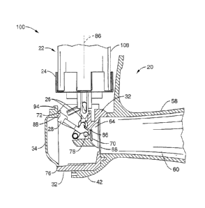
Referring first to FIGS. lA and 1B, an inhaler 20 of the present invention is
shown in an exploded view with a breath actuation assembly 100 and a dose
counter
assembly 130. The breath actuation assembly 100 and the dose counter assembly
130
are housed along with medicament fluid source 22 inside front cover 42, back
cover 44,
and top cap 54, all preferably comprising medical grade plastic or other
suitable
materials known in the art. Fluid source 22 may comprise a conventional
Metered Dose
Inhaler (MDI) container comprising a mixture of two or more active medicaments
in a
propellant. Fluid source 22 generally comprises container 108 holding the
mixture of
medicaments and propellant, and nozzle 110, which is in line with the
discharge axis 86
of the container 108, as shown in FIG. 6B. When the container 108 is advanced
relative
CA 02734135 2011-02-14
WO 2010/007361
PCT/GB2009/001740
- 11 -
to the nozzle 110 in the direction of the discharge axis 86 (i.e. the nozzle
110 is pushed
into the container 108), the medicament is discharged out the nozzle 110 in
the direction
of the discharge axis 86.
Turning now to FIGS. 2A through 2C, inhaler 20 is shown in an assembled
configuration with dust cover 40 pivotally mounted to cover inhalation horn
58. The
dust cover 40 may be rotated away from horn 58 to expose opening 60, as shown
in
FIG. 2B. A manual release button 62, as shown in FIG. 2C, may also be
incorporated
into the back cover 44. Top cap 54 has an opening 56 to give visual access to
display
wheel 52.
Referring also to FIGS. 1B and 3A through 3E, the breath actuation assembly
100 comprises a housing or transducer 32 that rotatably houses lower link 28
at pivot
78. Lower link 28 is connected to upper link 26 at collapsible joint 66.
Reference may
also be made to FIGS. 5A-6B, wherein the transducer is illustrated in greater
detail.
Container holder 24 is shaped to receive the nozzle end of container 108 such
that the
nozzle 110 passes through to contact surface 112 of the transducer 32.
Container holder
24 also has a pair of guides 122 having slots 90 sized to house a pair of
bosses 92 as
shown in FIG 7A at the upper end of upper link 26.
As shown in FIGS. 3A through 4B, flap 34 is rotatably mounted to the
transducer 32 via peg 98, which extends across the top surface of flap 34, and
holes 114
in the sidewalls of transducer 32. The bottom and side extremities of flap 34
are sized to
fit within the internal surface of transducer 32 to form gap 76. The flap 34
has an upper
restraining surface 72 configured to retain arm 74 of lower link 28 when the
flap is in its
nominal position shown in FIG. 4B.
As illustrated in FIGS. 6A and 6B, the transducer 32 is configured to receive
nozzle 110 of fluid source 22 at surface 112. The transducer also comprises an
inlet 106
that spans from surface 112 to a first chamber 102. The inlet 106 is
configured to be in
line with the nozzle 110 and discharge axis 86 such that medicament discharged
from
the fluid source 22 is received through the inlet 106 and downstream into
first chamber
102.
The transducer 32 is also configured to receive plug 38 having bluff surface
104.
Fluid entering chamber 102 through inlet 106 is dispersed and redirected by
plug 38 and
CA 02734135 2015-12-30
- 12 -
into outlet 124 that terminates downstream at section 68 of second chamber 64.
The
fluid dispersion characteristics of transducer 32 can be seen in greater
detail with
reference to U.S. Patent 4,972,830 and EP308524B.
The fluid source 22 is biased to discharge along axis 86 by compressing a
loading member, such as biasing spring 48, between the top cap 54 and
container
sleeve 46, which is adapted to receive the other end of the container 108
opposite the
nozzle 110. Biasing spring 48 preloads the container 108 to move in the
direction of
surface 112 of transducer 32 along the discharge axis 86.
In the stowed configuration shown in FIG. 3 A, the fluid source container 108
is retained from translating along axis 86 by a collapsible linkage comprising
upper
link 26 and lower link 28. Upper link 26 and lower link 28 are rotatably
coupled at a
collapsible knee-type joint 66. The upper end of upper link 26 has a pair of
bosses 92
that are retained by a pair of guides 122 in the container holder 24 having
slots 90.
The guides are generally in-line, or at least parallel with the discharge axis
86, and
allow motion of the bosses 92 (see FIG. 7A) of the upper link to slideably
translate
upward and downward in the discharge axis 86, as well as allow the boss to
rotate as
necessary. The lower link 28 has one end fixed to the transducer 32 at pivot
78. As
illustrated in FIG. 3A, the boss 92 of the upper link 26 and pivot 78 of the
lower link
are essentially in-line with discharge axis 86, i.e. they form a loading path
that is
parallel to, or aligned with the discharge axis 86. Because collapsible joint
66 is off-
centre, i.e. positioned away from the loading path formed by the boss 92 of
the upper
link 26 and pivot 78, the downward force imposed by biasing spring 48 on the
container 108 in the stowed position predisposes the knee joint 66 to
collapse. Such
collapse is restrained in the stowed position by imposition of arm 74 of lower
link 28
on flap 34.
FIG. 3B illustrates the initiation of the breath actuation mechanism 100
caused
by inhalation by a patient through the opening 60 of horn 58. As shown in
FIGS. 3B-
3C and 4A, an outward airflow 80 is created in the second chamber 64, which
pulls
through a plurality of slots 70 in the transducer. Suction of air through
slots 70 creates
a small pressure differential 82 across the inner surface of flap 34, causing
the flap to
rotate about peg 98 and into the cavity of the transducer 32, as illustrated
in FIGS. 3A
and 3B.
CA 02734135 2015-12-30
- 13 -
The gap 76 between the flap 34 and the transducer 32 provides enough clearance
to
allow the flap to rotate into the cavity of the transducer, while also being
small
enough to allow a pressure differential with minimal suction on the horn. As
the flap
34 rotates, arm 74 of the lower link 28 is no longer retained by the upper
surface 72 of
the flap, and the arm 74 clears the flap 34 through recess 88 as the lower
link 28 is
allowed to rotate about pivot 78.
With rotation of the lower link 28 as shown in FIG. 3C, the collapsible joint
66 moves over centre, allowing the container holder 24 and container 108 to
translate
downward along axis 86, forcing a portion of the nozzle 110 into the container
108 to
stimulate discharge of the medicament from the container 108. The medicament
travels through the first chamber 102 and into the second chamber 64 where it
is
entrained with air flowing through slots 70, as described in further detail in
U.S.
Patent 4,972,830. In the embodiment shown, the second chamber 64 has an
internal
cross section that is shaped like a parabola. The entrained medicament flows
through
the second chamber 64 and out of the opening 60 of horn 58 to be inhaled by
the
patient. Therefore, the release of the metered dose of medicament is timed to
be
inhaled by the patient at an optimal moment during the inhalation phase of the
patient's breath cycle.
After the inhalation of the dose by the patient, the flap is returned to its
nominal position shown in FIG. 3D by a return force exerted by flap spring 36.
Flap
spring 36 is a metallic rod or wire assembled between retention arms 96 of the
transducer 32 and flange 94 on the flap 34. Rotation of the flap bends the
spring to
create a return force to return the flap 94 to its nominal position after the
inhalation
forces have subsided.
The upper and lower links 26, 28, container holder 24, and container 108
remain in the collapsed discharge position as seen in FIG. 3D due to the force
imposed by the biasing spring 48. The return of the dust cover 40 (described
in greater
detail with reference to FIGS. 7A-7E below) to cover the horn 58 manually
forces the
container holder 24 and container 108 to return to the stowed position under
compression from biasing spring 48. Return torsion spring 30 is mounted on
lower
link 28 to engage the transducer 32 such that a torsional force is exerted on
the
collapsible linkage to return to
CA 02734135 2011-02-14
WO 2010/007361
PCT/GB2009/001740
-14-
the locked configuration. The collapsible joint 66 is thus retained from
collapsing once
the dust cover 40 is again opened.
Turning to FIGS. 7A-7E, the operation of the dust cover 40 will now be
described. In the present embodiment, the dust cover 40 not only serves as a
shield to
cover horn entrance 60, but it also serves to reset the container to the
stowed position
after discharge of the medicament. FIG. 7A illustrates inhaler 20 in a stowed
configuration with the dust cover 40 shielding the entrance 60 to horn 58. The
dust
cover 40 is pivotably connected to the transducer 32 such that it can be
rotated out of
place to allow access to the horn opening 60. In alternative embodiments, the
dust cover
may be pivotably connected to either the front or back covers 42, 44. The dust
cover 40
has two cams 120, which are configured to engage the bottom surface of guides
122 of
container holder 24 through its entire range of motion along axis 86. When the
dust
cover 40 is rotated about pivot 118 (shown in FIG. 7B), the cams disengage
guides 122.
The container holder 24 and container 108 remain in the stowed position from
the over-
centre orientation of the collapsible linkage.
FIG. 7C illustrates the breath actuation assembly 100 in the collapsed
configuration with the container holder 24 and container 108 in the discharge
position.
The breath actuation assembly 100 is biased to remain in this configuration
due to the
compressive force of the biasing spring 48. When the dust cover is rotated
back toward
the horn opening 60, as shown in FIG. 7D, the cams 120 engage the bottom
surface of
guide 122, pushing' the container holder 24 and container 108 upward along
axis 86.
When the dust cover 40 is in its final stowed position covering the horn
entrance 60, the
cams 120 have pushed the container holder 24 to the stowed position, as shown
in
FIG. 7A. In this configuration, the return spring 30 has reset the breath
actuation
assembly 100 to the locked position, and movement of the container 108 will be
retained by the dust cover cams independent of the collapsible linkage.
The inhaler 20 preferably includes a dose counter for automatically counting
the
remaining doses left in the container after each discharge of the medicament.
The
inhaler may be configured with a dose counter having a number of different
configurations, including mechanical or electrical counters. The operation of
a preferred
CA 02734135 2011-02-14
WO 2010/007361
PCT/GB2009/001740
-15-
embodiment utilizing a mechanical dose counter assembly 130 will be described
with
respect to FIGS. 8A to 12E.
FIG. 8A illustrates inhaler 20 with dose counter assembly 130 configured above
the container sleeve 46. The container sleeve 46 is sized to receive the non-
dispensing
end of the container 108. The container sleeve preferably has one or more tabs
132
having a boss 136 configured to engage the teeth of first wheel 50 disposed
just above
the container sleeve 46. The embodiment shown in FIG. 9 has two tabs 132 and
bosses
136. However, it will be appreciated that any number of tabs and bosses may be
employed.
Referring back to FIG. 8A, first wheel 50 is a gear rotatably mounted in a
horizontal orientation to top cap 54. Wheel 50 has a plurality of lower teeth
140 and
upper teeth 138 disposed along the outer perimeter of wheel 50.
In a preferred embodiment, display wheel 52 is also rotatably mounted to top
cap
54 in a horizontal orientation between first wheel 50 and the top cap. Display
wheel 52
has an opening 154 to allow clearance for column 142 of first wheel 50 that is
vertically
disposed to mount to top cap 54. Display wheel 52 has markings 150 to indicate
the
number of doses left in the container 108 based on the position of the display
wheel 52.
As seen in FIG. 2A and 2B, the markings 150 that are showing through opening
56 in
top cap 54 indicate the number of remaining doses.
FIGS. 8A-8D illustrate the interaction between the container sleeve 46 and the
first wheel 50 upon discharge of the fluid source 22. When the container 108
is in the
stowed position, boss 136 lines up on the perimeter of wheel 50 between two of
the
upper teeth 138. As the container 108 and container sleeve 46 moves downward
along
the discharge axis as a result of the breath actuation mechanism, boss 136
Contacts the
upper incline of one of the lower teeth 140, as shown in FIG. 8B. The boss 136
continues its translation along axis 86, forcing the first wheel 50 to turn
clockwise
(looking down from the top) until the container 108 reaches the discharge
position, as
shown in FIG. 8C. When the dust cover 40 is closed to return the container 108
to the
stowed position, boss 136 translates upward until contacting the lower incline
of upper
tooth 138, as shown in FIG. 8D. The boss 136 continues its upward translation,
forcing
CA 02734135 2015-12-30
- 16 -
the wheel 50 to further turn clockwise until the container 108 reaches the
stowed
position, shown in FIG. 8A. When another dose is dispensed, the cycle repeats.
The lower wheel 50 may be configured to vary the number of doses required
to turn the lower wheel 360 degrees by varying the number of teeth. In the
above
embodiment, a 40-tooth index was used. However, this number may be varied
depending on the number of doses included in the container.
FIGS. 12A-12C illustrate the interaction between the display wheel 52 and the
lower wheel 50. As shown in Figure 10 and in hidden line in FIGS 12A-12C, the
lower wheel 50 has a drive peg 144 disposed on the upper surface of the lower
wheel.
Display wheel 52 has a plurality of semi-circular receiving pegs 152 disposed
on the
lower surface of the display wheel. As first wheel rotates about column mount
142,
drive peg 144 engages a first of the receiving pegs 152 and causes the display
wheel
52 to rotate about mount 156 a specified distance along mark 150, the
specified
distance indicating the range of doses left (e.g. "full 200 to 160") (see FIG.
I2A). At a
portion of first wheel's rotation, the drive peg 144 slips past the first of
the receiving
pegs 152 (see FIG. 12B) and continues to complete one full rotation (40 doses)
until
contacting the second of the receiving pegs 152 (FIG. 12C). The cycle repeats
itself
until all the receiving pegs 152 are driven such that the "empty" indicator is
displayed
at window 56 when the specified number of doses has been dispensed.
The effect of the gearing as shown in FIGS. 12A-C is to scale the motion of
the display wheel 52 with respect to the first wheel 50. To change the scale
of the
motion, one or more additional driving pegs 144 may be disposed on the upper
surface of the first wheel 50. For example, a second driving peg (not shown)
may be
disposed 180 degrees from the first such that the display wheel would advance
twice
as fast relative to the first wheel for a container having 100 total doses.
FIG. 13 illustrates an alternative embodiment showing an inhaler having a
breath actuated release mechanism 200 using a diaphragm 202 rather than the
flap 34
shown in FIGS. 1-7E. The diaphragm 202 is configured to mount to transducer
204
and be sized so that a portion of the diaphragm deflects in response to
inhalation
forces from the patient. Release mechanism 200 further includes a catch 214
coupled
to the diaphragm
CA 02734135 2015-12-30
- 17 -
and the lower link 208 to retain the collapsible linkage comprised of the
lower link
208 arid the upper link 210.
During use, inhalation forces from the patient deflect the portion of the
diaphragm in communication with catch 214. Motion of the catch 214 allows
lower
link 208 to rotate past the catch, thereby allowing the 208/210 linkage to
collapse and
discharge fluid source 22.
FIGS. 14-17 illustrate another alternative embodiment of inhaler 300 having a
load lever 302 and a breath actuated release mechanism 350 on top of fluid
source 22.
By placing the release mechanism above the MDI container, the mechanism can be
applied to any MD1 actuator with minimal mold modification. Inhaler 300 has a
lower
portion 304 housing fluid source 22 and a transducer (not shown) for
dispersing the
medicament. Middle body 308 interfaces with lower portion 304 and slideably
houses
plunger 318 to selectively advance fluid source 22 downward to discharge the
medicament.
Plunger 318 is retained from moving relative to middle body 308 by a
collapsible linkage comprising lower link 320 and upper link 322. Plunger 308
is also
configured to receive biasing spring 312 at its up extremity. The biasing
spring 312 is
shaped to receive spring cap 310 which may be depressed to compress spring 312
against plunger 318 in a downward discharge direction, as shown in FIG. 16 A.
To
depress spring cap 310, load lever 302 is rotatably attached to top shell 306
such that
rotation of load lever 302 to a vertical orientation forces the spring cap 310
down to
bias the plunger to discharge fluid source 22.
Motion of the collapsible link 320, and linkage 320/322, is restrained by flap
316. Flap 316 is pivotably mounted such that inhalation forces cause it to
rotate as
illustrated in FIG. 16B, thereby allowing the lower link 320 to rotate
downward such
that linkage 320/322 collapses. The biasing force from spring 312 forces the
plunger
downward as illustrated in FIG. 16C. The load lever 302 is then reset to the
first
position, allowing the fluid source 22 to translate back to the stowed
position
illustrated in FIG. 160.
FIG. 17 illustrates an embodiment of the inhaler 300 incorporating an
electronic dose counter 324. In such a configuration, flap 316 is coupled to
trigger
326, which
CA 02734135 2011-02-14
WO 2010/007361 PCT/GB2009/001740
-18-
depresses a sensor in dose counter 324 each time the flap is tripped to
dispense a dose
of medicament. Dose counter 324 generally comprises a printed circuit board
(PCB) and
other electronic components such as an LCD to digitally display the dose
count.
Alternatively, a mechanical dose counter may instead be incorporated into
inhaler 300
in much the same way as the inhaler disclosed in FIGS. 9-12, or FIGS. 21A-23.
Figures 18 through 20B illustrate another alternative embodiment of the
present
invention with inhaler 400 having a mechanical dose counter 420 that has a
vertically
mounted display wheel 422. Inhaler 400 has a load lever 402 that manually
biases the
fluid source 22 discharge upon downward motion.
As illustrated in FIG. 19A, fluid source 22 is retained from discharging by ,
collapsible joint 416, which is formed by the junction of upper link 406 and
lower link
408. Lower link is coupled to horizontally oriented flap 410. Inhalation
forces on horn
404 cause air flow through port 412 into negative pressure chamber 414 such
that a
negative pressure is exerted on flap 410 to force flap 410 to rotate downward,
as shown
in FIG. 19B. With collapsible joint 416 away from the locked position, the
fluid source
is free to translate downward and discharge the medicament.
Figures 20A and 20B illustrate an alternative embodiment of using a dose
counter 420 with a vertically oriented display wheel 422. Container sleeve
426, adapted
to receive the non-dispensing end of container 22, has a plurality of
protrusions 434.
When the container cycles- downward upon discharge, translation of the
container sleeve
426 causes protrusions 434 to strike the teeth 432 of gear 424, forcing the
gear 424 to
rotate clockwise. The clockwise rotation of gear 424 engages vertically
oriented
sprocket 430 of display wheel 422, causing the display wheel 422 to turn.
Sprocket 430
may be configured to engage gear 424 at specified intervals to vary the rate
of rotation
of the display wheel 422 with respect to the rate of rotation of the gear 424.
Referring to FIG. 21A-F, another preferred embodiment is shown as dose
counter mechanism 450. The mechanism 450 comprises a canister sleeve 46 which
is
rotationally constrained, but able to move axially with an MDI canister, and a
rotatable
top link 452. The top link 452 is coupled to gear column 468 such that gear
column 468
rotates incrementally with rotation of the top link. In FIG. 21A, the
mechanism 450 is in
ready state (prior to breath actuation) with the canister sleeve 46 in the
upward-most
CA 02734135 2011-02-14
WO 2010/007361
PCT/GB2009/001740
-19-
position in its travel. The canister sleeve 46 has a plurality of teeth 456
that are shaped
to mate with and lock with the teeth 454 of the top link 452. In other words,
both teeth
456 and 454 have opposing angled surfaces that prevent rotation of the top
link 452
with respect to the canister sleeve 46 when engaged. When MDI canister 22
(shown in
FIG. 1B) is actuated, the canister sleeve 46 and top link 452 move downward.
A compression load is generated on the top link. 452 from count spring 462,
which is disposed between the display wheel 464 and top link 452. The count
spring
keeps the top link 452 and canister sleeve 46 together, ensuring engagement of
the teeth
456, 454. Any other suitable resilient biasing means such as a compressible
rubber
element could also be used. The top link has a plurality of radial
protrusions, or keys
460 around its periphery which are positioned and sized to mate with the
columnar tines
458 of cap bottom 466. Cap bottom 466 may be bonded to or integral with top
cap 470
(shown in FIG. 22) or a cover piece, such that the tines 458 remain fixed
during motion
of the canister and the top link 452. As the canister sleeve 46 and the top
link move
down the opposing inclined surfaces of the key 460 and cap bottom 466 engage,
causing
the top link 452 to separate from the canister sleeve 46 and allowing the
teeth 456, 454
to partially disengage and slide past each other. The top link 452 therefore
becomes able
to rotate relative to the canister sleeve 46. The opposing angled surfaces of
the key 460
and the tines 458 can now slide past one another, causing the top link to
rotate 4.50 as
seen in FIG 21B.
Referring now to FIG. 21C, the canister sleeve 46 continues to travel downward
without further rotation, as the keys 460 of the top link push in between the
columnar
tines 458 of the cap bottom 466. When the canister sleeve 46 has bottomed out,
as
shown in FIG. 21D, it will then rebound and then start moving up towards its
original
'ready state positioning, pushing the top link 452 up with it. At this stage
the points of
the teeth 454 of the top link have passed beyond the points of the teeth 456
of the
canister sleeve 46. Further rotation of the top link 452 is prevented by the
engagement
of the key 460 and the tines 458. As the canister sleeve 46 moves up further,
the key
460 clears the tines 458 of the cap bottom 466 as shown in FIG. 21E. The teeth
456 of
the canister sleeve 46 then fully re-engage the teeth 454 of the top link 452,
causing the
top link 452 to rotate another 4.5 clockwise, as shown in FIG.21F. This
completes the
CA 02734135 2011-02-14
WO 2010/007361
PCT/GB2009/001740
-20-
full cycle of MDI canister actuation and the indexing mechanism has rotated a
total of
9 . The indexing mechanism top link 452 has advanced 1/40th of a full
revolution per
actuation.
Referring now to FIG. 22A, the dose counter mechanism 450 is mounted on top
of the breath actuation assembly 100 (see FIG. 1B). Top cap 470 surrounds
canister
sleeve 46, shown in FIG. 22B with a section of the top cap 470 removed for
clarity. The
top cap has a window 472 for showing the dose count as provided by the display
wheel
464. Display wheel 464 has a display label 474 showing remaining dose counts
from 0
to 200 in ten dose increments (e.g. markings of 200, 190, 180, etc).
FIG. 23 illustrates a top portion of the top cap 470 cut out and display label
474
removed to show planetary gear mechanism 478. The display wheel 464 is
rotationally
coupled to gear column 468 via three intermediary gears 476. The three
intermediary
gears 476 of the planetary gear mechanism 478 are driven by the rotation of
centre gear
column 468. The teeth of the three intermediary gears 476 mate with the
internal geared
surface of the top cap 470 such that the display wheel 464 rotates clockwise.
When the
centre gear column 468 rotates 90 due to motion of the indexing mechanism, the
planetary gear will rotate the display wheel 1/10 of a graduation. The label
is set to a
resolution of 10 shots per indication, however may be altered to reflect
different
increments. After 200 actuations, the label will have advanced total of 260 -
going
from "200" to "0" or "Empty".
The planetary gear mechanism 478 has the effect of scaling down the rotational
motion of the top link 452 and gear column so that the display wheel may
rotate through
200 actuations in less than one full rotation. For smaller dose counts (e.g.
120 or 60
count canisters), the display wheel may simply be positioned so that the
correct count is
initially viewed through window 472. Alternatively, a different tooth count
for the
planetary gear mechanism 478 may be implemented along with changing the
display
label 474 to accommodate different total dose counts.
Referring to FIG 24A-D, the breath actuation mechanism 500 is another
preferred embodiment that incorporates a trip link 502 to increase the
operational range
of previously described breath actuation mechanism 100 shown in FIGS. '3A
through
4E.
CA 02734135 2011-02-14
WO 2010/007361
PCT/GB2009/001740
-21-
FIG. 24 illustrates the breath actuation mechanism is ready (non actuated, and
loaded) stated. Instead of interfacing directly with flap 34, lower link 504
interfaces
indirectly with flap 34 via trip link 502. The upper link 506 and lower link
504 retain
motion of the fluid source 22 and load F from biasing spring via locking knee
joint 66.
Knee joint 66 is located off-centre from load F in discharge axis 86 (i.e. the
discharge
axis 86 passes through pivot 78 and the boss of 516 of upper link 506 through
FIGS.
24A-D), thus the downward force imposed by biasing spring 48 on the container
108 in
the ready position predisposes the knee joint 66 to collapse.
The upper link 506 and lower link 504 are restrained from rotating or
collapsing
because the lower link 504 is locked from rotation from a catch, or trip edge
510 in trip
link 502. Trip link 502 is locked from rotating because of impingement of
upper
surfaces (contact surface) 512 of the trip link 502 with a restraining
surface, or circular
cutout 514, in flap 508.
Referring now to FIG. 24B, when flap 508 rotates due to force created by
patent
inhalation (vacuum), upper edge 512 if the trip link clears the cutout 514,
allowing the
trip link 502 to rotate clockwise. Trip edge 510 corresponding rotates to
release the
contacting surface of the lower link 504.
With lower link 504 now unrestrained, as shown in FIG. 24C, knee joint 66
collapses and shifts to the left. Because of constraints on the top edges of
upper link 506
with container holder 24, the upper link can only travel in line with the
force load path
F, and trip link 502 further rotates clockwise, causing lower link 504 to
further rotate
counter-clockwise.
Referring now to FIG. 24D, the mechanism further collapses as lower link 504
continues to rotate counter-clockwise on joint 78, 26 travels down allowing
MDI
canister 22 to travel downward causing the valve stem to activate.
After activation, the canister travels upwards such that the knee joint moves
back
towards its stowed orientation with lower link rotating clockwise towards trip
link 502.
The trip link 502 is able to catch lower link 504 in trip edge 510 for
retention of the
knee joint 66 until subsequent breath actuation of flap 508.
CA 02734135 2011-02-14
WO 2010/007361
PCT/GB2009/001740
-22-
The addition of trip link 502 over previously described embodiments expands
the
operational margin of the lower 504 with the flap 508, improving overlap on
trip edges
to ease manufacturing tolerances while maintaining breath actuation
sensitivity.
In particular, the addition of the trip link 502 expands the operational
margin of
the lower link 504 with the flap 508 in that, when in the ready state, the
inhaler is less
prone to accidental actuation as a result of a sudden movement or vibration of
the
inhaler which causes an unintended rotation of the flap 508. With reference to
FIG.
24A, it will be seen that the amount of overlap between the cutout surface 514
and the
meeting upper edge 512 is sufficient for the flap 508 be able to rotate a
considerable
distance without the trip link 502 'being released so as to allow the knee
joint 66 to
collapse. Since the mating surfaces 514, 512 have a cylindrical shape with a
concentric
curvature, the area of contact between the flap 508 and trip link 502 remains
comparatively large until just before the trip link 502 is released. This also
contributes
to rendering it more difficult to accidentally actuate the inhaler.
Furthermore, after actuation, the canister travels upward and the lower link
504
engages the trip link 502. An end 520 of the lower link 504 engages a portion
522 of the
trip link 502 and pushes the trip link 502 so as to rotate said link 502 in an
anti-
clockwise direction (FIG. 24D). As the trip link 502 so rotates, the flap 508
may be
cammed along a surface 524 of the trip link 502. The surface 524 is configured
relative
to the rotational axis of the trip link 502 so as to engage with the flap 508
in such a way
that rotation of the trip link 502 is not prevented by the engagement
therewith of the
flap 508. The arrangement of the trip link surface 524 may be such said
surface is
cylindrical with a centre of curvature coincident with the rotational axis of
the trip link
502. In this way, as the trip link 502 rotates in an anti-clockwise direction
(as viewed in
FIG. 24), the engagement between the flap 508 and trip link surface 524 is
such that the
flap 508 is not itself rotated. However, the surface 524 may be arranged so
that, as the
trip link 502 rotates in an anti-clockwise direction, the surface 524 allows a
camming of
the flap 508 back towards a ready state position. It will be understood
therefore that the
surface 524 facilitates a return of the linkage and flap 508 back to the ready
state
position and ensures a movement of the linkage back to this position is not
prevented by
CA 02734135 2011-02-14
WO 2010/007361
PCT/GB2009/001740
-23-
the flap 508. In the arrangement shown in FIG.24, the surface 524 is arranged
on the
trip link 502 adjacent the upper edge 512.
As the lower link 504 pushes the trip link 502 in the anti-clockwise
direction, the
end 520 of the lower link 504 cams into a groove 526 partly defined by trip
edge 510.
Although the description above contains many details, these should not be
construed as limiting the scope of the invention but as merely providing
illustrations of
some of the presently preferred embodiments of this invention.
=
=