Note: Descriptions are shown in the official language in which they were submitted.
CA 02734424 2011-03-18
METHOD AND APPARATUS FOR INVESTIGATING MECHANICAL PROPERTIES
OF SOFT MATERIALS
Field of Invention
[0001] The invention relates to the field of probes for measuring the
tensional
strength or stress/strain character of materials that can be pierced such as
sediment,
soil, snow, food stuffs and/or other soft materials.
Background of Invention
[0002] It is often desired to measure the tensional strength or stress in a
pierce-
able material such as in sediment or soil. (Note that the term "tension" is
utilized herein
in the engineering sense of a stress that pulls on both ends of a member and
not in the
sense of the tenacity with which soil particles hold to water. )
[0003] The strength of soil, snow, sediment and other soft materials is a
measure
of the capacity of the material to resist deformation and can be understood in
terms of
the amount of energy required to break apart pieces of the material or move
implements
through the material or a measure of the amount of weight a given area of the
material
will support. Material failure may be in the form of. permanent deformation
through
externally applied stress, e.g., sinking of a structure into the soil, breakup
of the soil
surface as in plowing; or alternatively failure may be from stresses affecting
an unstable
slope as in avalanches, mudslides, or erosion.
[0004] Soil strength tests are well established and described in multiple
standard
tests such as ASTM D1 194 (load plates), D1586 (standard penetration test),
D3441
(cone penetration test), D4429 (bearing ratio in place) and ASAE S313.2 (soil
cone
penetrometer). All of these tests pertain to measurements made by compressing
the
test material. Similarly, testing of soils using a flat plate dilatometer for
determining
stress/ strain characteristics (ASTM 6635-01) is also done using compression.
A less
common test for measuring the strength of soil determines shear strength as
covered in
-1-
CA 02734424 2011-03-18
ASTM D2573 - 08, Standard Test Method for Field Vane Shear Test in Cohesive
Soil,
or additionally ASTM STP 1014.
[0005] While measurements of compression and shear of soil, sediment, snow,
food stuffs and other such pierce-able materials give important information
about
strength, there is additional information in measurements made with the sample
in
tension. In particular, the strength of materials in engineering studies is
known to show
differences depending on whether the test sample is subjected to compression
or
tension. For example, fibre reinforced materials typically show greater
strengths in
tension than in compression, and fibrous materials in soils and sediment are
common.
In addition, where a material contains defects, e.g., small cracks, tension
can result in
failure by fracture, whereas, compression may force small defects to close and
not act
as loci of failure.
[0006] Many studies of the strength of soil, snow, sediment, food stuffs and
other
such pierce-able materials have shown the importance of fracture as a
mechanism of
failure, e.g., failure of sediments during methane bubble growth and rise (see
from
reference list below Johnson et al., 2002; Boudreau et al., 2005); failure of
sediments
during animal locomotion (Dorgan, et al. (2005) and Jumars et al. (2007));
failure of
soils (e.g., Wang, et al., 2007; Hallet and Newson, 2001); failure of snow
(e.g.,
McClung, 2007); failure of foodstuff (e.g., Scanlon and Long, 1995) . However,
probes
for measuring the strength of soil, snow, sediment, foodstuffs and other such
pierce-
able material have measured compression or shear strength, and laboratory
measurements have typically relied on engineering type sample compression or
tension
loading or three point bending or cantilever tests. In our understanding,
there are at
present no in situ probes for measuring failure of soil, snow, sediment,
foodstuff and
other such pierce-able materials in tension.
[0007] In situ probe measurements can provide information on material strength
at small intervals of distance, whereas typical engineering measurements on
samples in
tension or compression cause the sample to fail only at its weakest point
which provides
only a single datum for that sample. While in situ probes offer advantages in
resolution
-2-
CA 02734424 2011-03-18
of material strength over distance, current in situ probes typically measure
compression
or shear failure. This is a problem because the strength of sediment, soil,
snow,
foodstuff or other such pierce-able materials in tension is important for
identifying
discontinuities or other regions of weakness that may result in slumping or
failure as in
mud slides and avalanches or may indicate regions of weakness that may result
in
erosion or other modes of failure. Measurement of materials in tension is
superior to
measurement in compression for identifying dislocations, defects, and weak
layers
since compression presses surfaces together rather than pulling them apart.
[0008] Further, measurements of failure in tension provide different
information
than failure in shear because shear strength can be enhanced through
interlocking of
grains of sand or gravel, or granular snow or ice. Shear may actually close
defects that
tension will open and cause material failure. For example, measurements of
compression and shear failure on clean sand show a much greater strength than
measurements of tension on the same material. The difficulty of interpreting
measurements from a compressive type probe are apparent in use of the cone
penetrometer, a type of probe often used to determine strength of soil and
sediments.
This device uses a cone shaped probe head that is driven into the soil either
at constant
speed or with constant force and the resistance to penetration is measured
with a force
sensor. Considerable effort has gone into improving this method by adding
sensors to
measure friction force and pore water pressure. Still, difficulty in
interpreting cone
penetrometer measurements in terms of type of material, e.g., sand, silt,
gravel, etc.,
requires typically that samples of the material be collected and assessed.
[0009] In determining the strength of snow to assess the risk of avalanches
methods are often simple and effective, but do not provide information on
material
strength other than failure under the conditions of the test. This means that
while a
particular test may show the snow to be safe, there is not sufficient
information to
determine if small changes in conditions, e.g., moisture content, temperature,
etc.,
might make the snow pack prone to failure. Commonly used methods for measuring
stability of snow against avalanches typically involve digging snow pits and
then
determining the stability when applying stress at the surface. One example is
the
-3-
CA 02734424 2011-03-18
stuffblock test (Birkeland, K.W., R.F. Johnson and D. Herzberg. 1996). In this
test a bag
filled with 10 lbs of snow is dropped from various heights onto a column of
snow at the
edge of a snow pit. In application of this method the snow fails typically at
a single
point, whereas, measurements with an in situ probe that measures failure under
tension
could provide measurements of material strength over small depth intervals and
thereby
identify regions that may be near failure and that may fail if the conditions
change.
[00010] Force measurements in food assessments typically involve: puncture,
compression-extrusion, cutting-shear, compression, tension, torsion, bending
and
snapping and deformation. Tension measurements are typically done with samples
of
specific dimensions subjected to typical engineering testing to determine
elongation and
failure. Probes used for assessing foods are typically for measurement of
puncture
strength, moisture or thermal properties.
[00011] Mitsuru Taniwaki, et al., developed a method for assessing food
texture in
which a probe is inserted into a food sample and the vibration caused by the
sample's
fracture is detected using a piezoelectric sensor. The method follows previous
work in
which the sounds of food mastication were recorded. Results show promise for
assessing food texture, but have not proven useful for quantifying fracture
strength.
[00012] A variety of probes are disclosed in the patent literature. U.S.
Patent No.
4,806,153 discloses a penetrometer for soils that uses sensors to measure
compressive
resistance to penetration, friction from penetration and pore water pressure.
U.S.
Patent No. 5,831,161 discloses a penetrometer for snow that measures
compressive
resistance to penetration using a force transducer. U.S. Patent No.7,040,146
discloses
a soil and snow penetrometer that uses sensors to measure the compressive
resistance
to penetration of a probe head into soil and snow. It uses a load cell and
accelerometer
and a processor to interpret results in terms of the compressive vertical
strength of soil
or snow. U.S. Patent Nos. 4,061,021, 5,726,349, 5,663,649 also describe probes
that
measure compressive strength of soils and other soft materials.
[00013] In addition, probes have been described for measuring shear strength
and
Young's modulus of soils, snow and sediments, including U.S. Patent No.
4,594,899
-4-
CA 02734424 2011-03-18
which describes a probe for soil that is comprised of two concentric
cylinders. When
inserted into the soil, the rotary response of the inner cylinder is measured
in response
to a known rotary excitation and is interpreted in terms of the soil
liquefaction resistance
and soil degradation.
[00014] Despite the considerable art in the field, a need still exists for an
in situ
method and apparatus for measuring the tensional strength of soil, snow,
sediment,
foodstuff and other such pierce-able materials.
[00015] References Cited:
A. Birkeland, K.W., R.F. Johnson and D. Herzberg. (1996) The stuff block snow
stability test. Technical Report 9623-2836-MTDC. U.S. Department of
Agriculture Forest Service, Missoula Technology and Development Center,
Missoula, Montana, 20 pp.
B. Boudreau, B.P., Algar, C., Johnson. B.D., Croudace, I., Reed, A., Furukawa,
Y.,
Dorgan, K.M., Jumars, P.A., Grader, A.S. & Gardiner, B.S. (2005). Bubble
growth and rise in sediments. Geology 33, 517-520.
C. Dorgan, K.M., Jumars, P.A., Johnson, B.D., Boudreau, B.P. & Landis, E.
(2005).
Burrow extension by crack propagation. Nature 433, 475.
D. Hallett, P.D. & Newson, T.A. (2001). A simple fracture mechanics approach
for
assessing ductile crack growth in soil. Soil Science Society America J. 65,
1083-
1088.
E. Johnson, B.D., Boudreau, B.P., Gardiner, B. & Maass, R. (2002). Mechanical
response of sediments to bubble growth. Mar. Geol. 187, 347-363.
F. Jumars, P.A., Dorgan, K.M.,Mayer, L.M., Boudreau, B.P., & Johnson, B.D.
(2007).Material constraints on infaunal lifestyles: may the persistent and
strong
forces be with you. Chapter 29. In Trace Fossils: Concepts, Problems,
Prospects. Elsevier Press.
-5-
CA 02734424 2011-03-18
G. McClung, D.M. (2007). Fracture energy applicable to dry snow slab avalanche
release. Geophys. Res. Let., 34, L02503, 5 pages)
H. Taniwaki,M., T. Hanada and N. Sakurai (2006). Device for acoustic
measurement of food texture using a piezoelectric sensor. Food Research
International, Volume 39, Issue 10, December 2006, 1099-1105.
1. Wang, J.-J., Jhu, J.-G., Chiu, C.F. &. Jhang, H. (2007). Experimental study
on
fracture toughness and tensile strength of a clay. Engineering Geol. 94, 65-
75.
J. U.S. 4,061,021 Dec. 1977 Baldwin et al
K. U.S. 4,594,899 Jun. 1986 Henkeetal.
L. U.S. 4,806,153 Feb. 1989 Sakaietal.
M. U.S. 5,663,649 Sept. 1997 Toppetal.
N. U.S. 5,726,349 Mar. 1998 Palmertree et al.
0. U.S. 5,831,161 Nov. 1998 Johnson etal.
P. U.S. 7,040,146 May 2006 Mackenzie et al.
Summary of Invention
[00016] One aspect of the invention provides a method for determining the
tensile
strength of a material. The method includes the steps of: (a) provisioning a
probe
comprising a housing and a longitudinal member rotatable in the housing, where
the
longitudinal member terminates in a coil spring thread that is situated
external to the
housing; (b) positioning the coil spring thread at a first depth in the
material; (c) rotating
the longitudinal member so as to pull the coil spring thread into the material
and
generate a reactionary pull substantially in a columnar portion of the
material scored by
the coil spring thread, following which the terminating end of the coil spring
thread will
be pulled to a second depth; (d) measuring a strain on the longitudinal member
as the
-6-
CA 02734424 2011-03-18
coils spring head moves to the second depth; and (e) determining the strength
of the
material based on the measured strain.
[00017] The columnar portion of the material may fracture at the second depth.
In
this case, the fracture strength of the material may be determined based on
the
measured strain at the second depth, a difference between the first and second
depths,
and a diameter of the coil spring thread.
[00018] The coil spring thread is preferably configured such that the
reactionary
force generated by it is directed inwardly towards the columnar portion of the
material
surrounded by the coil spring thread. To achieve this, coil spring thread
preferably has
a generally rectangular cross-sectional profile including a top corner
proximate the
longitudinal member and a diametrically opposed bottom corner distal the
longitudinal
member, the coil spring thread being canted so that the top corner is closer
to a central
axis of the coil spring thread than the bottom corner.
[00019] In an extension of the method, the probe may be moved to successively
increase the first depth and steps (c) to (e) repeated. This enables a
discrete plot of the
tensile strength of the material relative to the depth of the material.
[00020] In an alternate extension of the method, the probe may be continuously
moved deeper into the material at a predetermined rate that is less than a
rate at which
new material is drawn into the coil spring thread as a consequence of
continuously
rotating the longitudinal member. In this manner, stress can be built on
successive
columnar samples of the material as the probe is advanced into the material.
Steps (d)
and (e) are repeated to thereby continuously plot the tensile strength of the
material
relative to the depth of the material.
[00021] In any extension of the method, as the probe creates a bore in the
material
and the fracturing of columnar material samples yields loose materials that
may affect
the fracture signal, the method preferably includes clearing such loose
material out of
the bore.
-7-
CA 02734424 2011-03-18
[00022] Another aspect of the invention provides a probe apparatus for
determining the tensile strength of a material. The apparatus includes a
housing; a
longitudinal member rotatably journaled in the housing, the longitudinal
member
defining a longitudinal axis; a coil spring thread, rigidly connected to the
longitudinal
member, and disposed external of the housing; a mechanism for rotating the
longitudinal member and coil spring thread, wherein, upon rotation of the
longitudinal
member and coil spring thread, the coil spring thread is pulled into the
material causing
a stress on the longitudinal member and generating a reactionary pull in the
material; a
strain gauge for measuring the stress on the longitudinal member relative to
the
housing; and a controller connected to the strain gauge for determining the
tensile
strength of the material based on the stress experienced by the longitudinal
member.
[00023] The controller preferably measures the stress experienced by the
longitudinal member when the material fractures due to the reactionary pull.
[00024] As discussed above, the coil spring thread is preferably configured
such
that the reactionary force generated by it is directed inwardly towards the
columnar
portion of the material surrounded by the coil spring thread. To achieve this,
coil spring
thread preferably has a generally rectangular cross-sectional profile
including a top
corner proximate the longitudinal member and a diametrically opposed bottom
corner
distal the longitudinal member, the coil spring thread being canted so that
the top corner
is closer to a central axis of the coil spring thread than the bottom corner
[00025] The coil spring thread may be helical and concentric with the
longitudinal
member. The helical coil spring thread may have at least two volutes, one
volute being
proximate to the longitudinal member and one volute being distal to the
longitudinal
member, the distal volute having a diameter larger than the proximate volute.
A
transition portion may continue the longitudinal member and connect it with
the
proximate volute of the coil spring thread.
[00026] The probe may also include a hollow shaft rotatably mounted to the
housing. The longitudinal member is disposed within the hollow shaft and the
coil
spring thread is disposed external of the hollow shaft. The hollow shaft
having an auger
-8-
CA 02734424 2011-03-18
blade connected to the outer wall of the shaft, the hollow shaft being rotated
by the
motor or an another motor. The auger is preferably provided for clearing loose
material
out of the bore created by the probe.
[00027] To move the probe downwardly, a moving stage may be mounted to
translate linearly within the housing and a motor provided for driving the
moving stage.
The hollow shaft and the longitudinal member depend from the moving stage, and
the
controller controls the rate of decent of the moving stage which, in turn will
control the
probe rate of decent. Preferably, the controller controls the linear
translation rate of the
moving stage and decent of the hollow shaft such that this rate is less than
the rate at
which new material is fed into the coil spring head, thereby enabling stress
to build up in
the column of material surrounded by the coil spring thread until the column
fractures.
[00028] Another aspect of the invention provides a method for determining the
tensile strength of a material. The method includes the steps of: (a)
provisioning a
probe comprising a housing having a longitudinal axis and a coil spring thread
that is
movably connected the housing rotationally and longitudinally; (b) rotating
the coil
spring thread such that said rotating drives the coil spring thread into the
material to
hold a volume of material therein, (c) generating a longitudinal force in the
coil spring
thread to urge the volume of material longitudinally away from remaining
material,
wherein the longitudinal force is resisted by adherence of the volume of
material to the
remaining material, (d) increasing the longitudinal force until the volume of
material
separates from the remaining material; and (e) determining the tensile
strength of the
material based on the longitudinal force applied in step (d) at the time the
volume of
material separated from the remaining material.
[00029] In one variant of this aspect of the invention, steps (b), (c) and (d)
occur
simultaneously. This may be accomplished, for instance, by rotating the
longitudinal
member in situ (where the vertical position of the longitudinal member is
fixed relative to
the housing), in which case, provided the coil spring thread has enough grip
in the
material, the rotation of the coil spring thread generates the longitudinal
force in the coil
spring and the reactionary force in the material, the longitudinal force
increasing as the
-9-
CA 02734424 2011-03-18
coil spring thread gets pulled deeper into the material until the volume of
material
separates from the remaining material. This may also be accomplished by
continuously
moving the longitudinal member and coil spring thread deeper into the material
at a
predetermined rate that is less than a rate at which new material is drawn
into the coil
spring thread as a consequence of it continuous rotation, in which case the
longitudinal
force increases as the coil spring thread gets moves deeper into the material
at a faster
rate than the rate of descent, until the volume of material separates from the
remaining
material.
[00030] In another variant of this aspect of the invention, step (b) may occur
separately than steps (c) and/or (d). This may be accomplished by first
rotating the
longitudinal member and coil spring member whilst enabling these components to
freely
move longitudinally into the material. Then, a longitudinal force is applied
to the
longitudinal member and the coil spring thread to urge the volume of material
longitudinally away from remaining material. The longitudinal force is then
increased
until the volume of material separates from the remaining material.
[00031] In another aspect, the invention is directed to a method for
determining the
tensile strength of a material, including:
(a) driving a material engagement head into the material to hold a volume of
material
therein, wherein the material engagement head has a longitudinal axis;
(b) generating a longitudinal force in the material engagement head to urge
the volume
of material longitudinally away from remaining material, wherein the
longitudinal force is
resisted by adherence of the volume of material to the remaining material;
(c) increasing the longitudinal force until the volume of material separates
from the
remaining material; and
(d) determining the tensile strength of the material based on the longitudinal
force
applied in step (c) at the time the volume of material separated from the
remaining
material.
-10-
CA 02734424 2011-03-18
[00032] In another aspect, the invention is directed to a probe for
determining the
tensile strength of a material, comprising a housing having a longitudinal
axis, a material
engagement head, disposed external of the housing and movable longitudinally
relative
to the housing, a motor system operatively connected to the material
engagement head
and operable to drive the material engagement head into the material, wherein
the
material engagement head is shaped to hold and engage a volume of material,
wherein
the motor system is further operable to exert a longitudinal force on the
material
engagement head, wherein the material engagement head is shaped to transmit
the
longitudinal force into the volume of material to urge the volume of material
longitudinally away from remaining material, wherein the motor system is
operable to
progressively increase the longitudinal force, a sensor positioned to sense
the
longitudinal force applied by the motor system, and a controller for receiving
signals
from the sensor, wherein the controller is programmed to determine the
longitudinal
force applied at the time that the volume of material separated from the
remaining
material.
Brief Description of the Drawings:
[00033] The foregoing and other advantages of the invention will be better
appreciated having regard to the following drawings, in which:
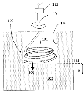
[00034] Figs. 1 and 2 are schematic representations of the subsurface testing
of
the tensile strength of a test material using a probe tip according to a
preferred
embodiment of the invention.
[00035] Fig. 3 is a cross-sectional and detail view of the probe tip assembly
shown
in Figs. 1 and 2.
[00036] Fig. 4 is a front view of an apparatus (with cover removed) for
rotating and
translating the probe tip.
[00037] Fig. 5 is a side view of the apparatus shown in Fig. 4.
-11-
CA 02734424 2011-03-18
[00038] Fig. 6 is a detail view of a low friction coupling employed in the
apparatus
shown in Fig. 4.
[00039] Fig. 7 is a detailed perspective view of a probe tip assembly used to
measure tensile strength in marine sediment beds.
Detailed Description of Preferred Embodiments
[00040] Figs. 1 and 2 are schematic views intended to illustrate the basic
operating
principles of a probe tip 100 for use with in situ testing of the strength of
a material 102.
The probe tip 100 is essentially a coil spring that functions as a thread so
as to be able
to screw into the material 102, and thus is referred to herein as a "coil
spring thread"
101.
[00041] In order to be able to quantify measurements, the coil spring thread
101
isolates a portion of the material 102 into a known geometric cross section.
This is
accomplished by the hollow nature of the coil spring thread 101, which, as it
scores into
the material, will surround a portion thereof. In the illustrated embodiment
the coil
spring thread 101 is helical so as to surround a cylindrical column 104 of the
material
102, and thus the known geometric cross section in the illustrated embodiment
will have
a diameter and depth.
[00042] In order to determine the tensile strength of the material, the probe
tip 100
must also function to apply a tensile stress to the isolated volume of the
material such
as cylindrical column 104. This accomplished by the cross-sectional profile of
the coil
spring thread 101, as will be discussed in greater detail below. It will be
seen that when
the coil spring thread 101 is rotated, the coil spring thread 101 will tend to
pull itself into
the material in a first longitudinal direction 106. In reaction, the material
will tend to pull
itself in an opposite longitudinal direction 108. (In other words, the coil
spring thread
101 generates a longitudinal force to urge the volume of material
longitudinally away
from remaining material, this longitudinal force being resisted by adherence
of the
volume of material to the remaining material.) In order to measure the
tension, the coil
-12-
CA 02734424 2011-03-18
spring thread 101 is rigidly connected to a longitudinal member 110 which,
while also
rotating, is held in place relative to a fixed or moving reference position
(the longitudinal
member 110 may rotate in situ or descent relatively slowly as discussed in
greater detail
below). Thus, as the coil spring thread 101 pulls into the material the
longitudinal
member 110 will experience a stretching stress that can be measured by a
strain gauge
112.
[00043] A method of measuring the subsurface tensile strength of the material
is
illustrated with respect to Figs. 1 and 2. In Fig. 1, the probe tip 100 is
disposed at a first
position 114 within the material. A bore 116 may be drilled into the material
102 in order
to bring the probe tip 100 to the first depth 114 , or, the testing of the
material may begin
at its surface and the bore created in the process of testing the material.
The coil spring
thread is lowered and twisting somewhat into the material in order to be able
bite into or
grip the material. The longitudinal member 110 is then rotated, causing the
coil spring
thread 101 to pull into the material and thereby generate a stress on the
longitudinal
member 110 and a reactionary pull 108 in the material. The strain on the
longitudinal
member 110 is measured by the strain gauge 112, and will provide useful data
as
discussed below. As a result of the pulling force into the material, the coil
spring thread
101 will move deeper into the material to a second depth 118 where the
material
fractures transverse (e.g., at region 120) to the longitudinal direction, as
shown in Fig. 2.
At this point, the strain on the longitudinal member 110 correlates to the
maximum
tensile strength of the material at the indicated depth. The process can be
repeated
again and again to measure the tensile strength of the material at
successively deeper
penetrations into the material, wherein the longitudinal member and probe tip
are
lowered together as a unit. Alternatively, instead of discretely moving the
longitudinal
member and probe tip to successively deeper positions in the material, it will
be
appreciated that the longitudinal member and probe tip may be continuously
translated
downwardly in order to generate a continuous tensile strength v. depth
profile. In any
case, any loose material caused by fracture is preferably withdrawn from the
bore 116
or at least moved out of the way so as not to interfere with the next batch of
material
being tested as an isolated column. As discussed below, an auger with a hollow
shaft
may be used for this purpose.
-13-
CA 02734424 2011-03-18
[00044] The cross-sectional profile of the coil spring thread 101 is shown in
greater
detail in Fig. 3. The thread is preferably rectangular in cross-section, but
oriented in
such a way that the turns of the coil are angled to hold tightly to the
material inside the
coil, i.e., to the isolated portion of material scored by the coil such as
cylindrical column
104, and slide past the material outside of the coil. More particularly, the
generally
rectangular cross-sectional profile of the thread includes a top corner 130
proximate the
longitudinal member 106 and a diametrically opposed bottom corner 132 distal
the
longitudinal member 106. The thread is canted so that the top corner 130 is
closer to a
central axis 134 of the coil spring thread 101 than the bottom corner 132. The
cant
thus directs a reactionary force (represented by reference arrow 136)
generated by the
thread somewhat inwardly towards the portion of the material surrounded by the
coil
spring thread.
[00045] The coil spring thread 101 preferably includes at least two volutes
138.
One volute 138A is proximate to the longitudinal member 110 and one volute
138B is
distal to the longitudinal member 110. The distal volute 138B preferably has a
diameter
slightly larger than the proximate volute 138A so as to configure the coil
spring thread
slightly conical. The slight conical configuration is intended to provide grip
to the
material inside the coil, i.e., to the isolated portion of material scored by
the coil such as
cylindrical column 104, by scoring the material at a slightly inwardly offset
peripheral
position.
[00046] Figs. 4 and 5 show an apparatus 200 which is designed to continuously
move the probe tip 100 deeper into the material at a predetermined rate. The
rate of
translation is preferably less than a rate at which new material is drawn into
the coil
spring thread 101 as a consequence of the screw-like pull of the coil spring
thread 101
into the material. In this manner, the apparatus 200 builds stress on an
isolated column
of the material as the probe is advanced into the material. The isolated
column of the
material breaks or fractures at its base, and as the probe tip is continuously
translated
deeper into the material the build-up of stress re-occurs to a successive
isolated column
of the material thereby enabling a continuous plot of the tensile strength of
the material
relative to the depth of the material. An auger-like device disposed above the
probe tip
-14-
CA 02734424 2011-03-18
100 has a greater pitch than the coil spring thread 101 and thus removes any
loose
material by moving it away from the probe tip.
[00047] The apparatus 200 includes a hollow probe shaft 202 that is mounted
for
rotation in a frame 224 and extends through a seal 209 in the frame. An auger
blade
204 is affixed to the outer wall of the hollow shaft 202. A longitudinal force
transmission
member 206, preferably made of carbon fibre, is disposed for rotation in the
hollow shaft
202. The longitudinal member 206 slides with low friction through a seal 208
at the tip
of the hollow shaft 202 and is rigidly affixed to probe tip 100. Thus, the
probe tip 100
can be considered as a continuation of the longitudinal member 206.
[00048] At its upper end the longitudinal force transmission member 206
extends
past the hollow probe shaft 202 and is connected to a swivel 210. Above the
swivel, the
longitudinal force transmission member 206 is attached to strain gage 212. A
stepper
motor 214 drives a gear train including output gear 216 that is attached to
hollow probe
shaft 202. Rotation of the stepper motor 214 causes hollow probe shaft 202 to
rotate
which causes the lower end of the swivel 210 to rotate by means of a low
friction
coupling 218. Rotation of lower end of the swivel 210 in turn causes the
rotation of the
longitudinal force transmission member 206 and attached probe tip 100. (Those
skilled
in the art will understand that in the alternative a separate motor and gear
assembly
may be used to rotate the longitudinal force transmission member 206
independent of
the hollow probe shaft 202.) While low friction coupling 218 rotates, its
longitudinal
motion is not impeded so that force at probe tip 100 is transmitted with
little friction to
the strain gage 212.
[00049] The translational movement of the probe tip 100 is provided by a
moving
stage 220. The strain gauge 212 and stepper motor 214 are mounted to the
moving
stage 220, thus suspending the hollow probe shaft 202 and longitudinal force
transmission member 206 therefrom. The moving stage 220 is slidably mounted
through
low friction bushings to a stage guide such as pole 222 installed in the frame
224. The
moving stage 220 is linearly translated by means of a threaded rod 226 which
turns in
threaded inserts 228 affixed to the moving stage 220. The threaded rod 226
rotates in
-15-
CA 02734424 2011-03-18
situ atop bearing 230 disposed at the bottom of the frame. At the top of the
threaded
rod 226, a coupling 232 connects the threaded rod 226 with a second stepper
motor
234 that is affixed to the frame 224. Consequently, rotation of the threaded
rod 226 in
situ results in the linear translation of the moving stage 220.
[00050] An electronic control unit (ECU) 236 is mounted to the moving stage
220.
A power/data connection cable 238 provides power to electronic 6 through
expandable
wire coil 3. The ECU 236 drives and synchronizes the stepper motors 214, 234,
stores
data output by the strain gage 212 and position of probe tip 100, and
transmits these
data through the power/data connection cable 238.
[00051] Fig. 6 is a detail view of the low friction coupling 218 wherein the
lower
part of swivel 10, force transmission member 206b and probe tip 100 is rotated
and at
the same time, the axial force at probe tip 100 is transmitted to strain gage
212 with low
friction.
[00052] In this embodiment the ECU preferably moves the probe tip 100
downwardly into the test material at a rate that is slower than the rate new
sample
material is drawn into the coil spring thread 101 due to its screw-like
advance into the
material. The result is that stress builds up in the probe tip and is opposed
by stress
build up in the isolated column of in the center of the probe tip. This stress
is measured
by the strain gauge that is connected to the probe tip by the carbon fiber
longitudinal
force transmission member. Typically the column of material in the center of
the probe
tip will break at its base and the maximum stress at the point of breaking,
which
corresponds to a measure of the strength of the material, is recorded by the
ECU.
[00053] Referring additionally to Fig. 7, the probe tip 150 was constructed of
a
0.0008 m diameter stainless steel wire 152 fabricated in the shape of a
slightly conical
spring (10 to the longitudinal axis 134) with its largest diameter portion a,
being 0.01 m
OD, facing downward, as indicated in Fig. 6. The wire 152 composing the spring
was
flattened to create a thread with a cross-sectional length to width ratio of
3:1. Coil
spacing c (center on center) was 0.0028 m. The longer side of the rectangular
cross
section of the thread is canted upward to the inside (toward the longitudinal
axis 134) at
-16-
CA 02734424 2011-03-18
45 . The canting of the flat portion of the coil spring thread caused the
inside of the coil
spring thread to bite into and hold an isolated cylinder of the sediment
against vertical
slip, while allowing the outside of the coil spring thread to slip past the
sediment to the
outside of the coil spring thread. Thus when force is applied to the probe tip
150, the
coil spring thread held tightly to the sediment inside the coil whilst
allowing the coil to
slip past the sediment on the outside. Above the coil spring thread the wire
152
provides a transition portion 154 for connecting the coil spring thread to a
longitudinal
member 156. In the transition portion 154, the wire 152 is cylindrical in
cross-section
and is bent at 45 (ref. No. 158) toward the inside/center of the coil spring
thread. At
the central longitudinal axis 156, the wire is again bent 45 (ref. No. 160)
so as to be
concentric with the coil spring thread and connect inline to the longitudinal
member 156
which is also disposed along the central longitudinal axis.
[00054] The tensile strength of marine sediment beds was investigated using
the
apparatus 200 described above and the probe tip 150. The rate of advance of
the
probe tip into sediment is programmable, but was typically set to about 0.01
m/min. As
the probe tip advanced, it defined the circumference of a cylindrical column
of sediment
approximately 0.01 m in diameter. Fracture occurred at about 0.002 m intervals
at the
base of the cylindrical column, where the cylindrical column is scored to a
depth a of
approximately 0.0008 m. About 1.5 to 2.0 coils typically engaged the
cylindrical
sediment column when it separated at its base. To ensure that sediment
separated by
the probe did not contribute to the fracture signal, loose sediment was
removed from the
hole by the auger 204 at a rate faster than the linear advance of the probe
tip.
[00055] The fracture probe was calibrated by attaching a light-weight
container to
the probe tip, to which known weights of water were added. The calibration
process
correlates strain to applied force.
[00056] In operation, stress is determined from the diameter d of the
cylindrical
sediment column, depth of scoring a, and the calibrated strain-gauge output.
Interpretation of results in terms of Kic then comes directly from the
following equations
(Oster and Mills 2000):
-17-
CA 02734424 2011-03-18
Kic=acY (n a)õ2
where Y = 3.0149 + 2.4902 e -166.26 (B) - 51.624B + 722.92 B2 - 5342.9 B3 +
21757 B4 -
45123.3 B5 + 37900.2 B6 and where B = a/d, a is crack depth or depth of
scoring, d is
cylinder diameter and ac is the critical stress at fracture.
[00057] The results from the in situ probe compared favourably to Kic values
obtained from the laboratory-based bubble method (Johnson et al. 2002) and the
modified engineering method.
[00058] Those skilled in the art will appreciate that the detailed
configuration of the
probe tip will vary depending on the nature of the material to be tested. The
principal
considerations here are that the probe tip needs to be sized such that it is
large enough
to render edge effects small, and yet small enough that the grip on the
surrounded
column of material is sufficient to cause failure at the base of the column.
If the probe
tip is too great in diameter, it will slip and merely scrape the outer part of
the column
rather than causing it to fail at the base. For a cylindrical column, the
effects at the side
of the cylinder change as the first power of the diameter, while the cylinder
strength at
the base changes as a higher power of the diameter.
[00059] Those skilled in the art will also understand that the above equation
for
Kic will also vary depending on the geometry of the probe tip. For other
geometries,
e.g., a notched rectangle subjected to three point bending, or a notched
cylinder, Y
would be a different function, but the remainder of the Kic equation would
remain the
same. The Kic equation applies to elastic materials which, as a class, tend to
fail by
fracture. Many sediments, soils, snow, mud and fruits and vegetables fail in
this way.
Other materials may behave plastically, in which case the Kic would not apply,
but
other useful data may be extracted in this case.
[00060] The foregoing embodiments employed an approach where, from a relative
point of view, the longitudinal member and coil spring thread are fixed in
relation to a
longitudinal position and the coil spring thread is pulled into the material.
In alternative
embodiments the coil spring thread may be driven into the material where the
-18-
CA 02734424 2011-03-18
longitudinal member is free to move longitudinally, or is driven into the
material at the
same or somewhat greater rate than the coil spring thread is pulled onto the
material.
Then, a force may be applied to the longitudinal member and coil spring thread
to urge
the volume of material held by the coil longitudinally away from the remaining
material.
This longitudinal force may be increased until the volume of material held by
the coil
separates from the remaining material, and the strain on the longitudinal
member at that
point can be measured. The apparatus 200 may be utilized in this mode, where
the
probe tip 100 is first drilled into the material and then the moving stage is
controlled to
pull the longitudinal member and coil spring thread upwards until the volume
of material
held by the coil spring thread factures, at which point the strain in the
longitudinal
member is measured and correlated to the fracture strength of the material. In
addition,
other useful information may be extracted prior to fracture, e.g., there
should also be a
linear portion of stress vs strain and the slope of that curve would indicate
Young's
modulus. The process may be repeated at successively deeper positions in the
material.
[00061] In the embodiments described above, the coil spring thread constituted
the
portion of the apparatus that was driven into and engaged the column of
material. It will
be noted that other types of material engagement head are possible. For
example a
material engagement head may be provided that is a hollow rectangular shape or
a
hollow cylindrical shape, with elements that are shaped to engage the volume
of
material contained therein. Such elements might resemble the grating elements
on a
cheese grater, but while a cheese grater has the grating elements oriented to
engage
material sliding down the outside surface of the cheese grater, these elements
would be
oriented towards the inner volume of the material engagement head so as to
engage
the volume of material contained therein. In such an embodiment, the material
engagement head would be movable by a motor system to drive it into the
material so
as to hold and engage a volume of material. The material engagement head could
be
driven by direct longitudinal force into the material or by rotation or by a
combination of
the two or by any suitable type of force. The motor system would be operable
to exert a
longitudinal force on the material engagement head to urge the volume of
material away
from remaining material. The longitudinal member which has the material
engagement
-19-
CA 02734424 2011-03-18
head thereon may be engaged with a strain gauge or any other suitable sensor
for use
in determining the longitudinal force with which the material engagement head
urges the
volume of material away from the remaining material. The motor system would
progressively increase the longitudinal force until the volume of material
separates from
the remaining material. The controller can be configured to receive signals
from the
strain gauge (or whatever sensor is provided) and is programmed to determine
the force
used to separate the volume of material from the remaining material so as to
determine
the tensile strength of the material. In this embodiment, if the material
engagement
head is not needed to be rotated then a special coupling that permits rotation
and
longitudinal movement is not needed in the longitudinal member. The motor
system
could employ one motor or more than one motor, as needed based on the specific
type
of material engagement head used and whether it requires both longitudinal
movement
and rotation, and based on other factors.
[00062] In the embodiment shown in the figures, the motor system includes the
two motors 214 and 234.
[00063] Likewise, those skilled in the will appreciate that a variety of
modifications
may be made to the preferred embodiments discussed herein without departing
from
the spirit of the invention.
-20-