Note: Descriptions are shown in the official language in which they were submitted.
CA 02734432 2011-03-21
APPARATUS AND METHODS FOR SURVEYING WITH A HYDRANT
MONUMENT
FIELD OF THE INVENTION
[0001] The present invention relates generally to surveying, and more
particularly to surveying using fire hydrants, or other fixed monuments, as
survey
monuments.
BACKGROUND OF THE INVENTION
[0002] There are several different types of surveys. For example, geodetic
surveys cover a large geographic area and attempt to define the exact three-
dimensional coordinates (northing, easting and elevation) of geodetic
reference
points on the earth's surface. Cadastral surveys are typically boundary
surveys
to define legal or political boundaries on plans. Topographical and
construction
surveys are often tied to independently-adjusted networks of control points,
and
often to survey monuments used for either cadastral surveys or geodetic
networks set by a government body.
[0003] An advantageous method of surveying involves using fire hydrants as
survey monuments as is described in United States Patent No. 6,874,238, the
contents of which are hereby incorporated herein by reference. A system
employing fire hydrants as survey monuments may be easily maintained and
may be maintained in conjunction with a municipal or private water system.
Additionally, employing fire hydrants as survey monuments permits ready
identification of a monument in a variety of climate conditions compared to
monuments mounted into, and flush, with the ground. For example, fire hydrants
can be more readily identified in adverse climate conditions, such as, when
snow
is present on the ground. Furthermore, the distance between fire hydrants may
not typically be very large, especially in urban areas, providing numerous
reference points to ensure survey accuracy. Hydrant monuments can also
supplement other conventional types of survey monuments.
1
CA 02734432 2011-03-21
[0004] A fire hydrant survey monument can be used during a surveying
operation by having a surveyor set up a support tripod above a reference point
located on the hydrant monument. In this respect, surveying from a hydrant
monument is not much different than surveying from any other type of survey
monument. A particular location on the hydrant monument, such as the
operating nut of the hydrant, can be the reference point. A survey instrument,
such as a total station may be mounted on the tripod permitting the surveyor
to
take measurements once the tripod has been positioned appropriately in
relation
to the reference point on the hydrant monument.
[0005] Current methods of surveying employing survey monuments suffer
from some drawbacks. For example, it is time consuming to accurately place a
tripod over a reference point on a survey monument. Accurately positioning a
tripod over a reference point on a hydrant monument may be further complicated
by the local environment. For example, an uneven frozen surface such as a
snow bank or drift located in the vicinity of the hydrant may complicate the
tripod
setup. Also, the base of the tripod may not be otherwise stabilized on the
ground. Additionally, the height of the tripod above the reference point must
be
manually determined in certain types of surveys, such as a 3D topographical
survey, permitting the introduction of error resulting from inaccuracies in
the
height determination.
[0006] It is known to affix simple types of survey targets directly to the
operating nut of a fire hydrant. However, known attachment devices do not
permit highly accurate leveling and alignment and consequently may not be
suitable for surveys requiring a high degree of precision. For example, known
attachment devices do not permit survey targets to be attached using a fine
leveling adapter, which may be required for certain types of high accuracy
surveys. Similarly, existing attachment methods do not provide a secure and
stable mount suitable to directly attach a survey instrument, such as a total
station, to a hydrant monument for use in conducting a survey.
2
CA 02734432 2011-03-21
SUMMARY OF THE INVENTION
[0007] It has been recognized that a hydrant monument can be utilized and/or
adapted to mount sophisticated and sensitive survey equipment for use in
survey
operations.
[0008] An apparatus is disclosed that may permit survey equipment, such as
a survey instrument, to be attached to a hydrant monument without the use of a
tripod. The apparatus may facilitate efficient and accurate surveying with the
instrument from the hydrant monument. It may be easier and more efficient to
connect a survey instrument, to the hydrant itself, rather than configuring a
tripod
over the survey monument. Directly configuring a survey instrument, such as a
total station, to a hydrant may not only improve the efficiency of the
resulting
survey but may also increase the resulting accuracy by reducing sources of
error.
[0009] According to one aspect of the invention there is provided an
apparatus to secure survey equipment to a top portion of a hydrant monument,
the apparatus comprising: (a) a support plate having an upper surface and a
lower surface, the support plate adapted to be securely mounted to the top
cover
of the hydrant monument; and (b) an attachment device to secure the survey
equipment proximate the upper surface of the support plate.
[0010] According to another aspect of the invention there is provided an
apparatus comprising: (a) a hydrant monument; (b) a survey instrument; (c) a
support plate having an upper surface and a lower surface, the support plate
adapted to be securely mounted to the hydrant monument; and (d) an
attachment device to secure the survey instrument at the upper surface of the
support plate.
[0011] According to a further aspect of the invention there is provided an
apparatus to secure survey equipment to a hydrant monument comprising: (a) an
upper plate adapted to secure survey equipment to an upper surface; (b) a
lower
plate; the upper plate connected to the lower plate so that the upper plate
can be
3
CA 02734432 2011-03-21
leveled relative to the lower plate; and the lower plate having an aperture to
receive a securing device to secure the lower plate to the hydrant monument.
[0012] According to a still further aspect of the invention there is provided
an
apparatus to secure survey equipment to a hydrant monument comprising: (a) an
upper plate adapted to secure survey equipment to an upper surface; (b) a
lower
plate; the upper plate connected to the lower plate so that the upper plate
can be
leveled relative to the lower plate; and the lower plate having mounting
projections extending from a lower surface of the lower plate to be at least
partially received by aligned mounting apertures on the top cover to securely
mount the lower plate to a top cover of the hydrant monument.
[0013] According to another aspect of the invention there is provided an
apparatus comprising: (a) a hydrant monument having a top cover; (b) a survey
instrument; (c) an upper plate adapted to secure the survey instrument to an
upper surface; (d) a lower plate; the upper plate connected to the lower plate
so
that the upper plate can be leveled relative to the lower plate, and the lower
plate
having mounting projections extending from a lower surface of the lower plate
to
be at least partially received by aligned mounting apertures on the top cover
to
securely mount the lower plate to the top cover of the hydrant monument.
[0014] According to a further aspect of the invention there is provided a
method of surveying comprising: (a) attaching a survey instrument to a hydrant
monument having a reference point, the reference point having a position that
is
known in at least a 2 dimensional non-vertical space; and (b) sighting from
the
reference point onto a survey target.
[0015] According to a still further aspect of the invention there is provided
a
method of surveying comprising sighting with a survey instrument onto a survey
target, the survey target secured to a tribrach, the tribrach secured to a
hydrant
monument having a reference point, wherein the position of the reference point
is
known in at least 2 dimensional non-vertical space.
4
CA 02734432 2011-03-21
[0016] According to another aspect of the invention there is provided a
method of surveying comprising: (a) locating a hydrant monument; (b) mounting
a survey instrument to a support plate, the support plate having an upper
surface
and a lower surface; and (c) mounting the support plate with the survey
instrument attached thereto to the hydrant monument.
[0017] According to a further aspect of the invention there is provided a
method of surveying comprising: (a) locating a hydrant monument; and (b)
mounting a survey instrument having an upper plate connected to the lower
plate
so that the upper plate can be leveled relative to the lower plate, to the
hydrant
monument.
[0018] Other aspects and features of the present invention will become
apparent to those of ordinary skill in the art upon review of the following
description of specific embodiments of the invention in conjunction with the
accompanying figures.
BRIEF DESCRIPTION OF THE DRAWINGS
[0019] In the figures which illustrate by way of example only, embodiments of
the present invention,
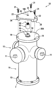
[0020] Figure 1 is an exploded upper perspective view of a first embodiment
of a hydrant monument and support plate detached from the hydrant;
[0021] Figure 1A is a lower perspective view of the support plate of FIG. 1 in
isolation;
[0022] Figure 1113 is a perspective view showing an embodiment of the survey
indicia of the hydrant monument shown in Fig. 1;
[0023] Figure 2 is a perspective view of part of the hydrant monument of FIG.
1, with the support plate mounted thereto;
CA 02734432 2011-03-21
[0024] Figure 2A is a partial cross-section view of the support plate mounted
on the hydrant monument as shown in Figure 2 taken along 2A-2A;
[0025] Figure 3 illustrates an exploded perspective view of a hydrant
monument like that in FIG. 1, with a support plate elevated above the hydrant
using standoff rods;
[0026] Figure 3A illustrates a support bracket that may be used with standoff
rods;
[0027] Figure 4 shows an exploded perspective view of a second
embodiment of a support plate and hydrant monument;
[0028] Figure 4A shows a bottom plan view of the embodiment shown in
Figure 4;
[0029] Figure 5 shows a perspective view of an embodiment of an
attachment device;
[0030] Figure 6 shows a bottom plan view of the attachment device shown in
Figure 5;
[0031] Figure 7 shows a third embodiment of the hydrant monument and
support plate;
[0032] Figure 7A shows the embodiment of Figure 7 having a support plate
mounted using standoff rods;
[0033] Figure 8 shows the embodiment shown in Figure 7 with a securing
strap;
[0034] Figure 9 shows a lower perspective view of a fourth embodiment;
[0035] Figure 10 shows a side view of the embodiment shown in Figure 9;
[0036] Figure 11 is a top view of a tribrach without an optical plummet;
6
CA 02734432 2011-03-21
[0037] Figure 12 is a lower perspective view of a tribrach;
[0038] Figure 13 is a perspective view of a total station attached to a
tribrach
and adapted to be mounted on a hydrant monument;
[0039] Figure 14 is a perspective view of a single prism target and fine level
adapter attached to the embodiment shown in Figures 9 and 10;
[0040] Figure 15 is a perspective view of another embodiment of a securing
device.
DETAILED DESCRIPTION
[0041] With reference to Figures 1-3, a support plate 10 is illustrated that
may
be generally triangular in shape. Plate 10 may be configured so it can be
mounted to a hydrant monument 12 and be used for mounting survey equipment
to the upper surface 10D of plate 10. Survey equipment may comprise survey
instruments, such as total station 130 (Fig. 13), or survey targets, such as
single
prism target 140 (Fig. 14). Plate 10 may be made from any suitable material
such as by way of example only a metal such as steel, aluminum, or a white
metal alloy.
[0042] Hydrant monument 12 may be generally constructed using a
conventional fire hydrant that may be interconnected to a municipal or private
water supply system. An example of a suitable hydrant may be a model D67M-P
fire hydrant made by Clow Canada. Hydrant monument 12 may have an
operating nut 14 to control the supply of water to nozzle caps 11. Nozzle caps
as
used hereinafter may refer to pumper caps or hose caps of hydrant monument
12.
[0043] Hydrant monument 12 may be configured with a top cover 30 that
retains the operating nut 14 and protects the interior of the hydrant. Top
cover
30 may have an upper surface 30A that is generally flat to facilitate
installation of
support plate 10. Generally, the barrel portion 19 of hydrant monument 12 is
7
CA 02734432 2011-03-21
oriented vertically or very close to vertically, facilitating the accurate
setup of
survey equipment over a survey reference point on hydrant monument 12.
[0044] Plate 10 may have an attachment aperture 28 to receive an attaching
device, such as attachment device 92, so that a portion of attachment device
92
extends through the attachment aperture 28 above upper surface 1 OD of plate
10
and can be connected to a survey instrument.
[0045] The lower surface of plate 10 may have a recessed area 24, extending
from and surrounding attachment aperture 28. Downwardly extending mounting
flanges 26 may be formed at the interface with the recessed area 24 with
generally flat lower surfaces 26A. This may provide flush contact with the
upper
surface 30A of top cover 30 of hydrant monument 12, when the plate 10 is
installed on hydrant monument 12. The precise dimensions or configuration of
the mounting flanges 26 may not be critical, although flush contact with the
top
30 of the hydrant monument 12 may facilitate efficient set up of survey
equipment when the upper surface of top 30 is generally flat.
[0046] Plate 10 may also have securing apertures 22 generally aligned with
corresponding mounting apertures 18 on hydrant monument 12. A securing
device, such as bolt 21 or unthreaded pin (not shown), plug (Figure 15), or
quick
release bolt may be received by each securing aperture 22 and corresponding
mounting aperture 18 to mount plate 10 on hydrant monument 12. Securing
apertures 22 and mounting apertures 18 may be threaded to receive bolts 21
having compatible threading. Similarly, when standoff rods 50 are used
mounting apertures 18 may be threaded to receive ends 53 of standoffs rods 50
having compatible threads.
[0047] Securing apertures 22 may be configured to be located proximate the
vertices of a triangle, for example an equilateral triangle, offset from the
vertices
1 OA, 1 OB and 1 OC of mounting plate 10, where mounting plate 10 has a
generally triangular shape. Configuring the securing apertures 22 in an
equilateral triangle assists in ensuring that the monument plate 10 provides a
8
CA 02734432 2011-03-21
stable base for the attachment of surveying equipment, and in particular
survey
instruments, such as total station 130.
[0048] In some embodiments, securing apertures 22 may be oversized such
that even with bolts received through apertures 22 in to apertures 18 in cover
30,
plate 10 may be moved transversely relative to surface 30A of top cover 30.
However, it will be appreciated that the position of apertures 18 relative to
opening 28 may in some embodiments determine where opening 18 will be
transversely positioned.
[0049] Top cover 30 may have a generally flat upper surface 30A, which may
assist in providing a stable platform to mount plate 10. However, hydrant
monument 12 may not have a top cover 30 with a generally flat upper surface
30A, possibly requiring modifications to mounting plate 10 and/or to the
hydrant
12 to ensure adequate performance.
[0050] Operating nut 14 may be located extending through top cover 30 of
hydrant monument 12 and may extend vertically upwards from the upper surface
30A thereof. Operating nut 14 is typically located at or proximate the center
of
top cover 30. Operating nut 14 may have a hollow channel 16 with an upper
opening that may act as a lubricating port.
[0051] The hydrant monument 12 may have a survey reference or control
point or location thereon, and such survey reference or control point may
include
survey indicia to identify the same. A point on the upper surface of operating
nut
14 (or the center thereof) may serve as the survey reference point for hydrant
monument 12, the position of which may be known in at least 2 dimensional non-
vertical space. The precise elevation of the upper surface of operating nut
14,
acting as a survey reference or control point, may also be known to a surveyor
or
may be determined with reference to other monuments having known vertical
elevations. The reference point may be the center of the top surface of
operating
nut 14. In other examples, the reference point may be at another location on
the
hydrant.
9
CA 02734432 2011-03-21
[0052] The term "survey indicia" as used herein refers to information
associated with a reference point that may be of value to a surveyor, such as
an
identifier that is uniquely associated with the reference point to permit a
surveyor
to ascertain the coordinates of the reference point. Similarly, survey indicia
may
also refer to the coordinates of the reference point itself, in embodiments
where
this is directly associated with a particular reference point in the field.
For
example, bolt 2 may be secured to base flange 13 as shown in Figure 1 B and
may have markings to uniquely identify a reference point, allowing a surveyor
to
ascertain the position of the reference point. In this case, the markings on
bolt 2
would be survey indicia associated with hydrant monument 12.
[0053] Attachment device 92 may be employed to secure a survey instrument
or a survey target to plate 10. As shown in Figures 5 and 6, attachment device
92 may have a securing end 94 to secure survey equipment, which may be
mounted on a tribrach 60, to plate 10. An example of a commercially available
tribrach that may be utilized are models ATR 95001 or ATR 95002 made by
Sokkia. Securing end 94 of attachment device 92 may have a diameter smaller
than attachment aperture 28. In some embodiments this may permit fine
transverse position adjustment of survey equipment, such as total station 130,
to
ensure that the survey equipment is centered over the operating nut 14 and the
reference point thereon. For example, when standoff rods 50 are used the
transverse position of the attachment device 92 may not be dictated by being
positioned over the operating nut 14. Additionally, if securing end 94 of
attachment device 92 has a diameter smaller than attachment aperture 28, this
may ensure that aperture 28 does not impede the positioning of attachment
device 92 on operating nut 14, thus allowing attachment device, and the survey
instrument attached thereto, to be appropriately positioned relative to the
reference point.
[0054] Securing end 94 may have a hollow interior channel 93 so that one can
see through attachment device 92 along a longitudinal axis. Hollow interior
channel 93 permits one to see through attachment device 92 from above to allow
CA 02734432 2011-03-21
a surveyor to look through an optical plummet (not shown) to center a survey
instrument over a reference point by moving attachment device 92 horizontally
within aperture 28. An optical plummet may be included as part of a tribrach
or
other equipment such as a total station or fine leveling adapter. Securing end
94
may also be threaded to secure survey equipment.
[0055] Attachment device 92 may also have a supporting end 95 that may
have a hollow interior cavity 96 to receive operating nut 14. Hollow interior
cavity
96 may be sized so that operating nut 14 may be snugly received within cavity
96
while permitting independent rotation of attachment device 92 relative to
operating nut 14. Permitting both operating nut 14 and attachment device 92 to
both rotate but independent of each other, assists in preventing undesirable
rotation of attached survey equipment upon rotation of operating nut 14.
[0056] With reference to Figure 2A, a support surface 91 may be defined at
the intersection of securing end 94 and supporting end 95, where supporting
end
95 has a diameter larger than securing end 93. The depth of hollow interior
cavity 96 may be slightly or significantly less than the height of operating
nut 14
so that the attachment device 92 does not contact the top surface 30A of
hydrant
monument cover 30. A gap 99 between the top surface 30A of hydrant cover
30, and the bottom of supporting end 95 may for example be in the range of %2
to
1 inch, to allow a wrench to be inserted by a fireman to turn operating nut
14, to
activate the fire hydrant. Additionally, the top of operating nut 14 may be
configured in relation to the position of attachment device 92 so that the top
of
operating nut 14 does not contact support surface 91 when survey equipment is
mounted to plate 10.
[0057] Attachment device 92 may be positioned so that operating nut 14 is
received by cavity 96 and securing end 94 extends through attachment aperture
28, so that securing end 94 extends above upper surface 1 OD of plate 10.
Attachment device 92 may then secure a survey instrument or survey target,
typically using a tribrach, to plate 10. When survey equipment is secured to
plate
11
CA 02734432 2011-03-21
using attachment device 92, support surface 91 may make secure and flush
contact with recessed area 24 on the lower surface of plate 10 to provide a
stable
mount that inhibits rotation of the attached survey equipment. Such a
configuration of attachment device 92 also facilitates independent rotation of
attachment device 92 and operating nut 14. The positioning of the attachment
device 92 on operating nut 14 may itself serve to properly transversely
position
the survey instrument attached to device 92 over a reference point on hydrant
monument 12, such as on operating nut 14.
[0058] Additionally, the position of apertures 18 relative to opening 28 can
be
configured such that opening 18 will be transversely positioned appropriately
to
allow attachment device 92 to be received on operating nut 14 so that device
92
is positioned over the reference point.
[0059] Attachment device 92 allows survey equipment to be mounted more
robustly to hydrant monument 12 using plate 10. Secure mounting of survey
instruments and sophisticated survey targets is important to ensure the proper
position and orientation is maintained, particularly given the weight of the
instruments. A survey instrument or survey target may be said to be securely
mounted when it is secured so that its base is stable in a generally
horizontal
plane and so that rotation of its base about a vertical axis is inhibited or
prevented. Preventing rotation about a vertical axis of survey instruments and
targets is important when conducting a survey to maintain proper orientation
and
to permit the precise measurement of angles between reference points when
using a survey instrument. Upon rotation of a survey instrument or survey
target,
proper orientation is lost and the correctness of subsequent measurements is
negatively impacted affecting the accuracy of the survey. For example, if a
survey instrument improperly rotates by 5 degrees during use, points that are
in
reality 45 degrees apart may be measured as only being 40 degrees apart.
Similarly, even very small rotations of a survey instrument may introduce
significant errors when surveying over large distances.
12
CA 02734432 2011-03-21
[0060] To secure survey equipment to plate 10, survey equipment may be
placed on upper surface 1 OD. Attachment device 92 may then be inserted
through attachment aperture 28, so that securing end 94 may be received by an
aperture formed in the survey equipment to be mounted. For example, securing
end 94 may be received in an aperture 68 of tribrach 60 (Fig. 12), with
tribrach 60
having survey equipment mounted to it, as described below. A secure mount of
plate 10 to tribrach 60 and survey equipment attached to tribrach 60, may be
achieved by threading securing end 94 into aperture 68 until the lower surface
62
is firmly held against upper surface 1 OD of plate 10 so that a stable mount
that
inhibits rotation about a vertical axis is provided.
[0061] Once survey equipment is secured to plate 10, plate 10 may be
attached to hydrant monument 12 by placing plate 10 on top cover 30 so that
cavity 96 of attachment device 92 receives operating nut 14, and securing
plate
is secured to top 30 with bolts 21. Bolts 21 may be threaded through securing
apertures 22 and mounting apertures 18 each having compatible threads.
Alternatively, in some applications / embodiments, bolts 21 may not be
threaded
and simply inserted into securing apertures 22 and corresponding mounting
apertures 18 to provide a stable mount of plate 10 to hydrant monument 12. In
this way, the survey equipment will have its base secured so that its
orientation
will not change from a desired generally horizontal plane orientation and
inhibit
rotation of survey equipment about a vertical axis.
[0062] It may be important to ensure that when plate 10 is secured to tribrach
60, that the transverse position of attachment device 92 relative to plate 10,
will
allow the plate to be mounted to cover 30. Thus, the tolerances may be such
that the transverse position of attachment device 92 is substantially defined
by
passing through aperture 28 in plate 10. In other embodiments, the attachment
device may not have its transverse position secured (e.g. it is not tightened
to
plate 10) until after plate 10 has been mounted to the hydrant cover 30. Thus
a
gap may be provided between plate 30 between flanges 26 that is sufficient to
permit either an individuals fingers or a suitable tool to engage the
attachment
13
CA 02734432 2011-03-21
device to secure the attachment device to the plate 10 and tribrach 60, when
attachment device is mounted on operating nut 14.
[0063] Other forms of securing devices may also be used to secure plate 10
to hydrant monument 12. For example, a quick release plug 400 (Figure 15) may
be used to secure plate 10 to hydrant monument 12 to provide a stable mount
that inhibits rotation. Expandable end 406 may be inserted through securing
apertures 22 and at least partially received in mounting apertures 18. Handle
402 may then be pivoted about hinge 404 to cause expandable end 406 to
expand within securing apertures 22 and mounting apertures 18 to provide a
relatively secure mount. Devices such as plug 400 are readily available and
are
not described in further detail herein. Alternatively, quick insertion and
release
bolts, such as those described in US Patent No. 4,478,546, the contents of
which
are hereby incorporated herein by reference, may be used to secure plate 10 to
hydrant monument 12. Having securing devices that enable plate 10 to be
quickly and easily removed may be advantageous as it permits ready access to
operating nut 14 to activate the flow of water from hydrant monument 12 in
emergency situations. The ability to quickly and easily remove plate 10, may
assist to alleviate regulatory concerns that may otherwise limit the use of
plate 10
in surveying using hydrant monuments.
[0064] In other embodiments, standoff rods 50 (Fig. 3) may be used to elevate
plate 10 above the top cover 30 of hydrant monument 12. Standoff rods 50 may
have ends 53 compatible with mounting apertures 18 to secure standoff rods 50
to hydrant monument 12. Standoff rods 50 may also have apertures 51 to
receive securing devices, such as bolts 21, each having compatible threads.
Plate 10 may be secured to standoff rods 50 by placing bolts 21 through
securing
apertures 22 and into apertures 51 of standoff rods 50 to attach plate 10 to
standoff rods 50 and thereby to hydrant monument 12.
[0065] It may be desirable to have plate 10 elevated above the top cover 30 of
hydrant monument 12 to make it easier for the surveyor to take measurements
14
CA 02734432 2011-03-21
using a survey instrument, such as total station 130. Similarly, the terrain
surrounding a hydrant monument 12 may require monument plate 10 be elevated
such as, for example, where the terrain is particularly hilly, or when a snow
bank
would otherwise obstruct a surveyors line of sight to a survey target.
Standoff
rods 50 should be of a sufficient diameter and constructed from a suitable
material to ensure that plate 10 is sufficiently stable to permit a surveyor
to take
accurate measurements using an attached survey instrument. While three
standoff rods 50 are ideal, more than three rods could be employed to further
secure the plate 10 to hydrant monument 12.
[0066] In another method of attaching plate 10 to hydrant monument 12 when
using standoff rods 50, standoff rods 50 may first be secured to hydrant
monument 12 by securing ends 53 in mounting apertures 18. Plate 10 may then
be secured to standoff rods by placing bolts 21 through securing apertures 22
to
be received in ends 51. Survey equipment may then be placed on upper surface
1 OD. Attachment device 92 may then be inserted through attachment aperture
28 and received by an aperture of the survey equipment to be secured. For
example, securing end 94 may be received by aperture 68 of tribrach 60 when a
tribrach is used to secure survey equipment to plate 10.
[0067] Attachment device 92 may be used to center a survey instrument over
the operating nut 14 and to secure the survey instrument to plate 10.
Centering
of a survey instrument over operating nut 14 may be possible using attachment
device 92 in circumstances where the diameter of securing end 94 is smaller
than the diameter of attachment aperture 28 and thus end 94 can be moved
transversely within aperture 28. An optical plummet (not shown) which is often
part of a known tribrach or other survey equipment may be used to facilitate
centering over operating nut 14. A surveyor may look through the hollow
interior
of attachment device 92 and position the survey equipment so that it may be
centered over a reference point, such as a reference point on the top of
operating
nut 14. When standoffs are employed, the ability to center survey equipment
CA 02734432 2011-03-21
over a reference point may be of increased importance compared to
embodiments where plate 10 is mounted closer to top cover 30.
[0068] As illustrated in Figures 3 and 3A, depending upon the length and
design of standoff rods 50, it may be desirable to have a supplementary
supporting apparatus, such as a support bracket 500 located between plate 10
and top cover 30 to provide additional stability. Support bracket 500 may have
apertures 528 to receive standoff rods 50. Support bracket 500 may also have
an aperture 506 to facilitate centering over a reference point using an
optical
plummet. Where desired for use with support bracket 500 standoff rods may
have apertures 502 for insertion of a support 504. To mount plate 10 using
standoffs and support bracket 500, standoffs may first be secured to hydrant
monument 12 as previously described. Supports 504 may then be placed into
apertures 502. Standoff rods 50 may then be inserted into apertures 528 of
support bracket 500 and support bracket 500 lowered into position to be
supported by supports 504. Other methods of and devices for providing
additional support for platel0, may also be used in particular applications.
[0069] Survey equipment, such as survey instruments and targets, are often
mounted upon a tribrach. The tribrach is then typically secured to a tripod
(not
shown) to position the survey instrument or target for use in the field. An
exemplary tribrach 60 is shown in Figures 11 and 12. Tribrach 60 has an upper
plate 64 connected to lower plate 62 with three bolts having thumb screws 65
to
allow adjustment. Adjusting thumb screws 65 allows upper plate 64 to be moved
relative to lower plate 62 permitting upper surface 64 to be leveled. Upper
surface 64 may also have a leveling device 61 to assist in leveling upper
surface
64. Both the upper plate 64 and lower plate 62 are typically triangular to
provide
a stable platform for survey equipment.
[0070] Lower plate 62 of tribrach 60 may have an aperture 68 to secure
tribrach 60 to plate 10. Aperture 68 may be threaded to receive securing end
94
of attachment device 92 having corresponding threads to secure lower surface
16
CA 02734432 2011-03-21
62 to plate 10. Lower surface 62 may be secured to plate 10 so that lower
surface 62 of tribrach 60 is flush mounted on upper surface 10D of plate 10 to
provide stability. Survey equipment such as a total station 130 may be secured
to upper surface 64 by inserting projections (not shown) of survey equipment
into
apertures 67 and clamping projections securely in place according to known
methods.
[0071] Ensuring that a level surface is provided is particularly important for
survey instruments, such as total station 130 and sophisticated survey
targets.
Permitting survey equipment to be mounted on a hydrant monument 12 using
tribrach 60 is one method of providing a stable platform that may be leveled.
Mounting survey equipment using tribrach 60 is advantageous because tribrachs
are widely used by surveyors and existing equipment may be readily adapted for
use with plate 10 to mount to hydrant monument 12. To facilitate the use of a
common tribrach 60, securing end 94 may have a 5/8" diameter and be threaded
with 11 threads per inch to be received by aperture 68.
[0072] Securing survey equipment to plate 10 using a tribrach such as
tribrach 60 is particularly advantageous. As common survey targets and survey
instruments are also generally designed to be secured to tribrach 60 it is
possible
to interchange a survey instrument with a survey target without removing the
tribrach from the hyrdant monument. Importantly, when survey instruments or
survey targets are interchanged in this manner a high degree of accuracy can
be
maintained as the survey equipment or survey instrument can be supported in
the same position.
[0073] General methods of surveying are well known in the art, and are not
described in detail hereinafter. A surveyor wishing to conduct a survey may
attach a survey instrument over a reference point of hydrant monument 12. A
survey instrument may be attached to a hydrant monument 12, for example,
using plate 10 and tribrach 60. Once a survey instrument is attached to a
hydrant monument 12 having a position known in 2 dimensional vertical space, a
17
CA 02734432 2011-03-21
surveyor may sight from a reference point on a hydrant monument 12 to a survey
target. The survey instrument attached to a hydrant monument 12 may be, for
example, a total station 130. Additionally, a surveyor may sight to a target
from
the reference point, when the position of the reference point is also known in
a
vertical direction to assist in making a survey.
[0074] With reference to Figure 14, similarly, survey targets, such as a
single
prism target 140 may be attached to a reference point on a hydrant monument
12, where the position of the reference point may be known in at least 2
dimensional space. A surveyor may then sight to the target attached to a
reference point of a hydrant monument 12 to assist in making a survey.
[0075] Modifications to plate 10 may be made where the upper surface 130a
of top cover 130 of a hydrant monument 112 is not flat or approximately flat.
Many existing hydrant monuments 112 have top covers 130 that are not
generally flat but are otherwise suitable for the attachment of survey
equipment
and use as a reference point by a surveyor.
[0076] Support plate 180 as shown in Figure 4 is suitable for attachment to a
hydrant monument 112 having a curved or domed top cover 130 and flange 115
as part of top cover 130. Plate 180 is preferable for use with survey targets
although certain types of survey instruments may also be used with plate 180.
[0077] Additional details of an exemplary hydrant monument 112 having a
curved top cover 130 are shown in Figure 4. Flange 115 may be located at the
bottom of top cover 130 and make flush contact with flange 117 of barrel
portion
119 so that apertures (not shown) on flanges 115 and 117 are aligned. In this
manner, top cover 130 may be secured to barrel portion 119 using bolts (not
shown) received in the apertures in a conventional manner. Mounting apertures
118 may be located on flanges 115 and 117 to receive securing devices, such
mounting protrusions 123 extending from sidewall 181, to facilitate secure
mounting of support plate 180 on flange 115. Alternatively, support plate 180
may be modified to have securing apertures (not shown) extending through
18
CA 02734432 2011-03-21
sidewall 181 so that bolts (not shown) may be inserted through securing
apertures and received by mounting apertures 118 to secure support plate 180
to
flange 115.
[0078] Attachment device 192 may be used to secure survey equipment, such
as a survey target, using tribrach 60 as previously described with reference
to
attachment device 92, before mounting support plate 180 to hydrant monument
112. Attachment device 192 may be similar to attachment device 92 or may be
modified for particular applications. Survey equipment may be placed on the
upper surface of support plate 180 and secured with attachment device 192, as
previously described with reference to plate 10. Support plate 180 may then be
placed on hydrant monument 112 so that mounting projections 123 are received
by apertures 118 to prevent rotation of support plate 180 and provide a stable
base for use with certain types of survey equipment. However, the tribrach may
be used as an intermediary between top plate 180 and the survey equipment.
[0079] Support plate 200, shown in Figures 7 and 8, is another embodiment
suitable for securing survey equipment to a hydrant monument 212, including
hydrant monuments having curved or domed tops. Support plate 200 may have
an attachment aperture 228 to receive an attachment device, (not shown) to
secure survey equipment. A survey instrument, such as total station 130, or a
survey target, such as single prism target 140, may be secured to plate 200
using an attachment device such as attachment device 92 as previously
described with reference to plate 10. Specifically, an attachment device could
be
placed over operating nut 214 and make flush contact with the lower surface of
support plate 200 to center survey equipment over operating nut 214 and
provide
a stable mount that permits independent rotation of the attachment device and
operating nut 214, while providing a stable mount that also inhibits rotation
of the
attached survey equipment.
[0080] Plate 200 may have an upper surface 202 and attachment arms 204.
The attachment arms 204 may extend downward and may each have a nozzle
19
CA 02734432 2011-03-21
aperture 208 to receive nozzle caps 211 of hydrant monument 212. Attachment
arms may be secured in place by any suitable means such as a pin in each hole
of each cap 211 (not shown). Attachment arms 204 may thus secure plate 200
to hydrant monument 212 to provide a stable mounting platform for survey
equipment, particularly survey instruments.
[0081] As shown in Figure 8, a stability strap 210 may extend around the
barrel 219 of hydrant monument 212 and may be connected to each attachment
arm 204 to increase the stability of plate 200 when mounted to hydrant
monument 212. Strap 210 may also have a buckle 212 to permit strap 210 to be
tightened to assist in providing a stable plate 200. Alternatively, a
stability strap
having caps to receive nozzle caps 211 could be employed and tightened.
Further details of a suitable strap having caps to receive nozzle caps 211 is
described in US Patent No. 6,691,732, the contents of which are hereby
incorporated herein by reference.
[0082] As shown in Figure 7A, plate 200 may also have securing apertures
222 when it is desired to elevate survey equipment above top cover 230 of
hydrant monument 212. This may be accomplished using standoff rods 50.
Securing apertures 222 may receive ends 53 of standoff rods 50 to secure
standoff rods 50 to plate 200 to provide a base for the attachment of an
elevated
support plate 250. Elevated support plate 250 may be similar to plate 10
previously described. Plate 250 may then be secured using bolts 21 received by
securing apertures 22 and apertures 51 to secure plate 250 to standoff rods
50.
Other securing devices as described above may also be used to secure plate
250 to standoff rods 50. Survey equipment and plate 250 may then be mounted
as previously described with reference to plate 10 when standoff rods 50 are
used. Where plate 200 is not desired for use with standoff rods 50, securing
apertures 222 may not be present.
[0083] Monument plate 200 and attachment arms 204 may be constructed of
a material, such as for example aluminum or stainless steel to ensure the
upper
CA 02734432 2011-03-21
surface 202 of monument plate 200 provides a stable and rigid surface for the
attachment of a survey instrument, such as total station 130. For example,
plate
200 could be comprised of aluminum '/ inches thick and having attachment
arms of the same thickness that are 2.5 to 3 inches wide and provide
acceptable
performance in certain applications.
[0084] Alternatively, support plate 200 may be secured to hydrant monument
212 using only 2 attachment arms. Attachment arms may be generally the same
as attachment arms 204, except that the thickness and width may need to be
modified to provide sufficient stability for particular applications. Persons
skilled
in the art will appreciate that using 3 attachment arms provides greater
stability,
however, the use of 2 attachment arms may be suitable for certain applications
and may reduce manufacturing costs.
[0085] Another embodiment suitable to secure survey equipment to a hydrant
monument is illustrated in Figures 9 and 10. In this embodiment, a support
device 320 is comprised of a tribrach that may be mounted directly upon the
upper surface 330A of top cover 330 of a hydrant monument 312. The support
device may have a modified lower plate 362 suitable to provide a stable
platform
when mounted to a generally flat upper surface 330A of hydrant monument 312.
[0086] Support device 320 has an upper plate 364 and lower plate 362
connected by thumb screws 365. Adjustment of thumb screws 365 adjusts upper
surface 364 relative to lower plate 362 allowing upper plate 364 to be
leveled, in
the same manner as a traditional tribrach. Survey equipment may be secured to
the upper surface 364 of the tribrach as previously described in relation to
Figures 11 and 12.
[0087] Lower plate 362 may have downwardly extending mounting projections
323 extending to securely mount said support device 320 to upper surface 330a
of hydrant monument 312. Mounting projections 323 may securely mount
support device 320 by abutting upper surface 330A of hydrant monument 312 to
21
CA 02734432 2011-03-21
provide support and/or inhibit rotation of lower surface 362. Mounting
projections
323 may be mounting flanges 322 having pins 326.
[0088] As illustrated in Figures 9 and 10, mounting flanges 322 may extend
from lower surface 362 and make flush contact with upper surface 330A of top
330 when attachment device 320 is placed on upper surface 330A of hydrant
monument 312. The precise configuration of mounting flanges 322 may vary.
However, positioning mounting flanges 322 at or near vertices 320A, 320B, and
320C of generally triangular plate 362 may increase stability. Pins 326 may
also
extend from the lower surface of mounting flanges 322. Pins 326 may be
received by corresponding apertures 328 located on at upper surface 330A of
top
330 of hydrant monument 312 to assist in providing stability and inhibit
rotation of
support device 320. Again, the precise configuration of apertures 328 and pins
326 may vary and provide a secure mounting of device 320 to hydrant monument
312. Alternatively, mounting projections 323 may be pins 326 extending from
lower surface 362 and received by apertures 328 without having mounting
flanges 322 with suitable modification. Mounting projections 323 may be
modified in other ways provided a means to securely mount and inhibit rotation
of
attachment device 320 is achieved.
[0089] As an additional measure to secure the plate 362 to top cover 330 for
hydrant monument 312, securing end 394 of attachment device 392 may be
received by aperture 368 located on lower plate 362. Attachment device 392
may be similar to attachment device 92. Securing end 394 and aperture 368
may have corresponding threads to permit secure attachment. Attachment
device 392 may be positioned so that interior cavity 396 is placed over
operating
nut 314 and have securing end 394 inserted into aperture 368 to center
securing
device 320 over operating nut 314 to facilitate placement of survey equipment
over a reference point in a manner similar to that previously described with
reference to attachment device 92 and plate 10.
22
CA 02734432 2011-03-21
[0090] To use support device 320, survey equipment may first be secured to
upper surface 364, in a similar manner to as described above with reference to
tribrach 60. Attachment device 392 may then be threaded into attachment
aperture 368. Support device 320, with survey equipment secured thereto, may
then be placed on top 330 so that mounting projections 323 may be received by
apertures 328 and operating nut 14 is received within attachment device 392.
Attachment device 392 may have a cavity to receive operating nut 314 in a
similar manner to attachment device 92.
[0091] Support plate 10 and other embodiments of the support plate or
support device 320 may also be adapted to receive a GPS unit as one particular
type of survey equipment. The use of a GPS receiver tied to a hydrant
monument 12 with a known physical location may be used as a base station and
may permit a GPS unit to initialize faster with fewer satellites, according to
known
methods.
[0092] Securing a GPS unit to a hydrant monument 12 is advantageous
compared to securing a GPS unit to a tripod. Often GPS units are setup for
extended periods of time where the surveyor is not in the immediate area,
exposing expensive GPS units to possible theft or vandalism. Securing a GPS
unit to a hydrant monument 12 provides a securely fixed platform to secure a
GPS unit using for example, a locking cable, to minimize the risk of theft and
vandalism.
[0093] Various types of sophisticated survey equipment may be mounted to
hydrant monuments using the devices described above. For example, total
station 130 is shown attached to hydrant monument 12 using plate 10 and
tribrach 60 in Figure 13. Similarly, single prism target 140 and fine level
adapter
142 are shown attached to support device 120 in Figure 14.
[0094] Having regard to the foregoing, it will be appreciated that hydrant
monuments have significant advantages over conventional survey monuments in
23
CA 02734432 2011-03-21
providing a platform on which sophisticated survey instruments and survey
targets may be mounted.
[0095] When introducing elements of the present invention or the
embodiments thereof, the articles "a," "an," "the," and "said" are intended to
mean
that there are one or more of the elements. The terms "comprising,"
"including,"
and "having" are intended to be inclusive and mean that there may be
additional
elements other than the listed elements.
[0096] Of course, the above described embodiments, are intended to be
illustrative only and in no way limiting. The described embodiments of
carrying
out the invention, are susceptible to many modifications of form, arrangement
of
parts, details and order of operation. The invention, rather, is intended to
encompass all such modification within its scope, as defined by the claims.
24