Note: Descriptions are shown in the official language in which they were submitted.
CA 02734494 2011-02-16
WO 2010/027678 PCT/US2009/054394
MEDICAL DEVICES HAVING INORGANIC COATINGS
FOR THERAPEUTIC AGENT DELIVERY
RELATED APPLICATIONS
[0001] This application claims priority from United States provisional
application
61/092,347, filed August 27, 2008, which is incorporated by reference herein
in its
entirety.
TECHNICAL FIELD
[0002] This invention relates to medical devices, and more particularly, to
medical
devices having inorganic coatings that allow the release of underlying
therapeutic agents.
BACKGROUND OF THE INVENTION
[0003] The in-situ delivery of therapeutic agents within the body of a patient
is common
in the practice of modern medicine. In-situ delivery of therapeutic agents is
often
implemented using medical devices that may be temporarily or permanently
placed at a
target site within the body. These medical devices can be maintained, as
required, at their
target sites for short or prolonged periods of time, in order to deliver
therapeutic agents to
the target site.
[0004] For example, in recent years, drug eluting coronary stents, which are
commercially available from Boston Scientific Corp. (TAXUS), Johnson & Johnson
(CYPHER) and others, have been widely used for maintaining vessel patency
after
balloon angioplasty. These products are based on metallic expandable stents
with
biostable polymer coatings that release antirestenotic drugs at a controlled
rate and total
dose.
SUMMARY OF THE INVENTION
[0005] According to an aspect of the invention, medical devices are provided
that
comprise a substrate, at least one therapeutic agent disposed over or in the
substrate, and
at least one inorganic layer disposed over the therapeutic agent and the
substrate, wherein
the inorganic layer is either a porous inorganic layer or is a non-porous
layer that
becomes a porous inorganic layer in vivo.
1
CA 02734494 2011-02-16
WO 2010/027678 PCT/US2009/054394
[0006] Other aspects of the invention comprise methods for forming medical
devices.
[0007] An advantage of the present invention is that medical devices may be
provided, in
which the release of therapeutic agents is controlled.
[0008] Another advantage of the present invention is that therapeutic-agent
releasing
medical devices are provided, which have inorganic outer layers. Inorganic
materials
commonly have enhanced biocompatibility, including enhanced vascular
biocompatibility.
[0009] Another advantage of the present invention is that medical devices with
release-
regulating inorganic layers may be provided, in which it is not necessary to
pass
therapeutic agent into or through the inorganic layers in order to load the
medical devices
with the therapeutic agent.
[0010] These and other embodiments and advantages of the present invention
will
become immediately apparent to those of ordinary skill in the art upon review
of the
Detailed Description and Claims to follow.
BRIEF DESCRIPTION OF THE DRAWINGS
[0011] Figs. 1-5 are schematic cross-sectional illustrations of medical
devices in
accordance with various embodiments of the invention.
[0012] Fig. 6A is a schematic cross-sectional illustration of a medical device
in
accordance with an embodiment of the invention. Fig. 6B is a schematic cross-
section
illustrating the medical device of Fig. 6A after being implanted or inserted
into a subject
for a period of time.
[0013] Fig. 7A is a schematic cross-sectional illustration of a medical device
in
accordance with an embodiment of the invention. Fig. 7B is a schematic cross-
section
illustrating the medical device of Fig. 7A after being implanted or inserted
into a subject
for a period of time.
[0014] Fig. 8 is a schematic illustration of an apparatus for forming medical
devices in
accordance with an embodiment of the invention.
2
CA 02734494 2011-02-16
WO 2010/027678 PCT/US2009/054394
[0015] Fig. 9A is a scanning electron micrograph (SEM) (5000x) of a
substantially
smooth coating. Figs. 9B and 9C are SEMs of coatings that are suitable for use
as rough
underlying layers, in accordance with an embodiment of the invention.
[0016] Fig. 1OA is a schematic cross-sectional illustration of a medical
device prior to
application of an inorganic surface layer, in accordance with an embodiment of
the
invention. Fig. 10B is a schematic cross-section illustrating the medical
device of Fig.
10A, after application of an inorganic surface layer.
DETAILED DESCRIPTION
[0017] According to an aspect of the invention, medical devices are provided
that
comprise a substrate, at least one therapeutic agent disposed over or in the
substrate, and
at least one inorganic layer disposed over the therapeutic agent and the
substrate, wherein
the inorganic layer is either a porous inorganic layer or is a non-porous
layer that
eventually becomes a porous inorganic layer in vivo (also referred to herein
as a "pro-
porous" inorganic layer).
[0018] In some embodiments, the inorganic layers are nanoporous inorganic
layers.
However, the present invention is not limited to nanoporous inorganic layers.
Inorganic
layers of any porosity may be employed.
[0019] Examples of medical devices benefiting from the present invention vary
widely
and include implantable or insertable medical devices, for example, stents
(including
coronary vascular stents, peripheral vascular stents, cerebral, urethral,
ureteral, biliary,
tracheal, gastrointestinal and esophageal stents), stent coverings, stent
grafts, vascular
grafts, abdominal aortic aneurysm (AAA) devices (e.g., AAA stents, AAA
grafts),
vascular access ports, dialysis ports, catheters (e.g., urological catheters
or vascular
catheters such as balloon catheters and various central venous catheters),
guide wires,
balloons, filters (e.g., vena cava filters and mesh filters for distil
protection devices),
embolization devices including cerebral aneurysm filler coils (including
Guglielmi
detachable coils and metal coils), septal defect closure devices, myocardial
plugs,
patches, electrical stimulation leads, including leads for pacemakers, leads
for
implantable cardioverter-defibrillators, leads for spinal cord stimulation
systems, leads for
3
CA 02734494 2011-02-16
WO 2010/027678 PCT/US2009/054394
deep brain stimulation systems, leads for peripheral nerve stimulation
systems, leads for
cochlear implants and leads for retinal implants, ventricular assist devices
including left
ventricular assist hearts and pumps, total artificial hearts, shunts, valves
including heart
valves and vascular valves, anastomosis clips and rings, tissue bulking
devices, and tissue
engineering scaffolds for cartilage, bone, skin and other in vivo tissue
regeneration,
sutures, suture anchors, tissue staples and ligating clips at surgical sites,
cannulae, metal
wire ligatures, urethral slings, hernia "meshes", artificial ligaments,
orthopedic prosthesis
such as bone grafts, bone plates, fins and fusion devices, joint prostheses,
orthopedic
fixation devices such as interference screws in the ankle, knee, and hand
areas, tacks for
ligament attachment and meniscal repair, rods and pins for fracture fixation,
screws and
plates for craniomaxillofacial repair, dental implants, or other devices that
are implanted
or inserted into the body and from which therapeutic agent is released.
[0020] Thus, in some embodiments the devices of the invention may simply
provide for
therapeutic agent release, whereas in other embodiments, they are configured
to provide a
therapeutic function beyond controlled therapeutic agent release, for
instance, providing
mechanical, thermal, magnetic and/or electrical functions within the body,
among other
many possible functions.
[0021] The medical devices of the present invention include, for example,
implantable
and insertable medical devices that are used for systemic treatment, as well
as those that
are used for the localized treatment of any mammalian tissue or organ. Non-
limiting
examples are tumors; organs including the heart, coronary and peripheral
vascular system
(referred to overall as "the vasculature"), the urogenital system, including
kidneys,
bladder, urethra, ureters, prostate, vagina, uterus and ovaries, eyes, ears,
spine, nervous
system, lungs, trachea, esophagus, intestines, stomach, brain, liver and
pancreas, skeletal
muscle, smooth muscle, breast, dermal tissue, cartilage, tooth and bone.
[0022] As used herein, "treatment" refers to the prevention of a disease or
condition, the
reduction or elimination of symptoms associated with a disease or condition,
or the
substantial or complete elimination of a disease or condition. Subjects are
vertebrate
subjects, more typically mammalian subjects including human subjects, pets and
livestock.
4
CA 02734494 2011-02-16
WO 2010/027678 PCT/US2009/054394
[0023] Substrate materials for the medical devices of the present invention
may vary
widely in composition and are not limited to any particular material. They can
be
selected from a range of biostable materials and biodisintegrable materials
(i.e., materials
that, upon placement in the body, are dissolved, degraded, resorbed, and/or
otherwise
removed from the device), including (a) organic materials (i.e., materials
containing
organic species, typically 50 wt% or more, for example, from 50 wt% to 75 wt%
to 90
wt% to 95 wt% to 97.5 wt% to 99 wt% or more) such as polymeric materials
(i.e.,
materials containing polymers, typically 50 wt% or more polymers, for example,
from 50
wt% to 75 wt% to 90 wt% to 95 wt% to 97.5 wt% to 99 wt% or more) and
biologics, (b)
inorganic materials (i.e., materials containing inorganic species, typically
50 wt% or
more, for example, from 50 wt% to 75 wt% to 90 wt% to 95 wt% to 97.5 wt% to 99
wt%
or more), such as metallic inorganic materials (i.e., materials containing
metals, typically
50 wt% or more, for example, from 50 wt% to 75 wt% to 90 wt% to 95 wt% to 97.5
wt%
to 99 wt% or more) and non-metallic inorganic materials (i.e., materials
containing non-
metallic inorganic materials, typically 50 wt% or more, for example, from 50
wt% to 75
wt% to 90 wt% to 95 wt% to 97.5 wt% to 99 wt% or more) (e.g., including
carbon,
semiconductors, glasses and ceramics, which may contain various metal- and non-
metal-
oxides, various metal- and non-metal-nitrides, various metal- and non-metal-
carbides,
various metal- and non-metal-borides, various metal- and non-metal-phosphates,
and
various metal- and non-metal-sulfides, among others), and (c) hybrid materials
(e.g.,
hybrid organic-inorganic materials, for instance, polymer/metallic inorganic
and
polymer/non-metallic inorganic hybrids).
[0024] Specific examples of inorganic non-metallic materials may be selected,
for
example, from materials containing one or more of the following: metal oxide
ceramics,
including aluminum oxides and transition metal oxides (e.g., oxides of
titanium,
zirconium, hafnium, tantalum, molybdenum, tungsten, rhenium, iron, niobium,
and
iridium); silicon; silicon-based ceramics, such as those containing silicon
nitrides, silicon
carbides and silicon oxides (sometimes referred to as glass ceramics); calcium
phosphate
ceramics (e.g., hydroxyapatite); carbon; and carbon-based, ceramic-like
materials such as
carbon nitrides.
CA 02734494 2011-02-16
WO 2010/027678 PCT/US2009/054394
[0025] Specific examples of metallic materials may be selected, for example,
from metals
such as gold, iron, niobium, platinum, palladium, iridium, osmium, rhodium,
titanium,
tantalum, tungsten, ruthenium, zinc, and magnesium, among others, and alloys
such as
those comprising iron and chromium (e.g., stainless steels, including platinum-
enriched
radiopaque stainless steel), niobium alloys, titanium alloys, alloys
comprising nickel and
titanium (e.g., Nitinol), alloys comprising cobalt and chromium, including
alloys that
comprise cobalt, chromium and iron (e.g., elgiloy alloys), alloys comprising
nickel, cobalt
and chromium (e.g., MP 35N), alloys comprising cobalt, chromium, tungsten and
nickel
(e.g., L605), alloys comprising nickel and chromium (e.g., inconel alloys),
and
biodisintegrable alloys including alloys of magnesium, zinc and/or iron (and
their alloys
with combinations of Ce, Ca, Al, Zr and Li), among others (e.g., alloys of
magnesium
including its alloys that comprises one or more of Fe, Ce, Al, Ca, Zn, Zr, La
and Li,
alloys of iron including its alloys that comprise one or more of Mg, Ce, Al,
Ca, Zn, Zr,
La and Li, alloys of zinc including its alloys that comprise one or more of
Fe, Mg, Ce, Al,
Ca, Zr, La and Li, etc.).
[0026] Specific examples of organic materials include polymers (which may be
biostable
or biodisintegrable) and other high and low molecular weight organic
materials, and may
be selected, for example, from suitable materials containing one or more of
the following:
polycarboxylic acid homopolymers and copolymers including polyacrylic acid,
alkyl
acrylate and alkyl methacrylate homopolymers and copolymers, including
poly(methyl
methacrylate-b-n-butyl acrylate-b-methyl methacrylate) and poly(styrene-b-n-
butyl
acrylate-b- styrene) triblock copolymers, polyamides including nylon 6,6,
nylon 12, and
polyether-block-polyamide copolymers (e.g., Pebax resins), vinyl homopolymers
and
copolymers including polyvinyl alcohol, polyvinylpyrrolidone, polyvinyl
halides such as
polyvinyl chlorides and ethylene-vinyl acetate copolymers (EVA), vinyl
aromatic
homopolymers and copolymers such as polystyrene, styrene-maleic anhydride
copolymers, vinyl aromatic-alkene copolymers including styrene-butadiene
copolymers,
styrene-ethylene-butylene copolymers (e.g., a poly(styrene-b-ethylene/butylene-
b-styrene
(SEBS) copolymer, available as Kraton G series polymers), styrene-isoprene
copolymers (e.g., poly(styrene- b-isoprene- b-styrene), acrylonitrile-styrene
copolymers,
acrylonitrile-butadiene-styrene copolymers, styrene-butadiene copolymers and
styrene-
6
CA 02734494 2011-02-16
WO 2010/027678 PCT/US2009/054394
isobutylene copolymers (e.g., polyisobutylene-polystyrene block copolymers
such as
poly(styrene-b-isobutylene-b-styrene) or SIBS, which is described, for
instance, in United
States Patent No. 6,545,097 to Pinchuk et al.), ionomers, polyesters including
polyethylene terephthalate and aliphatic polyesters such as homopolymers and
copolymers of lactide (which includes d-,1- and meso-lactide) (e.g., poly(L-
lactide) and
poly(d,l-lactide), glycolide (glycolic acid), and epsilon-caprolactone,
including
poly(lactide-co-glycolides) such as poly(1-lactide-co-glycolide) and poly(d,l-
lactide-co-
glycolide), polycarbonates including trimethylene carbonate (and its alkyl
derivatives),
polyanhydrides, polyorthoesters, polyether homopolymers and copolymers
including
polyalkylene oxide polymers such as polyethylene oxide (PEO) and polyether
ether
ketones, polyolefin homopolymers and copolymers, including polyalkylenes such
as
polypropylene, polyethylene, polybutylenes (such as polybut-1-ene and
polyisobutylene),
polyolefin elastomers (e.g., santoprene) and ethylene propylene diene monomer
(EPDM)
rubbers, fluorinated homopolymers and copolymers, including
polytetrafluoroethylene
(PTFE), poly(tetrafluoroethylene-co-hexafluoropropene) (FEP), modified
ethylene-
tetrafluoroethylene copolymers (ETFE) and polyvinylidene fluoride (PVDF),
silicone
homopolymers and copolymers including polydimethylsiloxane, polyurethanes,
biopolymers such as polypeptides, proteins, polysaccharides, fibrin,
fibrinogen, collagen,
elastin, chitosan, gelatin, starch, and glycosaminoglycans such as hyaluronic
acid; as well
as blends and further copolymers of the above.
[0027] The foregoing polymers may be provided in a number of configurations,
which
may be selected, for example, from cyclic, linear and branched configurations.
Branched
configurations include star-shaped configurations (e.g., configurations in
which three or
more chains emanate from a single branch point, such as a seed molecule), comb
configurations (e.g., configurations having a main chain and a plurality of
side chains),
dendritic configurations (e.g., arborescent and hyperbranched polymers),
networked (e.g.,
crosslinked) configurations, and so forth.
[0028] As indicated above, in one aspect of the invention, medical devices are
provided
that comprise, in addition to a substrate, at least one therapeutic agent
disposed over or in
the substrate, and at least one porous/pro-porous inorganic layer disposed
over the
therapeutic agent. In some embodiments, the therapeutic agent is provided
within the
7
CA 02734494 2011-02-16
WO 2010/027678 PCT/US2009/054394
substrate. In some embodiments, the therapeutic agent is provided in a
distinct
therapeutic-agent-containing layer (also referred to herein as a "therapeutic
layer")
between the substrate and porous/pro-porous inorganic layer.
[0029] As used herein a "layer" of a given material is a region of that
material whose
thickness is small compared to both its length and width (e.g., its length and
width are
each at least four times as great as its thickness). Terms such as "film,"
"layer" and
"coating" may be used interchangeably herein. As used herein a layer need not
be planar,
for example, taking on the contours of an underlying substrate. A layer can be
discontinuous, providing only partial coverage of an underlying structure
(e.g., made up
of a collection of two or more, sometimes many more, material regions).
[0030] For example, a layer may be provided over an underlying substrate in a
desired
pattern using suitable applicator (e.g., ink jet device, pen, brush, roller,
etc.) or using a
suitable masking technique. As a more specific example, in certain embodiments
of the
invention, a patterned therapeutic layer is provided over an underlying
substrate. Because
distinct surface regions of the substrate are not covered by the therapeutic
layer in such
embodiments, this may be advantageous, for example, in that direct contact
(and bonding)
is possible between the substrate and an overlying porous/pro-porous inorganic
layer.
[0031] Therapeutic layer may contain, for example, from 1 wt% or less to 2 wt%
to 5
wt% to 10 wt% to 25 wt% to 50 wt% to 75 wt% to 90 wt% to 95 wt% to 97.5 wt% to
99
wt% or more of a single therapeutic agent or of a mixture of therapeutic
agents within the
layer. Examples of additional materials other than therapeutic agent(s) which
can be used
to form therapeutic layers include materials that serve as
reservoirs/binders/matrices for
the therapeutic agent, including organic materials (e.g., polymeric materials,
etc.),
inorganic materials (e.g., metallic inorganic materials and non-metallic
inorganic
materials), and hybrid organic-inorganic materials, which may be selected, for
example,
from those listed above, among others. For example, the therapeutic layers may
comprise
one or more therapeutic agents blended with one or more additional materials,
for
instance, blended with organic materials, inorganic materials, or hybrids
thereof. As
another example, the therapeutic layers may comprise one or more therapeutic
agents
disposed within porous or nonporous reservoir layers formed from the
additional
8
CA 02734494 2011-02-16
WO 2010/027678 PCT/US2009/054394
materials, for instance, formed from organic materials, inorganic materials,
or hybrids
thereof. The therapeutic agent may be, for example, co-deposited with the
additional
material, or a layer of the additional materials be first deposited followed
by introduction
of the therapeutic agent to the additional material, among other
possibilities.
[0032] Therapeutic layer thicknesses may vary widely, typically ranging from
10 nm to
100 nm to 1000 nm (1 m) to 10000 nm (10 m) or more in thickness.
[0033] In certain embodiments, the medical devices of the invention have
sustained
therapeutic agent release profiles. By "sustained release profile" is meant a
release
profile in which less than 25% of the total release from the medical article
that occurs
over the entire course of administration occurs over the first 1 day (or in
some
embodiments, over the first 2, 4, 8, 16, 32, 64, 128 or even more days) of
administration.
This means that more than 75% of the total release from the medical device
will occur
after the device has been administered for the same period (i.e., over the
first 1, 2, 4, 8,
16, 32, 64, 128 or more days).
[0034] "Therapeutic agents," "pharmaceutically active agents,"
"pharmaceutically active
materials," "drugs," "biologically active agents" and other related terms may
be used
interchangeably herein and include genetic therapeutic agents, non-genetic
therapeutic
agents and cells. A wide variety of therapeutic agents can be employed in
conjunction
with the present invention including those used for the treatment of a wide
variety of
diseases and conditions.
[0035] Exemplary therapeutic agents for use in connection with the present
invention
include: (a) anti-thrombotic agents such as heparin, heparin derivatives,
urokinase,
clopidogrel, and PPack (dextrophenylalanine proline arginine
chloromethylketone); (b)
anti-inflammatory agents such as dexamethasone, prednisolone, corticosterone,
budesonide, estrogen, sulfasalazine and mesalamine; (c) antineoplastic/
antiproliferative/anti-miotic agents such as paclitaxel, 5-fluorouracil,
cisplatin,
vinblastine, vincristine, epothilones, endostatin, angiostatin, angiopeptin,
monoclonal
antibodies capable of blocking smooth muscle cell proliferation, and thymidine
kinase
inhibitors; (d) anesthetic agents such as lidocaine, bupivacaine and
ropivacaine; (e) anti-
9
CA 02734494 2011-02-16
WO 2010/027678 PCT/US2009/054394
coagulants such as D-Phe-Pro-Arg chloromethyl ketone, an RGD peptide-
containing
compound, heparin, hirudin, antithrombin compounds, platelet receptor
antagonists, anti-
thrombin antibodies, anti-platelet receptor antibodies, aspirin, prostaglandin
inhibitors,
platelet inhibitors and tick antiplatelet peptides; (f) vascular cell growth
promoters such as
growth factors, transcriptional activators, and translational promotors; (g)
vascular cell
growth inhibitors such as growth factor inhibitors, growth factor receptor
antagonists,
transcriptional repressors, translational repressors, replication inhibitors,
inhibitory
antibodies, antibodies directed against growth factors, bifunctional molecules
consisting
of a growth factor and a cytotoxin, bifunctional molecules consisting of an
antibody and a
cytotoxin; (h) protein kinase and tyrosine kinase inhibitors (e.g.,
tyrphostins, genistein,
quinoxalines); (i) prostacyclin analogs; (j) cholesterol-lowering agents; (k)
angiopoietins;
(1) antimicrobial agents such as triclosan, cephalosporins, aminoglycosides
and
nitrofurantoin; (m) cytotoxic agents, cytostatic agents and cell proliferation
affectors; (n)
vasodilating agents; (o) agents that interfere with endogenous vasoactive
mechanisms; (p)
inhibitors of leukocyte recruitment, such as monoclonal antibodies; (q)
cytokines; (r)
hormones; (s) inhibitors of HSP 90 protein (i.e., Heat Shock Protein, which is
a molecular
chaperone or housekeeping protein and is needed for the stability and function
of other
client proteins/signal transduction proteins responsible for growth and
survival of cells)
including geldanamycin, (t) smooth muscle relaxants such as alpha receptor
antagonists
(e.g., doxazosin, tamsulosin, terazosin, prazosin and alfuzosin), calcium
channel blockers
(e.g., verapimil, diltiazem, nifedipine, nicardipine, nimodipine and
bepridil), beta receptor
agonists (e.g., dobutamine and salmeterol), beta receptor antagonists (e.g.,
atenolol,
metaprolol and butoxamine), angiotensin-II receptor antagonists (e.g.,
losartan, valsartan,
irbesartan, candesartan, eprosartan and telmisartan), and
antispasmodic/anticholinergic
drugs (e.g., oxybutynin chloride, flavoxate, tolterodine, hyoscyamine sulfate,
diclomine),
(u) bARKct inhibitors, (v) phospholamban inhibitors, (w) Serca 2 gene/protein,
(x)
immune response modifiers including aminoquizolines, for instance,
imidazoquinolines
such as resiquimod and imiquimod, (y) human apolioproteins (e.g., Al, All,
AIII, AIV,
AV, etc.), (z) selective estrogen receptor modulators (SERMs) such as
raloxifene,
lasofoxifene, arzoxifene, miproxifene, ospemifene, PKS 3741, MF 101 and SR
16234,
(aa) PPAR agonists, including PPAR-alpha, gamma and delta agonists, such as
rosiglitazone, pioglitazone, netoglitazone, fenofibrate, bexaotene,
metaglidasen,
CA 02734494 2011-02-16
WO 2010/027678 PCT/US2009/054394
rivoglitazone and tesaglitazar, (bb) prostaglandin E agonists, including PGE2
agonists,
such as alprostadil or ONO 8815Ly, (cc) thrombin receptor activating peptide
(TRAP),
(dd) vasopeptidase inhibitors including benazepril, fosinopril, lisinopril,
quinapril,
ramipril, imidapril, delapril, moexipril and spirapril, (ee) thymosin beta 4,
(ff)
phospholipids including phosphorylcholine, phosphatidylinositol and
phosphatidylcholine, (gg) VLA-4 antagonists and VCAM-1 antagonists.
[0036] Specific therapeutic agents include taxanes such as paclitaxel
(including
particulate forms thereof, for instance, protein-bound paclitaxel particles
such as albumin-
bound paclitaxel nanoparticles, e.g., ABRAXANE), sirolimus, everolimus,
tacrolimus,
zotarolimus, Epo D, dexamethasone, estradiol, halofuginone, cilostazole,
geldanamycin,
alagebrium chloride (ALT-71 1), ABT-578 (Abbott Laboratories), trapidil,
liprostin,
Actinomcin D, Resten-NG, Ap-17, abciximab, clopidogrel, Ridogrel, beta-
blockers,
bARKct inhibitors, phospholamban inhibitors, Serca 2 gene/protein, imiquimod,
human
apolioproteins (e.g., AI-AV), growth factors (e.g., VEGF-2), as well
derivatives of the
forgoing, among others.
[0037] Numerous therapeutic agents, not necessarily exclusive of those listed
above, have
been identified as candidates for vascular treatment regimens, for example, as
agents
targeting restenosis (antirestenotics). Such agents are useful for the
practice of the
present invention and include one or more of the following: (a) Ca-channel
blockers
including benzothiazapines such as diltiazem and clentiazem, dihydropyridines
such as
nifedipine, amlodipine and nicardapine, and phenylalkylamines such as
verapamil, (b)
serotonin pathway modulators including: 5-HT antagonists such as ketanserin
and
naftidrofuryl, as well as 5-HT uptake inhibitors such as fluoxetine, (c)
cyclic nucleotide
pathway agents including phosphodiesterase inhibitors such as cilostazole and
dipyridamole, adenylate/Guanylate cyclase stimulants such as forskolin, as
well as
adenosine analogs, (d) catecholamine modulators including a-antagonists such
as
prazosin and bunazosine, (3-antagonists such as propranolol and a/(3-
antagonists such as
labetalol and carvedilol, (e) endothelin receptor antagonists such as
bosentan, sitaxsentan
sodium, atrasentan, endonentan, (f) nitric oxide donors/releasing molecules
including
organic nitrates/nitrites such as nitroglycerin, isosorbide dinitrate and amyl
nitrite,
inorganic nitroso compounds such as sodium nitroprusside, sydnonimines such as
11
CA 02734494 2011-02-16
WO 2010/027678 PCT/US2009/054394
molsidomine and linsidomine, nonoates such as diazenium diolates and NO
adducts of
alkanediamines, S-nitroso compounds including low molecular weight compounds
(e.g.,
S-nitroso derivatives of captopril, glutathione and N-acetyl penicillamine)
and high
molecular weight compounds (e.g., S-nitroso derivatives of proteins, peptides,
oligosaccharides, polysaccharides, synthetic polymers/oligomers and natural
polymers/oligomers), as well as C-nitroso-compounds, O-nitroso-compounds, N-
nitroso-
compounds and L-arginine, (g) Angiotensin Converting Enzyme (ACE) inhibitors
such as
cilazapril, fosinopril and enalapril, (h) ATII-receptor antagonists such as
saralasin and
losartin, (i) platelet adhesion inhibitors such as albumin and polyethylene
oxide, (j)
platelet aggregation inhibitors including cilostazole, aspirin and
thienopyridine
(ticlopidine, clopidogrel) and GP IIb/IIIa inhibitors such as abciximab,
epitifibatide and
tirofiban, (k) coagulation pathway modulators including heparinoids such as
heparin, low
molecular weight heparin, dextran sulfate and (3-cyclodextrin
tetradecasulfate, thrombin
inhibitors such as hirudin, hirulog, PPACK(D-phe-L-propyl-L-arg-
chloromethylketone)
and argatroban, FXa inhibitors such as antistatin and TAP (tick anticoagulant
peptide),
Vitamin K inhibitors such as warfarin, as well as activated protein C, (1)
cyclooxygenase
pathway inhibitors such as aspirin, ibuprofen, flurbiprofen, indomethacin and
sulfinpyrazone, (m) natural and synthetic corticosteroids such as
dexamethasone,
prednisolone, methprednisolone and hydrocortisone, (n) lipoxygenase pathway
inhibitors
such as nordihydroguairetic acid and caffeic acid, (o) leukotriene receptor
antagonists, (p)
antagonists of E- and P-selectins, (q) inhibitors of VCAM-1 and ICAM-1
interactions, (r)
prostaglandins and analogs thereof including prostaglandins such as PGE1 and
PGI2 and
prostacyclin analogs such as ciprostene, epoprostenol, carbacyclin, iloprost
and beraprost,
(s) macrophage activation preventers including bisphosphonates, (t) HMG-CoA
reductase
inhibitors such as lovastatin, pravastatin, atorvastatin, fluvastatin,
simvastatin and
cerivastatin, (u) fish oils and omega-3-fatty acids, (v) free-radical
scavengers/antioxidants
such as probucol, vitamins C and E, ebselen, trans-retinoic acid, SOD
(orgotein) and SOD
mimics, verteporfin, rostaporfin, AGI 1067, and M 40419, (w) agents affecting
various
growth factors including FGF pathway agents such as bFGF antibodies and
chimeric
fusion proteins, PDGF receptor antagonists such as trapidil, IGF pathway
agents
including somatostatin analogs such as angiopeptin and ocreotide, TGF-(3
pathway agents
such as polyanionic agents (heparin, fucoidin), decorin, and TGF-(3
antibodies, EGF
12
CA 02734494 2011-02-16
WO 2010/027678 PCT/US2009/054394
pathway agents such as EGF antibodies, receptor antagonists and chimeric
fusion
proteins, TNF-a pathway agents such as thalidomide and analogs thereof,
Thromboxane
A2 (TXA2) pathway modulators such as sulotroban, vapiprost, dazoxiben and
ridogrel, as
well as protein tyrosine kinase inhibitors such as tyrphostin, genistein and
quinoxaline
derivatives, (x) matrix metalloprotease (MMP) pathway inhibitors such as
marimastat,
ilomastat, metastat, batimastat, pentosan polysulfate, rebimastat,
incyclinide, apratastat,
PG 116800, RO 1130830 or ABT 518, (y) cell motility inhibitors such as
cytochalasin B,
(z) antiproliferative/antineoplastic agents including antimetabolites such as
purine
antagonists/analogs (e.g., 6-mercaptopurine and pro-drugs of 6-mercaptopurine
such as
azathioprine or cladribine, which is a chlorinated purine nucleoside analog),
pyrimidine
analogs (e.g., cytarabine and 5-fluorouracil) and methotrexate , nitrogen
mustards, alkyl
sulfonates, ethylenimines, antibiotics (e.g., daunorubicin, doxorubicin),
nitrosoureas,
cisplatin, agents affecting microtubule dynamics (e.g., vinblastine,
vincristine, colchicine,
Epo D, paclitaxel and epothilone), caspase activators, proteasome inhibitors,
angiogenesis
inhibitors (e.g., endostatin, angiostatin and squalamine), olimus family drugs
(e.g.,
sirolimus, everolimus, tacrolimus, zotarolimus, etc.), cerivastatin,
flavopiridol and
suramin, (aa) matrix deposition/organization pathway inhibitors such as
halofuginone or
other quinazolinone derivatives, pirfenidone and tranilast, (bb)
endothelialization
facilitators such as VEGF and RGD peptide, (cc) blood theology modulators such
as
pentoxifylline and (dd) glucose cross-link breakers such as alagebrium
chloride (ALT-
711).
[0038] Numerous additional therapeutic agents useful for the practice of the
present
invention are also disclosed in U.S. Patent No. 5,733,925 to Kunz, the entire
disclosure of
which is incorporated by reference.
[0039] As previously indicated, in one aspect of the invention, medical
devices are
provided that comprise, in addition to a substrate and at least one
therapeutic agent
disposed over or in the substrate, at least one porous/pro-porous inorganic
layer disposed
over the therapeutic agent and the substrate.
[0040] Porous/pro-porous inorganic layers for use in the present invention may
vary
widely in composition and are not limited to any particular inorganic
material. They can
13
CA 02734494 2011-02-16
WO 2010/027678 PCT/US2009/054394
be selected from a wide range of biodisintegrable and biostable inorganic
materials, such
as suitable members of the inorganic materials listed above, including
biostable metallic
inorganic materials (e.g., titanium, iridium, tantalum, platinum, gold,
niobium,
molybdenum, rhenium, stainless steel, platinum-enriched radiopaque stainless
steel,
niobium alloys, titanium alloys, nitinol, etc.), biodisintegrable metallic
inorganic
materials (e.g., magnesium, iron, zinc, alloys of the same, etc.), and
biostable and
biodisintegrable non-metallic inorganic materials (e.g., titanium oxide,
iridium oxide,
aluminum oxide, iron oxide, silicon carbide, silicon nitride, titanium
nitride, titanium oxy-
nitride, calcium phosphate ceramics, etc.). Porous and pro-porous inorganic
layers in
accordance with the present invention may be, for example, fully biostable,
fully
biodisintegrable, or partially biostable and partially biodisintegrable.
[0041] The thickness of the porous/pro-porous inorganic layers for use in the
present
invention may vary widely, for example, ranging from 5 nm to 20 m or more in
layer
thickness, among other values, for example, ranging from 5 nm to 10 nm to 100
nm to
1000 nm (1 m) to 10000 nm (10 m) or more in thickness.
[0042] In certain embodiments (e.g., porous/pro-porous inorganic layers formed
using
nanocluster PVD), the thicknesses of the porous/pro-porous inorganic layer
will depend
upon the size of the inorganic nanoparticles from which the inorganic layer is
formed, in
which case the layer thickness may range, for example, from 3 to 5 to 7 to 10
to 15 to 20
to 50 to 75 to 100 or more times the nanoparticle diameter. As used herein, a
"nanoparticle" is a particle having a width that does not exceed 1 m, for
example,
ranging from 2 nm or less to 4 nm to 8 nm to 10 nm to 15 nm to 20 nm to 25 nm
to 35 nm
to 50 nm to 100 nm to 150 nm to 250 nm to 500 nm to 1000 nm in width.
[0043] In some embodiments, the porous/pro-porous inorganic layers of devices
of the
present invention are either initially nanoporous or become nanoporous in
vivo. In
accordance with the International Union of Pure and Applied Chemistry (IUPAC),
a
"nanopore" is a pore having a width that does not exceed 50 nm (e.g., from 0.5
nm or less
to 1 nm to 2.5 nm to 5 nm to 10 nm to 25 nm to 50 nm). As used herein,
nanopores
include "micropores," which are pores having a width that does not exceed 2
nm, and
"mesopores," which are range from 2 to 50 nm in width. As used herein,
"macropores"
14
CA 02734494 2011-02-16
WO 2010/027678 PCT/US2009/054394
are larger than 50 nm in width and are thus not nanopores. In the present
invention,
"nanopores" may further embrace pores up to 1 m in width, but only where this
particular definition is explicitly invoked.
[0044] As used herein a "porous" layer is a layer that contains pores. A
"nanoporous
layer" is a layer that contains nanopores. Nanoporous layers may further
comprise some
pores that are not nanopores; for example, a nanoporous layer may further
comprise
macropores. Typically at least 90 % by number of the pores within a nanoporous
layer
are nanopores.
[0045] Porous inorganic layers may be formed, for example, from biostable
inorganic
materials, a mixture of biostable and biodisintegrable inorganic materials, or
biodisintegrable inorganic materials. Pro-porous inorganic layers may be
formed, for
example, from a mixture of biostable and biodisintegrable inorganic materials,
or a
mixture of biodisintegrable inorganic materials wherein one biodisintegrable
inorganic
material biodisintegrates faster than the other. For example, a layer may be
formed with
distinct biostable and biodisintegrable inorganic material phases, wherein the
phase
morphology is such that a porous layer is formed upon removal of the
biodisintegrable
phase in vivo. Porous and pro-porous inorganic layers may be formed, for
example,
using any suitable technique, including deposition techniques such as those
described
below.
[0046] In some embodiments, a biodisintegrable material (e.g., a
biodisintegrable organic
material, inorganic material, or organic-inorganic hybrid) is placed beneath
the
porous/pro-porous inorganic layer and over the therapeutic agent (i.e.,
between the
therapeutic layer and the porous/pro-porous inorganic layer). In these
embodiments the
rate of release of the therapeutic agent may be dictated by the porous/pro-
porous
inorganic layer, by the biodisintegrable material, or both. Moreover, the
porous/pro-
porous inorganic layer may act as a barrier that prevents fragments of the
biodisintegrable
material from being released from the device.
[0047] In various embodiments of the invention, the porous/pro-porous
inorganic layers
are rough layers. Rough inorganic layers may, for example, be resistant to
damage to the
CA 02734494 2011-02-16
WO 2010/027678 PCT/US2009/054394
inorganic layer due to cracking, which may otherwise occur with a smoother
layer.
Without wishing to be bound by theory, this behavior may be explained in the
following
fashion. In the instance of a rough layer of relative constant thickness
disposed over an
underlying rough region versus a smooth layer of relatively constant thickness
disposed
over an underlying smooth region, the latter layer is believed to be more
prone to
cracking due to increased tensile stress (leading to cohesive failure) and
interfacial stress.
Moreover, cracking may propagate through a smooth layer as a result of poor
substrate
adhesion. Furthermore, rough layers may comprise numerous islands of inorganic
material of thicker section (e.g., laterally spaced quasi-islands of
relatively thick inorganic
dots) connected regions of substantially thinner section. The thinner a
material region,
the lower the tensile/compression stresses on opposing surfaces of the
material region
upon bending. Conversely, the thicker the material region, the higher the
tensile/compression stresses on opposing surfaces upon bending. (This is why a
thin
glass fiber is quite flexible, while a rod of the same material will break
when flexed.)
Consequently, when a layer with thicker and thinner regions is bent, the
bending stresses
tend to be absorbed by the thinner regions.
[0048] A "rough" region is determined by surface topography measurements (e.g.
AFM)
to be a region where the Sa value (i.e., the average roughness evaluated over
the surface
of the material, which can be mathematically expressed as follows:) is greater
than 50
nanometers (a typical electro-polished surface has a roughness value Sa on the
order of
20-40 nanometers), typically SQ = f faI Z(x, y) I dxdy) greater than 100
nanometers, more
typically greater than 300 nm. In this regard, with increasing surface
roughness, one
switches from shiny/glossy to dull as one passes about 300nm in average
roughness. A
"rough" region may also be determined to be one whose surface has a Summit
Density
(Sds), which is the number of peaks per unit area of the surface, of at least
20 1/ m2. For
further information on roughness testing see, e.g., ASME B46. 1.
[0049] In certain embodiments, the porous/pro-porous inorganic layer is placed
over only
certain surfaces of the substrate. For instance, porous/pro-porous inorganic
layers may be
provided only on the outer/abluminal surface of tubular medical devices such
as stents or
only on the inner/luminal surfaces of such devices.
16
CA 02734494 2011-02-16
WO 2010/027678 PCT/US2009/054394
[0050] Where a porous/pro-porous inorganic layer is sufficiently thin,
roughness may be
imparted to the inorganic layer, for example, by means of a rough underlying
material.
[0051] As discussed further below, where line-of-sight processes such as PVD-
based
processes (e.g., pulsed laser deposition, nanocluster PVD, etc.) are employed
in the
formation of a porous/pro-porous inorganic layer over a rough underlying
material, the
roughness of the underlying material can lead to incomplete coverage of the
underlying
material and the creation of a porous inorganic layer.
[0052] In some embodiments, the rough underlying material corresponds to a
rough
substrate material. Examples of such materials include substrates that are
rough as
formed (e.g., cast from a mold having a rough surface, etc.) and substrates
that are
roughened by a suitable roughening process after their formation. For example,
a plasma
immersion ion implantation (PIII) process may be used to roughen the surface
of a
metallic substrate, among many other processes, including, for example,
chemical
etching.
[0053] In some embodiments, the rough underlying material corresponds to a
rough layer
of material that is disposed over the substrate. Various processes are known
for
producing rough organic, inorganic and organic-inorganic hybrid layers over
underlying
substrates. Such rough layers may be biodisintegrable, biostable, or partially
biodisintegrable and partially biostable.
[0054] In certain embodiments of the invention, an electrostatic spray
("electrospray")
coating process is employed to create a rough layer of material on a
substrate.
Information on electrospray processing may be found, for example, in Pub. No.
US
2007/0048452 to Feng et al.
[0055] An electrospray coating method is described in the following
paragraphs, whereby
the final coating morphology can be controlled, for example, producing porous
surface
regions of partially fused polymeric particles (e.g., bridged/interconnected
fibers,
bridged/interconnected particles of low aspect ratio, etc.), smooth surface
regions, or a
combination or both as a function of layer depth. Typical particle sizes range
from 15 to
2000 nm in diameter, among other possibilities, for example, from 15 to 20 to
50 to 100
17
CA 02734494 2011-02-16
WO 2010/027678 PCT/US2009/054394
to 200 to 500 to 1000 to 2000 nm in diameter. Partially fused particles can be
produced
very uniformly (monodisperse), can have spherical or non-spherical shapes
and/or can be
endowed with multiple structural properties (e.g., solid, encapsulated,
hollow, dimpled,
etc.). Thus, in some embodiments, a majority of the partially fused polymer
particles
have a low aspect ratio, for example, having an aspect ratio of two or less
(see, e.g., Fig.
9B below). In some embodiments, a coating is applied to a substrate, such that
the initial
coating parameters optimize wetting or adherence to the substrate and
subsequent coating
parameters optimize porosity. In some embodiments, the morphology of the
coating may
be modified to mimic the morphology of natural tissue, thereby encouraging
cell growth
(e.g., endothelial cell growth) on the device.
[0056] In a specific example, SIBS and optionally a therapeutic agent such as
paclitaxel
(e.g., solids content consisting of 100 wt% SIBS or of 8.8 wt% paclitaxel and
91.2 wt%
SIBS), may be deposited via electrospray processing from various solutions
(e.g., those
with overall solids concentration ranging from 1 wt% to 2.5 wt% to 5 wt%), for
example,
tetrahydrofuran (THF) rich solutions such as those employing THF alone as a
solvent
species (100 wt% THF as solvent species), THF blended with methanol (MeOH)
(e.g., 85
wt% THF and 15 wt% MeOH as solvent species), THF blended with propylene
carbonate
(PC) (e.g., 97 wt% THF and 3 wt% PC as solvent species) and THF blended with
methyl
ethyl ketone (MEK) (e.g., 70 wt% THF and 30 wt% MEK as solvent species). Where
a
therapeutic agent is included in the coating, release profiles can be varied
by varying the
solvent composition. (Release may be further modulated by adding toluene to
the
preceding toluene rich solutions.) For example, by varying solution
composition (solids
content and solvent species), cumulative release of paclitaxel from SIBS after
10 days can
be modulated between 10% and 90%, with some coatings demonstrating a
substantially
linear release profiles between 1 and 10 days.
[0057] Charging methods for electrospray processes include electrostatic
induction
charging and corona charging, such as with flow limited field ejection
electrospray
(FFESS), as is well known in the electrospray art. Process variables include
applied
voltage, solution flow rate, solution conductivity, target distance, gas
temperature and
capillary size. Varying levels of porosity within the coating can be affected,
for instance,
by varying the drying rate of the microdroplets that are formed in the
electrospray
18
CA 02734494 2011-02-16
WO 2010/027678 PCT/US2009/054394
process. For example, increasing the carrier gas temperature can assist in
solvent drying,
increasing the drying rate and producing more porous coatings, decreasing the
capillary to
target distance reduces solvent evaporation (producing a smoother coating),
and
increasing the capillary to target distance increases solvent evaporation
(producing a more
porous coating) but also requires an increase in applied voltage to maintain
the same
electric field strength for good cone jet performance. Also, nitrogen gas with
a modest
amount of heat can increase the overall thermal energy of the sprayed
solution, leading to
enhanced evaporation. In a specific example, Figs. 9A-9C represent scanning
electron
micrographs (SEMs) (5000x) of coatings formed on a flat metal (stainless steel
316L)
coupon from a solution containing 85 wt% THF, 14 wt% MeOH and 1 wt% SIBS,
using
three differing sets of electrospray process variables. In this regard,
processes that
generate sub-micron droplets can generally be modulated via solution flow
rate, applied
potential/voltage, capillary nozzle-to-substrate distance and drying
conditions (e.g.,
coflow gas and temperature). In combination with formulation parameters (e.g.,
solids,
solvent blends, conductivity, etc.), various unique coating structures can be
constructed.
Fig. 9A is a substantially smooth morphology (an intentional scratch is seen
at the right-
hand side of the figure), whereas Fig. 9B is based on an interconnected
particle (e.g.,
partially fused particles) morphology. The morphology of Fig. 9C is a example
of a fused
fibroid wherein a network of long aspect ratio particles are designed to
coalesce and dry
into a pattern with both high void regions and a high degree of solid
interconnectivity
(e.g., an open-porous foam).
[0058] In some embodiments, only a portion of a medical device is coated via
electrospray processing. For example, a stent may be selectively coated on its
outer/abluminal surface using insulative mandrels (thereby masking the
inner/luminal
surface) or using biased mandrels (to apply a repulsive electrical field).
[0059] In certain embodiments, a rough a porous/pro-porous inorganic layer is
produced
by deposition over a rough polymeric layer like that described above. The
therapeutic
agent may be provided, for example, within the rough polymeric layer, within a
separate
layer that is disposed in the pores of/over the rough polymeric layer, and so
forth.
19
CA 02734494 2011-02-16
WO 2010/027678 PCT/US2009/054394
[0060] In certain embodiments, a rough a porous/pro-porous inorganic layer is
produced
by deposition over a rough inorganic layer. For example, a rough inorganic
layer may be
formed by first forming a rough polymeric layer like that described above.
Then, a rough
sol-gel derived ceramic layer is formed by first depositing a metallic or semi-
metallic
oxide gel on the rough polymeric layer, followed by calcining at high
temperature, which
strengthens the gel and burns off the polymeric component. A rough a
porous/pro-porous
inorganic layer is produced by deposition over the rough sol-gel derived
layer. The
therapeutic agent may be provided, for example, within the rough sol-gel
derived layer,
within a separate layer that is disposed in the pores of/over the rough sol-
gel derived
layer, and so forth.
[0061] By way of background, in a typical sol-gel process, precursor
materials, typically
selected from inorganic metallic and semi-metallic salts, metallic and semi-
metallic
complexes/chelates, metallic and semi-metallic hydroxides, and organometallic
and
organo-semi-metallic compounds such as metal alkoxides and alkoxysilanes, are
subjected to hydrolysis and condensation (also referred to sometimes as
"polymerization") reactions, thereby forming a "sol" (i.e., a suspension of
solid particles
within a liquid). For example, an alkoxide of choice (e.g., a methoxide,
ethoxide,
isopropoxide, tert-butoxide, etc.) of a semi-metal or metal of choice (e.g.,
silicon,
germanium, aluminum, zirconium, titanium, iron, hafnium, tantalum, molybdenum,
tungsten, rhenium, iridium, barium, etc.) may be dissolved in a suitable
solvent, for
example, in one or more alcohols. Subsequently, water or another aqueous
solution such
as an acidic or basic aqueous solution (which aqueous solution can further
contain
organic solvent species such as alcohols) is added, causing hydrolysis and
condensation
to occur. Further processing of the sol enables solid materials to be made.
For instance,
"wet gel" coatings can be produced on an underlying structure by introducing a
sol to the
structure, for example, by dipping, spray coating, coating with an applicator
(e.g., by
roller, brush or pen), ink jet printing, screen printing, and so forth. The
wet gel is then
dried. Drying at ambient temperature and ambient pressure leads to what is
commonly
referred to as a "xerogel." Other drying possibilities are available including
supercritical
drying (producing an "aerogel"), freeze drying (producing a "cryogel"),
elevated
temperature drying (e.g., in an oven), vacuum drying (e.g., at ambient or
elevated
CA 02734494 2011-02-16
WO 2010/027678 PCT/US2009/054394
temperatures), and so forth. Further information concerning sol-gel materials
can be
found, for example, in Viitala R. et al., "Surface properties of in vitro
bioactive and non-
bioactive sol-gel derived materials," Biomaterials, 2002 Aug; 23(15):3073-86.
[0062] As previously indicated, therapeutic layers can be incorporated into
the structures
of the invention in various ways.
[0063] For example, at least one therapeutic agent may be included in a
deposition
material that is used to form a rough layer, thereby incorporating the
therapeutic agent in
the rough layer at the time of formation. A medical device of this type is
schematically
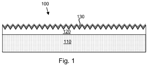
illustrated in Fig. 1, which shows a medical device 100 that comprises a
substrate 110
(e.g., a stainless steel substrate, etc.), a rough therapeutic layer 120
disposed over the
substrate 110, and a porous/pro-porous inorganic layer 130 (e.g., a PVD
iridium layer,
etc.) disposed over the therapeutic layer 120 and the substrate 110. The rough
therapeutic
layer 120 consists of at least one therapeutic agent or comprises at least one
therapeutic
agent and at least one additional material (e.g., a material that serves as a
reservoir/binder/matrix for the therapeutic agent). One specific example of a
rough
therapeutic layer is an electrosprayed SIBS/paclitaxel layer such as that
described above.
[0064] Examples of such additional materials include biostable and
biodisintegrable
organic and inorganic materials, which may be selected from those described
above,
among others. Such additional materials may thus be biodisintegrable,
biostable, or
partially biodisintegrable and partially biostable.
[0065] As another example, a composition containing at least one therapeutic
agent (e.g.,
a powder, a solution, a liquid suspension, a melt, etc.) and any optional
additional
materials (e.g., materials that serve as reservoirs/binders/matrices for the
therapeutic
agent, solvent species, etc.) may be applied to a rough substrate or to a
rough layer on a
substrate.
[0066] In some embodiments, depending on the nature of the rough substrate or
rough
layer and on the nature of the applied composition, the therapeutic agent may
be
incorporated into the rough layer or rough substrate (or at least the surface
portion of the
rough layer or rough substrate). For example, the applied composition may be
introduced
21
CA 02734494 2011-02-16
WO 2010/027678 PCT/US2009/054394
into pores that are associated with the rough substrate or rough layer. As
another
example, the applied composition may be a solution, in which the therapeutic
agent is
dissolved in a solvent system that is also a swelling agent for the material
forming the
rough substrate or rough layer. This solution may be applied to the rough
substrate or
rough layer such that the rough substrate or rough layer is swollen by the
solution,
thereby uptaking the therapeutic agent contained therein.
[0067] A structure of this type is shown is shown schematically in Fig. 2,
which shows a
medical device 100 that comprises a rough substrate 110 and a porous/pro-
porous
inorganic layer 130 disposed over the substrate 110. In the structure of Fig.
2, the
therapeutic agent, which has been introduced into to upper portion of the
rough substrate
110, is depicted by the more darkly shaded portion of the rough substrate 110.
[0068] In other embodiments, the applied composition yields a distinct
therapeutic layer
on the surface of the rough substrate or rough layer. For example, the
therapeutic layer
may consist of a single therapeutic agent (or a mixture of therapeutic agents)
in
substantially pure form (i.e., without an additional material that is not a
therapeutic
agent). As another example, the therapeutic layer may include at least one
therapeutic
agent in combination with at least one additional material (e.g., a material
that serves as a
reservoir/binder/matrix for the therapeutic agent, such as those described
above).
[0069] One example of such a medical device is schematically illustrated in
Fig. 3, which
shows a medical device 100 in accordance with an embodiment of the invention.
The
medical device shown comprises a rough substrate 110, a therapeutic layer 120
disposed
over the rough substrate 110 (specifically two therapeutic-agent-containing
regions, each
constituting a portion of a patterned therapeutic layer 120, are shown), and a
porous/pro-
porous inorganic layer 130 over the therapeutic layer 120 and the substrate
110.
[0070] Another example of such a medical device is schematically illustrated
in Fig. 4,
which shows a medical device 100 in accordance with an embodiment of the
invention.
The medical device 100 shown comprises a substrate 110, rough layer 140
disposed over
the substrate, a therapeutic layer 120 (three therapeutic-agent-containing
regions, each
constituting a portion of the therapeutic layer 120, are shown) disposed over
the rough
22
CA 02734494 2011-02-16
WO 2010/027678 PCT/US2009/054394
layer 140, and a porous/pro-porous inorganic layer 130 disposed over the
therapeutic
layer 120, rough layer 140 and the substrate 110.
[0071] As indicated above, additional materials for use in therapeutic layers
may vary
widely and include organic and inorganic materials. In certain embodiments,
the
additional materials may be selected from sol-gel derived metallic and non-
metallic
oxides. For example, at least one therapeutic agent may be, for example,
combined with
a sol or sol precursor (e.g., metal or semi-metal alkoxide solution), which is
subsequently
used to form a gel layer on a rough layer or rough substrate. Alternatively,
at least one
therapeutic agent (e.g., in the form of a solution or a suspension) may be
introduced to a
previously formed gel, in which case the gel may be subjected to elevated
temperatures
(e.g., in order to calcinate and strengthen the gel) prior to contact with the
therapeutic
agent. Such temperatures could otherwise destroy the therapeutic agent.
[0072] As previously indicated, a supplemental layer of material, for example,
a fully or
partially biodegradable organic or inorganic material layer or a porous
organic or
inorganic material layer, may be provided between the therapeutic layer and
the
porous/pro-porous inorganic layer, for example, in order to slow the release
of the
therapeutic agent. An example of such a structure is shown in Fig. 5, which is
similar to
Fig. 4, except that a supplemental layer of material 150 is disposed beneath
the
porous/pro-porous inorganic layer 130.
[0073] As noted above, in some embodiments, the porous/pro-porous inorganic
layers
described herein are advantageous in that they can act to prevent fragments of
biodegradable materials disposed under the same from escaping the device.
Moreover, in
some embodiments, the porous/pro-porous inorganic layers described herein are
advantageous in that they can shield underlying materials (e.g., a substrate
material, a
material used to form the rough layer, an additional material associated with
the
therapeutic layer, etc.) from direct contact with a subject into which the
device is
implanted. For example, an underlying material within the device may be one
that results
in thrombosis upon direct contact with the bloodstream, but which does not
cause such an
effect in the presence of an overlying porous inorganic layer.
23
CA 02734494 2011-02-16
WO 2010/027678 PCT/US2009/054394
[0074] In some aspects of the invention, the overlying inorganic layer is a
smooth pro-
porous layer. By "smooth" is meant a region whose surface roughness lies below
the
Sa values set forth above which define a "rough" surface. In many embodiments,
a
smooth surface will be glossy, in which case the surface structure has lateral
discontinuities below the optical wavelength (e.g., an Sa value below about
300 nm).
[0075] A smooth surface layer may be desirable under a variety of
circumstances. As
one example, it may be desirable to provide a smooth layer on a stent,
particularly the
luminal surface of a stent, so as to avoid the possibility of balloon damage
that may be
attendant to the presence of a rough surface layer. Moreover, because the pro-
porous
layer is not initially porous, it may act to protect the underlying
therapeutic agent from
external conditions (e.g., exposure to ethylene oxide during device
sterilization, etc.) in
certain embodiments. In some embodiments, a medical device having a porous
layer is
subjected to a sterilization cycle prior to loading the porous layer with a
therapeutic agent,
after which the therapeutic-agent-loaded layer is closed off by an additional
layer (e.g., a
biodisintegrable layer or a pro-porous layer, which may be further subjected
to an
additional sterilization step).
[0076] In certain embodiments, the pro-porous layer has a configuration that
allows the
electropolishing of the layer to achieve a smooth surface. For example, the
outermost
surface of a porous or pro-porous layer may be covered in a biodegradable
metal (e.g.,
magnesium or a magnesium alloy), which is then electropolished. The magnesium
surface
then biodisintegrates in vivo, allowing release the agent. Where immediate
release of
therapeutic agent is required, certain portions of the biodegradable metal may
be etched
away (while protecting/masking the smooth surfaces), followed by therapeutic
agent
loading in certain embodiments.
[0077] Pro-porous layers in accordance with the invention may comprise, for
example,
both biodisintegrable and biostable phases. Upon placement in vivo, the device
ultimately develops pores, allowing the therapeutic agent to be released. In
the case of a
stent or another vascular medical device, the development of porosity may
promote
endothelial cell growth. In this regard, submicron topography, including
pores, fibers,
and elevations in the sub-100 nm range, has been observed for the basement
membrane of
24
CA 02734494 2011-02-16
WO 2010/027678 PCT/US2009/054394
the aortic valve endothelium as well as for other basement membrane materials.
See R.G.
Flemming et al., Biomaterials 20 (1999) 573-588, S. Brody et al., Tissue Eng.
2006 Feb;
12(2): 413-421, and S.L. Goodman et al., Biomaterials 1996; 17: 2087-95.
Goodman et
al. employed polymer casting to replicate the topographical features of the
subendothelial
extracellular matrix surface of denuded and distended blood vessels, and they
found that
endothelial cells grown on such materials spread faster and appeared more like
cells in
their native arteries than did cells grown on untextured surfaces.
[0078] An example of a device having a smooth pro-porous layer is
schematically
illustrated in Fig. 6A. A medical device 100 is shown, which comprises a rough
substrate
110 (e.g., a stainless steel substrate roughened by a PIII process, etc.), a
therapeutic layer
120 (e.g., a layer of pure therapeutic agent such as a layer of paclitaxel or
everolimus,
etc.) disposed within the crevasses of the rough substrate 110, and a smooth
pro-porous
inorganic layer 130 (e.g., a layer comprising a biostable metallic phase such
as an iridium
phase, shown in light grey, and a biodisintegrable metallic phase such as a
magnesium
phase, shown in dark grey) disposed over the therapeutic layer 120 and rough
substrate
110. As discussed below, such a layer 130 may be formed via PVD using a mixed
composition target. Upon insertion of the device 100 into a subject, at least
a portion of
the biodisintegrable metallic phase is removed, leaving behind a porous layer
130p as
shown in Fig. 6B, allowing the release of the therapeutic agent from the
device.
[0079] As indicated above, in some embodiments, an additional material may be
admixed
with the therapeutic agent in the therapeutic layer and/or a supplemental
layer may be
disposed over the therapeutic layer. In these embodiments release profile of
the
therapeutic agent may be dictated by the pro-porous inorganic layer and by the
additional
material and/or supplemental layer. Moreover, the pro-porous inorganic layer
can act as a
barrier that prevents fragments of any underlying biodisintegrable materials
from being
released from the device.
[0080] In certain embodiments, the therapeutic agent is provided within
surface
depressions in the substrate. For example, a medical device 100 is illustrated
schematically in Fig. 7A, which comprises a substrate 110 and a therapeutic
layer 120
disposed within a series of depressions within the substrate 110. A smooth pro-
porous
CA 02734494 2011-02-16
WO 2010/027678 PCT/US2009/054394
inorganic layer 130 (e.g., like that described above in connection with Fig.
6A) is
disposed over the therapeutic layer 120 and substrate 110. As with the device
of Fig. 6A,
upon insertion of the device into a subject, a porous layer 130p is formed in
vivo as
shown in Fig. 7B, allowing the release of the therapeutic agent from the
device.
[0081] Examples of depressions include trenches, blind holes and pores, among
others.
Depressions may be created in a great variety of shapes and sizes. Multiple
depressions
can be provided in a near infinite variety of arrays. Examples of blind holes
include those
whose lateral dimensions at the surface are circular, polygonal (e.g.,
triangular,
quadrilateral, penta-lateral, etc.), as well as blind holes of various other
regular and
irregular shapes and sizes. Trenches include simple linear trenches, wavy
trenches,
trenches formed from linear segments whose direction undergoes an angular
change (e.g.,
zigzag trenches), and linear trench networks intersecting various angles, as
well as other
regular and irregular trench configurations. The depressions can be of any
suitable size.
For example, the medical devices of the invention typically contain
depressions whose
smallest lateral dimension (e.g., the width) is less than 10 mm (10000 pm),
for example,
ranging from 10000 pm to 1000 pm to 100 pm to 10 pm to 1 pm to 100 nm or less.
[0082] Examples of techniques for forming depressions (e.g., pores, blind
holes, trenches,
etc.) include methods in which a material contains depressions as-formed.
These include
molding techniques in which a mold may be provided with various protrusions,
which
after casting the substrate of interest, create depressions in the material.
These techniques
further include techniques, such as foam-based techniques, whereby a porous
material is
formed. Porous materials may also be formed by removing one component from a
multi-
component material using a suitable process (e.g., dissolution, etching,
etc.). Examples
of techniques for forming depressions further include direct removal
techniques as well as
mask-based removal techniques, in which masking is used to protect material
that is not
to be removed. Direct removal techniques include those in which material is
removed
through contact with solid tools (e.g., microdrilling, micromachining, etc.)
and those that
remove material without the need for solid tools (e.g., those based on
directed energetic
beams such as laser, electron, and ion beams). Mask-based techniques include
those in
which the masking material contacts the material to be machined (e.g., where
masks are
26
CA 02734494 2011-02-16
WO 2010/027678 PCT/US2009/054394
formed using known lithographic techniques) and techniques in which the
masking
material does not contact the material to be machined, but which is provided
between a
directed source of excavating energy and the material to be machined (e.g.,
opaque masks
having apertures formed therein, as well as semi-transparent masks such as
gray-scale
masks which provide variable beam intensity and thus variable machining
rates).
Material is removed in regions not protected by the above masks using any of a
range of
processes including physical processes (e.g., thermal sublimation and/or
vaporization of
the material that is removed), chemical processes (e.g., chemical breakdown
and/or
reaction of the material that is removed), or a combination of both. Specific
examples of
removal processes include wet and dry (plasma) etching techniques, and
ablation
techniques based on directed energetic beams such as electron, ion and laser
beams. In
still other embodiments, depressions may be formed by selective growth of a
material on
a substrate surface, for example, on a patterned surface or on a masked
surface.
[0083] Various methods for forming porous and pro-porous inorganic layers will
now be
described. For example, in some embodiments, the layers may be formed via
vapor
deposition methods, including physical vapor deposition (PVD) techniques. PVD
processes are processes in which a source of material, typically a solid
material, is
vaporized, and transported to a structure upon which a film (i.e., a layer) of
the material is
formed. In the present invention, the solid material may be, for example, a
biodisintegrable inorganic material, biostable inorganic material, or a
combination of
biodisintegrable and biostable inorganic materials.
[0084] PVD processes are generally used to deposit films with thicknesses in
the range of
a few nanometers to thousands of nanometers, although greater thicknesses are
possible.
PVD is typically carried out under vacuum (i.e., at pressures that are less
than ambient
atmospheric pressure). In many embodiments, the pressure associated with PVD
techniques is sufficiently low such that little or no collisions occur between
the vaporized
source material and ambient gas molecules while traveling to the substrate.
Hence, the
trajectory of the vapor is generally a straight (line-of-sight) trajectory.
[0085] In certain embodiments, the PVD processing parameters are selected to
form a
porous layer. For example, as noted above, where line-of-sight processes such
as PVD-
27
CA 02734494 2011-02-16
WO 2010/027678 PCT/US2009/054394
based processes are employed in the formation of an inorganic layer over a
rough
underlying material, the roughness of the underlying material can lead to
incomplete
coverage of the underlying material and the creation of a porous inorganic
layer. This is
shown schematically in Figs. l0A-lOB. Fig IOA is an illustration of a medical
device
100 comprising a substrate 110 and a rough therapeutic layer 120, for example,
a layer of
partially fused polymeric particles that act as a matrix for a therapeutic
agent (e.g.,
electrosprayed SIBS/paclitaxel, etc.). As shown in Fig. 10B, PVD-based
deposition of
an inorganic layer 130 (e.g., an iridium layer, etc.) results in substantial,
but incomplete,
coverage of the therapeutic layer 120 such that the inorganic layer 130 is
porous. (On the
other hand, if deposition is continued long enough, a smooth, thick non-porous
inorganic
layer will ultimately be formed.)
[0086] In other embodiments, the PVD processing parameters are selected to
form a pro-
porous layer. For example, a biostable metal and a biodisintegrable metal may
be co-
deposited such that a layer is formed with distinct biostable and
biodisintegrable metal
phases, whose phase morphology is such that a porous layer is formed upon
biodisintegration and removal of the biodisintegrable metal phase in vivo.
[0087] Some specific PVD methods that are used to form porous/pro-porous
layers in
accordance with the present invention include evaporation, sublimation,
sputter
deposition and laser ablation deposition. For instance, in some embodiments,
at least one
source material is evaporated or sublimed, and the resultant vapor travels
from the source
to a substrate, resulting in a deposited layer on the substrate. Examples of
sources for
these processes include resistively heated sources, heated boats and heated
crucibles,
among others. Sputter deposition is another PVD process, in which surface
atoms or
molecules are physically ejected from a surface by bombarding the surface
(commonly
known as a "target") with high-energy ions. Ions for sputtering can be
produced using a
variety of techniques, including arc formation (e.g., diode sputtering),
transverse
magnetic fields (e.g., magnetron sputtering), and extraction from glow
discharges (e.g.,
ion beam sputtering), among others.
[0088] Pulsed laser deposition (PLD) is yet another PVD process, which is
similar to
sputter deposition, except that vaporized material is produced by directing
laser radiation
28
CA 02734494 2011-02-16
WO 2010/027678 PCT/US2009/054394
(e.g., pulsed laser radiation), rather than high-energy ions, onto the target
material. As
advantage of the PLD process is that films can be deposited upon substrates at
or near
room. Consequently, films can be formed over temperature-sensitive materials,
for
example, organic materials such as polymers and therapeutic agents.
[0089] In a typical PLD process, and with reference to the schematic
illustration of Fig. 8,
a laser pulse 810 is directed into a vacuum chamber 850 through a window 850w
and
impinges onto a target material 820 to be deposited. The laser pulse 810
vaporizes the
target material 820, forming a plume 830 that contains various species (e.g.,
neutral,
ionic, molecular, etc.). These species travel toward a substrate, in this
case, a rotating
stent 800, and are deposited on the stent 800 in the form of a thin film. (If
desired, the
stent 800 may also be reciprocated longitudinally to improve coverage.)
Targets include
targets formed from a single material (e.g., a single metal or metal oxide)
and targets
formed from a multiple materials (e.g., multiple metals or multiple metal
oxides). For
example, the target 820 shown in Fig. 8 is a rotating target that comprises
two materials,
magnesium 820m and iridium 820i. Consequently, the film deposited on the
rotating
stent 800 contains magnesium and iridium. When the magnesium is removed upon
implantation in a subject, a porous iridium layer is formed, as previously
described.
[0090] As an alternative to an apparatus like that of Fig. 8, a dual beam set-
up for
simultaneous Mg/Ir deposition may be used, in which a first beam strikes an Mg
target or
an Mg region of a Mg-Ir composite target and a second beam strikes an Ir
target or an Ir
region of a composite target. This leads to a simultaneous deposition of both
materials
with layer thickness and composition depending on laser intensity per spot,
distance to
substrate, material type, and so forth.
[0091] As noted above, in certain embodiments, porous and pro-porous inorganic
layers
are formed from inorganic particles, which may be, for example,
biodisintegrable
inorganic particles, biostable inorganic particles, or a combination of
biodisintegrable and
biostable inorganic particles. In some embodiments at least some of the
particles have the
same composition as the underlying medical device substrate. Specific examples
include
iridium, tantalum, titanium, cobalt, iron, zinc, gold, alloys containing two
or more of the
same, stainless steel and nitinol.
29
CA 02734494 2011-02-16
WO 2010/027678 PCT/US2009/054394
[0092] Methods of forming porous/pro-porous inorganic layers in accordance
with the
present invention include those wherein inorganic nanoparticles are created,
accelerated
and directed onto upper surfaces of structures, thereby forming inorganic
layers over the
structures. For example, in some embodiments, the nanoparticles are charged
nanoparticles, which are accelerated onto a structure surface by subjecting
them to an
electric field. The trajectory of the nanoparticles may be further influenced
through the
use of a secondary electric field or a magnetic field, where desired. In some
embodiments, the nanoparticles are magnetic or ferromagnetic nanoparticles,
which are
accelerated onto a structure surface by subjecting them to a suitable magnetic
field. The
trajectory of the nanoparticles may be further influenced through the use of a
secondary
magnetic field, where desired.
[0093] Without wishing to be bound by theory, when nanoparticles are
accelerated
towards a surface (e.g., in a magnetic field, electrical field, etc.), melting
can be induced
upon landing by imparting them with sufficient kinetic energy. As seen from
the above,
there are various ways to accelerate nanoparticles toward a structure. For
example, in
embodiments where charged nanoparticles are accelerated using an electric
field, a low
applied voltage will create a small electric field which lands them on the
substrate with
little or no thermal effects. Higher applied voltages, however, will result in
greater field
strengths, which if sufficiently great will result in a transformation of
kinetic energy into
heat in an amount sufficient to melt the nanoparticles slightly together,
leaving gaps
between the particles. Similarly, in embodiments where magnetic or
paramagnetic
nanoparticles are accelerated using a magnetic field, a low magnetic field
strength will
just land the nanoparticles on the surface with little or no thermal effects,
whereas higher
magnetic field strengths will result in the transformation of kinetic energy
into heat
sufficient to melt the nanoparticles slightly together, leaving gaps between
the particles.
Even higher field strengths (e.g., magnetic, electrical, etc.) will solidify
the individual
particles into a solid material without gaps. In some embodiments, adhesion of
the
nanoparticles to the underlying structure and/or to one another each other can
be tuned
(e.g., by the extent of acceleration). Moreover, layers can be formed, which
are tough
and adherent or soft and friable.
CA 02734494 2011-02-16
WO 2010/027678 PCT/US2009/054394
[0094] Where porous inorganic layers are formed, the size distribution of the
nanoparticles may have a large effect on the pore-size distribution, with
larger particles
capable of creating larger pores, which pore sizes may be further tailored
through the
adjustment of field strength. Sustained drug release may be promoted by
creating a
uniform porosity throughout the nanoporous layer, which will depend upon both
the
initial size of the particles as well as upon the melting effect that arises
from the field
strength.
[0095] As a specific example, a system for performing nanoparticle deposition
along the
lines described above is available from Mantis Deposition Ltd., Thame,
Oxfordshire,
United Kingdom, who market a high-pressure magnetron sputtering source which
is able
to generate nanoparticles from a sputter target with as few as 30 atoms up to
those with
diameters exceeding 15 nm. (A system similar to the Mantis system can be
obtained from
Oxford Applied Research, Witney, Oxon, UK.) This system is operated at about
5x10⁻⁵
mbar, although the precise operating pressure used will vary widely, depending
on the
specific process and system that is employed, among other factors. The size of
the
nanoparticles is affected by several parameters, including the nanoparticle
material, the
distance between the magnetron surface and the exit aperture (e.g., larger
distances have
been observed to create larger nanoparticles), gas flow (e.g., higher gas
flows have been
observed to create smaller nanoparticle sizes), and gas type (e.g., helium has
been
observed to produce smaller particles than argon). For a particular setting,
the size
distribution can be measured using a linear quadrapole device placed after the
exit
aperture of the magnetron chamber. The quadrapole device can also be used in-
line to
select a narrow nanoparticle size range for deposition. Systems like the
Mantis Deposition
Ltd. system can produce nanoparticles, a large fraction of which of which
(approximately
40% to 80%) have a charge of one electron. Consequently, a magnetic field or a
secondary electric field can be used to separate particles of similar weight
from one
another (because lighter particles are deflected to a greater degree in a
given field than are
the larger particles of the same charge). For example, the above Mantis
Deposition Ltd.
system is able to produce charged nanoparticle streams with a very narrow mass
distribution. Moreover, it is possible to accelerate the negatively charged
particles onto a
positively biased surface in order to impact the particles on the surface with
elevated
31
CA 02734494 2011-02-16
WO 2010/027678 PCT/US2009/054394
kinetic energy. A positively biased grid may also be used to accelerate the
particles,
allowing the particles to pass through holes in the grid and impinge on the
surface. By
altering the bias voltage from low to high values the deposited film changes
from porous
loosely bound nanoparticles to a solid film of metal. Due to the fact that the
amount of
energy needed to melt the individual nanoparticles is relatively low compared
to the
energy needed to increase the bulk temperature of an underlying structure,
this process is
effectively performed at or near room temperature. When using a system like
the Mantis
Deposition Ltd. system, it has been found that the bias voltage (which may
vary, for
example, from 10 V to 5000 V) and the particle size (which may vary, for
example, from
0.7 nm to 25 nm) has a significant effect upon drug release, with higher
voltages and
smaller particle sizes yielding coatings with reduced drug release.
[0096] As previously indicated, in some PVD embodiments, it may be desirable
to
change the orientation of the structure (upon which the material is to be
deposited)
relative to the material stream. For example, a tubular medical device such as
a stent may
be axially rotated (and, optionally, reciprocated longitudinally) while
exposing it to the
material stream.
EXAMPLE
[0097] A Nitinol drug eluting spiral is made for an application in the
superior femoral
artery (SFA). Specifically, a 2130 mm long, 0.30 mm nitinol wire (type S),
Memory
Metalle GmbH, Am Kesselhaus 5, D-79576 Weil am Rhein, Germany, is shape set
into a
spiral shape (diameter 4.5 mm, pitch 2 mm at a temperature of 475 C over the
course of 5
minutes).
[0098] An electrospun fiber network of polymer nano-fibers is formed on the
Nitinol
surface, after which the fiber network is covered by an everolimus coating,
and a final
coating layer of TiOX (titania) particles, leaving a porous titiania membrane
around the
everolimus-coated PEI fibers. The internal PEI fiber network serves both as
surface
enlarger as well as scaffolding to hold the titania layer intact.
[0099] More particularly, polyetherimide (PEI) from Aldrich Co. (St. Louis,
Mo.), and
BiopolTM polyhydroxybutyrate-valerate (PHBV) from Monsanto Company (St. Louis,
32
CA 02734494 2011-02-16
WO 2010/027678 PCT/US2009/054394
Mo.) are mixed in chloroform making respective solutions having 23 wt% PEI and
21
wt% PHBV. These two solutions are mixed to a ratio of 75/25 (PEI/PHBV) . The
Nitinol
spiral is stretched vertically to at or near its full original 2130 mm length
using a 500 g
weight, and a grounded electrical contact is connected to each end of the
stretched wire.
A nozzle with a syringe is placed at a distance of 15 cm from the Nitinol wire
and
connected to a syringe pump (type SP 101i, World Precision Instruments,
Liegnitzer
Str. 15, D-10999 Berlin, Germany) and a high voltage supply (Type CS209 1,
High
Voltage Power Solutions, Inc., Dallas, Tex.). The Nitinol wire is rotated at 5
Hz during
the spraying process and moved along the axis in a cyclic movement of 12 Hz
with an
amplitude of 2 mm up and 2.5 mm down. The spraying is carried out at the
following
settings: 15 kV, 0.05 ml/min, 6 minutes for one cycle. The wire sprayed in
this way is
thermally treated for 90 minutes at 210 C. in a nitrogen environment to
decompose the
PHBV component and leave behind a fiber meshwork made of porous PEI fibers on
the
Nitinol wire. The weight is removed from the wire during the drying process to
allow the
wire to return to its spiral shape.
[0100] In the following step, this fiber PEI network is covered with an
Everolimus
coating by dissolving Everolimus 2% by weight in a 50:50 mixture of
cyclohexanone and
acetone. This solution is sprayed onto the porous PEI fibers covering the
Nitinol spiral.
During the spraying process at a rate of 0.05 mL/min (same syringe pump as
above), the
Nitinol wire is rotated at 5 Hz and moved up at a speed of 50 cm/minute in
order to
obtain an everolimus dose of about 100ug/cm2 of covered vessel wall after
implantation.
[0101] In order to cover the entire assembly with a layer of TiOX
nanoparticles (which
may also include heparin), an aqueous solution containing 0.01 mol/L of
titanium
tetrachloride and 0.1 mol/L of hydrochloric acid is prepared. Titanium (IV)
chloride is
added under vigorous stirring to the aqueous solution. The aqueous solution is
poured into
a microwave reactor (Biotage Advancer, Biotage, Uppsala, Sweden), a 0.4-MPa
argon
pressure is introduced into the system, and then the reactor is exposed to
microwaves for
30 s at 500 Watt power level. The pressure level is maintained at a max of 1.5
bar. An
aqueous heparin solution (200 mg/10 ml water) is prepared and added under
vigorous
stirring to the resulting TiOX solution in a 1:1 ratio immediately after the
TiOX solution is
33
CA 02734494 2011-02-16
WO 2010/027678 PCT/US2009/054394
cooled to room temperature. The Nitinol-supported spiral is dip-coated 4 times
in the
heparin\TiOX solution and dried in between dip-coating steps at 70 C for 1
hour.
[0102] Although various embodiments are specifically illustrated and described
herein, it
will be appreciated that modifications and variations of the present invention
are covered
by the above teachings and are within the purview of the appended claims
without
departing from the spirit and intended scope of the invention.
34