Note: Descriptions are shown in the official language in which they were submitted.
CA 02734501 2011-02-16
WO 2010/027888 PCT/US2009/055128
-1-
ULTRASONIC SURGICAL BLADE
Cross Reference to Related Applications
[0001] This present application claims the benefit of U.S. Provisional
application, serial no.
61/093,836, filed on September 3, 2008, the contents of which are incorporated
by
reference herein.
Statement Re2ardin2 Federally Sponsored Research or Development
[0002] Not Applicable.
Field of the Invention
[0003] The various embodiments relate, in general, to ultrasonic surgical
blades for use in
surgical instruments and, more particularly, to an ultrasonic surgical blade
with improved
cutting and coagulation features.
Background of the Invention
[0004] Ultrasonic instruments, including both hollow core and solid core
instruments, are used
for the safe and effective treatment of many medical conditions. Ultrasonic
instruments,
and particularly solid core ultrasonic instruments, are advantageous because
they may be
used to cut and/or coagulate organic tissue using energy in the form of
mechanical
vibrations transmitted to a surgical end effector at ultrasonic frequencies.
Ultrasonic
vibrations, when transmitted to organic tissue at suitable energy levels and
using a
suitable end effector, may be used to cut, dissect, elevate or cauterize
tissue or to separate
muscle tissue off bone. Ultrasonic instruments utilizing solid core technology
are
particularly advantageous because of the amount of ultrasonic energy that may
be
transmitted from the ultrasonic transducer, through a waveguide, to the
surgical end
CA 02734501 2011-02-16
WO 2010/027888 PCT/US2009/055128
-2-
effector. Such instruments may be used for open procedures or minimally
invasive
procedures, such as endoscopic or laparoscopic procedures, wherein the end
effector is
passed through a trocar to reach the surgical site.
[0005] Activating or exciting the end effector (e.g., cutting blade) of such
instruments at
ultrasonic frequencies induces longitudinal vibratory movement that generates
localized
heat within adjacent tissue, facilitating both cutting and coagulation.
Because of the
nature of ultrasonic instruments, a particular ultrasonically actuated end
effector may be
designed to perform numerous functions, including, for example, cutting and
coagulation.
[0006] Ultrasonic vibration is induced in the surgical end effector by
electrically exciting a
transducer, for example. The transducer may be constructed of one or more
piezoelectric
or magnetostrictive elements in the instrument hand piece. Vibrations
generated by the
transducer section are transmitted to the surgical end effector via an
ultrasonic waveguide
extending from the transducer section to the surgical end effector. The
waveguides and
end effectors are designed to resonate at the same frequency as the
transducer. Therefore,
when an end effector is attached to a transducer the overall system frequency
is the same
frequency as the transducer itself.
[0007] The shape of an ultrasonic surgical blade or end-effector used in an
ultrasonic surgical
instrument can define at least four important aspects of the instrument. These
are: (1) the
visibility of the end-effector and its relative position in the surgical
field, (2) the ability of
the end-effector to access or approach targeted tissue, (3) the manner in
which ultrasonic
energy is coupled to tissue for cutting and coagulation, and (4) the manner in
which tissue
can be manipulated with the ultrasonically inactive end-effector. It would be
advantageous to provide an improved ultrasonic surgical instrument blade or
end-effector
optimizing at least these four aspects of the instrument.
[0008] Solid core ultrasonic surgical instruments may be divided into two
types, single element
end effector devices and multiple-element end effector. Single element end
effector
devices include instruments such as scalpels, and ball coagulators. Single-
element end
CA 02734501 2011-02-16
WO 2010/027888 PCT/US2009/055128
-3-
effector instruments have limited ability to apply blade-to-tissue pressure
when the tissue
is soft and loosely supported. Substantial pressure may be necessary to
effectively couple
ultrasonic energy to the tissue. This inability to grasp the tissue results in
a further
inability to fully coapt tissue surfaces while applying ultrasonic energy,
leading to less-
than-desired hemostasis and tissue joining. The use of multiple-element end
effectors
such as clamping coagulators includes a mechanism to press tissue against an
ultrasonic
blade that can overcome these deficiencies.
[0009] Ultrasonic clamp coagulators provide an improved ultrasonic surgical
instrument for
cutting/coagulating tissue, particularly loose and unsupported tissue, wherein
the
ultrasonic blade is employed in conjunction with a clamp for applying a
compressive or
biasing force to the tissue, whereby faster coagulation and cutting of the
tissue, with less
attenuation of blade motion, are achieved.
[0010] Current ultrasonic blade designs are optimized for soft tissues. The
current blade designs,
in the presence of a continuum of soft tissue, such as viscera, to tough
tissue, such as
cartiledge, preferentially cut the soft tissues. When the blade hits harder or
tougher tissue,
the blade tends to deflect away from such tissue and continue along the path
of least
resistance. This performance is often preferred for dissecting between planes
of tissue,
but makes it difficult to cut tough tissue, such as cartilage.
[0011] Consequently, a significant need exists for an ultrasonic blade that is
able to cut different
tissue types. The present invention provides for such an ultrasonic device.
Brief Description of the Figures
[0012] The novel features of the invention are set forth with particularity in
the appended claims.
The invention itself, however, both as to organization and methods of
operation, may
best be understood by reference to the following description, taken in
conjunction with
the accompanying drawings in which:
[0013] FIGURE 1 illustrates one embodiment of an ultrasonic surgical system;
CA 02734501 2011-02-16
WO 2010/027888 PCT/US2009/055128
-4-
[0014] FIGURE 2 is a perspective view of a prior art ultrasonic blade;
[0015] FIGURE 3 is a perspective view of one embodiment of the present
invention;
[0016] FIGURE 4 is a perspective view of an alternate expression of on
embodiment of the
present invention;
[0017] FIGURE 5 is an elevation and partial cut away view of one expression of
an embodiment
of the invention;
[0018] FIGURE 6 is an elevation and partial cut away view of an alternate
expression of an
embodiment of the invention;
[0019] FIGURE 7 is an elevation and partial cut away view of an alternate
expression of an
embodiment of the invention;
[0020] FIGURE 8 is a partial plan view of an alternate expression of an
embodiment of the
invention;
[0021] FIGURE 9 is a perspective view of an alternate embodiment of the
invention illustrating
proximal serrations;
[0022] FIGURE 10 is a plan view of an alternate embodiment of the invention;
and
[0023] FIGURE 11 s a plan view of an alternate embodiment of the invention.
Detailed Description of the Invention
[0024] Before explaining the present invention in detail, it should be noted
that the embodiments
are not limited in its application or use to the details of construction and
arrangement of
parts illustrated in the accompanying drawings and description. The
illustrative
embodiments may be implemented or incorporated in other embodiments,
variations and
modifications, and may be practiced or carried out in various ways. For
example, the
surgical instruments and blade configurations disclosed below are illustrative
only and
not meant to limit the scope or application thereof. Further, unless otherwise
indicated,
CA 02734501 2011-02-16
WO 2010/027888 PCT/US2009/055128
-5-
the terms and expressions employed herein have been chosen for the purpose of
describing the illustrative embodiments for the convenience of the reader and
are not to
limit the scope thereof.
[0025] The various embodiments relate, in general, to ultrasonic surgical
blades for use in
surgical instruments and, more particularly, to an ultrasonic surgical blade
with improved
cutting and coagulation features. A blade according to various embodiments is
of
particular benefit, among others, in orthopedic procedures wherein it is
desirable to
remove tough tissue, such as cartilage, and/or tissue while controlling
bleeding for
removing muscle tissue from bone, due to its cutting and coagulation
characteristics. A
blade according to the various embodiments may reduce the user force required
to
remove muscle from bone and, in one embodiment, may be useful to
simultaneously
hemostatically seal or cauterize the tissue. Reducing the force to operate the
surgical
instrument may reduce user fatigue, improve precision and reduce unwanted
tissue
damage.
[0026] The blade, however, may also be useful for general soft tissue cutting
and coagulation,
for example in plastic surgeries, such as breast augmentation or reduction.
Soft tissues
are often difficult for the surgeon to suspend and tension so that ultrasonic
tool pressure
can be effectively applied to achieve efficient cutting action. The various
embodiments of
the invention allow the surgeon to capture and effectively tension the tissue
against the
cutting edges of the blade.
[0027] A blade according to various embodiments may be useful in spine
surgery, especially to
assist in posterior access in removing muscle from bone. A variety of
different blade
configurations are disclosed which may be useful for both open and
laparoscopic
applications.
[0028] Examples of ultrasonic surgical instruments are disclosed in U.S. Pat.
Nos. 5,322,055 and
5,954,736 and in combination with ultrasonic blades and surgical instruments
disclosed
in U.S. Pat. Nos. 6,278,218B1, 6,283,981 B1, 6,309,400 B2, 6,325,811 B1 and
6,423,082
CA 02734501 2011-02-16
WO 2010/027888 PCT/US2009/055128
-6-
B1, for example, and commonly-owned, co-pending U.S. Patent Applications
Serial No.
11/726,625, entitled Ultrasonic Surgical Instruments, filed on March 22, 2007
and Serial
No. 11/998,543, entitled Ultrasonic Surgical Instrument Blades, filed on
November 30,
2007.
[0029] Certain exemplary embodiments will now be described to provide an
overall
understanding of the principles of the structure, function, manufacture, and
use of the
devices and methods disclosed herein. One or more examples of these
embodiments are
illustrated in the accompanying drawings. Those of ordinary skill in the art
will
understand that the devices and methods specifically described herein and
illustrated in
the accompanying drawings are non-limiting exemplary embodiments and that the
scope
of the various embodiments is defined solely by the claims. Further, it is
understood that
any one or more of the following-described embodiments, expressions of
embodiments,
examples, etc. can be combined with any one or more of the other following-
described
embodiments, expressions of embodiments, examples, etc. Such modifications and
variations are intended to be included within the scope of the claims.
[0030] Fig. 1 illustrates one representative embodiment of an ultrasonic
system 10. One
embodiment of the ultrasonic system 10 comprises an ultrasonic signal
generator 12
coupled to an ultrasonic transducer 14, a hand piece assembly 60 comprising a
hand piece
housing 16, and an end effector 50. The ultrasonic transducer 14, which is
known as a
"Langevin stack", generally includes a transduction portion 18, a first
resonator or end-
bell 20, and a second resonator or fore-bell 22, and ancillary components. The
ultrasonic
transducer 14 is preferably an integral number of one-half system wavelengths
(nXJ2) in
length as will be described in more detail later. An acoustic assembly 24
includes the
ultrasonic transducer 14, a mount 26, a velocity transformer 28, and a surface
30. The
construction of such an ultrasonic system 10 is well documented in at least
the references
previously incorporated by reference and well known to one skilled in the art
so its
details will be left to such documentation and will not be expanded upon here.
CA 02734501 2011-02-16
WO 2010/027888 PCT/US2009/055128
-7-
[0031] It will be appreciated that the terms "proximal" and "distal" are used
herein with
reference to a clinician gripping the hand piece assembly 60. Thus, the end
effector 50 is
distal with respect to the more proximal hand piece assembly 60. It will be
further
appreciated that, for convenience and clarity, spatial terms such as "top" and
"bottom"
also are used herein with respect to the clinician gripping the hand piece
assembly 60.
However, surgical instruments are used in many orientations and positions, and
these
terms are not intended to be limiting and absolute.
[0032] With reference to FIG 2, the invention will be described in accordance
with the ultrasonic
blade disclosed in U.S. Patent No. 6,423,082 B1 as exemplary only, and is not
intending
to be limiting and absolute. U.S. Patent 6,423,082 discloses an ultrasonic
surgical blade
110 including a top surface, a bottom surface and a cutting-edge 136. Blade
110 is a
balanced curve blade wherein its longitudinal motion is greater than 97% of
its overall
motion (including transverse motion). The cutting-edge 136 is defined by a
cutting-
surface intermediate the top surface and the bottom surface, and the top
surface has a
width greater than the width of the bottom surface. The blade may be straight
or curved.
In one embodiment of the invention, at least a portion of the cutting-surface
is
substantially parallel to at least a portion of the top surface. In still
another embodiment
of the invention first and second side-walls intersect the top surface to form
first and
second cutting-edges that may be sharp or blunt. Alternately, a second cutting-
edge 138
may be defined by a second cutting surface intermediate the top and bottom
surfaces.
Depending on the angle between the intermediate cutting-surface and the top
surface, the
cutting-edge may be sharp or blunt.
[0033] With reference to Fig. 3, shown is a first expression of a first
embodiment of the current
invention. The prior art blade of Fig. 2 is modified to present a plurality of
sharp points
140 on sharp edge 136. Sharp points 140 create high pressure contact points
with the
tissue as the blade is pressed into or against the tissue. Sharp points 140
are defined by a
cut radius, which in turn determine the spacing between adjacent sharp points.
A small
cut radius defines more sharp points 140 within a given distance and a larger
cut radius
CA 02734501 2011-02-16
WO 2010/027888 PCT/US2009/055128
-8-
defines fewer sharp points 140 within a given distance. The cut radius may
vary from
about 0.010 inches to about 0.060 inches. Alternatively, the cut radius may
vary from
one sharp point 140 to another.
[0034] Sharp points 140 initiate the dissection line allowing the user to cut
with precision
regardless of the tissue type. Sharp points 140 may exist on one sharp edge
136, or,
alternatively, sharp points 140 may exist on both sharp edges 136 and 138.
Further, sharp
points 140 are shown at the distal end of ultrasonic surgical blade 110;
however, blade
110 may be modified to include sharp points 140 at the proximal end or mid
section of
sharp edge 136 and/or 138. Further, sharp points 140 may exist along the
entire length of
sharp edge 136 and/or 138.
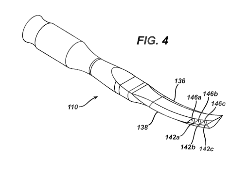
[0035] Referring now to Figs. 4-7, shown is a second expression of the first
embodiment of the
invention. Shown are sharp points 142a-c in conjunction with beveled cutting
edges 146a-c. Beveled cutting edges are defined by the angle of the bevel
relative to the
normal of blade 110 and the cut radius of the bevel. As would be appreciated
by those
skilled in the art, the bevel angle may be from greater than 0 to 90 . The
embodiment of
Fig. 3 illustrate sharp points without a bevel, therefore, the bevel angle is
0 . Preferably,
in this expression of the embodiment, the bevel angle is from about 35 to
about 50 and
more preferably, 40 . The cut radius may vary from between about 0.010 inches
to about
0.060 inches, and more preferably from about 0.020 inches to about 0.050
inches.
[0036] As shown in Fig. 4, sharp point 142a is common between bevel cutting
edges 146a and
146b; sharp point 142b is common between bevel cutting edges 146b and 146c;
and sharp
point 142c is common only to bevel cutting edge 146c. Bevel cutting edges 146a-
c may
exist on one sharp edge 136, or, alternatively, bevel cutting edges 146a-c may
exist on
both sharp edges 136 and 138. Further, bevel cutting edges 146a-c are shown at
the distal
end of ultrasonic surgical blade 110; however, blade 110 may be modified to
include
bevel cutting edges 146a-c at the proximal end or mid section of sharp edge
136 and/or
138. Further, bevel cutting edges 146a-c may exist along the entire length of
sharp edge
CA 02734501 2011-02-16
WO 2010/027888 PCT/US2009/055128
-9-
136 and/or 138. Further, the quantity of sharp points 142a-c and bevel cutting
edges
146a-c are shown for illustrative purposes only, and is not intended to be
limit in any
fashion the scope of the invention. Unexpectedly, the inventor found enhanced
performance of a blade comprising both sharp points and beveled cutting edges
for
cutting both soft and tough tissue. These blades showed enhanced cutting
efficiency with
respect to blades that were identical, but lacked the sharp points and the
bevels. In soft
tissues, such as fat and skin, the sharp points and/or the bevel features
enable application
of tension directly to the tissue via the blade geometry, rather than relying
solely on
secondary tensioning of the tissue. In cartilage, the points allowed the blade
to initiate the
incision and the beveled edges to complete the cut.
[0037] In an alternate expression of the current expression, sharp points 142a-
c and bevel cutting
edges 146a-c have a hardened surface coating. Such a coating may be that as
disclosed in
commonly-owned, co-pending U.S. Provisional Patent application, entitled
Ultrasonic
Surgical Blades, filed on November 30, 2007 as serial no. 61/004,961, the
contents of
which are incorporated by reference herein, in its entirety.
[0038] Referring now to Fig. 8, shown is a third expression of the first
embodiment, where
beveled cutting edges do not share a sharp point, but rather, beveled cutting
edges 148a-c
are separated by a cutting edge distance 150a-b. Cutting edge distance 150a-b
varies
depending upon the application, but in one exemplary embodiment, cutting edge
distance
150a-c is from about 0.001 inches to about 0.10 inches. Further, cutting edge
distance
150a-c do not have to be constant, and may vary in distance.
[0039] Beveled cutting edges 148a-c and cutting edge distance 150a-b may exist
on one sharp
edge 136, or, alternatively, beveled cutting edges 148a-c and cutting edge
distance 150a-c
may exist on both sharp edges 136 and 138. Further, beveled cutting edges 148a-
c and
cutting edge distance 150a-b are shown at the distal end of ultrasonic
surgical blade 110;
however, blade 110 may be modified to include beveled cutting edges 148a-c and
cutting
edge distance 150a-b at the proximal end or mid section of sharp edge 136
and/or 138.
CA 02734501 2011-02-16
WO 2010/027888 PCT/US2009/055128
-10-
Further, beveled cutting edges 148a-c and cutting edge distance 150a-b may
exist along
the entire length of sharp edge 136 and/or 138.
[0040] Fig. 9 discloses an alternate embodiment of the present invention.
Ultrasonic surgical
blade 210 discloses an end effector 250 including a top surface, a bottom
surface and
cutting-edges 236 and 238. End effector 250 defines a spoon-like shape having
a narrow
width dimension at its distal end, a narrow width at its proximal end and
intermediate the
proximal end and distal end a width greater than the width dimensions at
either the
proximal or distal ends.
[0041] Shown are sharp points 242a-c in conjunction with a beveled cutting
edges 248a-c.
Beveled cutting edges are defined by the angle of the bevel relative to the
normal of blade
210 and the cut radius of the bevel. As would be appreciated by those skilled
in the art,
the bevel angle may be from greater than 0 to 90 . The embodiment of Fig. 9
illustrate
sharp points without a bevel, therefore, the bevel angle is 0 . Alternatively,
the bevel
angle may be from about 35 to about 50 . The cut radius may vary from between
about
0.010 inches to about 0.060 inches, and more preferably from about 0.020
inches to about
0.050 inches.
[0042] Beveled cutting edges 248a-c may exist on one sharp edge 236, or,
alternatively, beveled
cutting edges 248a-c may exist on both sharp edges 236 and 238. Further,
beveled
cutting edges 248a-c are shown at the proximal end of ultrasonic end effector
250;
however, end effector 250 may be modified to include beveled cutting edges
248a-c at
the distal end or mid section of sharp edge 236 and/or 238. Further, beveled
cutting
edges 248a-c may exist along the entire length of sharp edge 236 and/or 238.
[0043] Fig. 10 illustrates an alternate embodiment of the present invention.
Ultrasonic surgical
blade 310 discloses an end effector 350 including a top surface, a bottom
surface and
cutting-edges 336 and 338. End effector 350 defines an arcuate distal end 340
with a
cutting edge 342. Intermediate distal end 340 and cutting edges 336 and 338
are beveled
cutting edges 348a-b and sharp points 342a-d. Beveled cutting edges are
defined by the
CA 02734501 2011-02-16
WO 2010/027888 PCT/US2009/055128
-11-
angle of the bevel relative to the normal of blade 310 and the cut radius of
the bevel. As
would be appreciated by those skilled in the art, the bevel angle may be from
0 to 90 .
[0044] Fig. 11 illustrates an alternate embodiment of the present invention.
Ultrasonic surgical
blade 410 discloses an end effector 450 including a top surface, a bottom
surface and
cutting-edges 436 and 438. End effector 450 defines an arcuate distal end 440
with a
cutting edge 442. Intermediate cutting edge 440 and cutting edges 436 and 438
are sharp
points 442a-b.
[0045] While the present invention has been illustrated by description of
several embodiments, it
is not the intention of the applicant to restrict or limit the spirit and
scope of the appended
claims to such detail. Numerous variations, changes, and substitutions will
occur to
those skilled in the art without departing from the scope of the invention.
Moreover, the
structure of each element associated with the present invention can be
alternatively
described as a means for providing the function performed by the element.
Accordingly,
it is intended that the invention be limited only by the spirit and scope of
the appended
claims.