Note: Descriptions are shown in the official language in which they were submitted.
CA 02734507 2011-02-16
WO 2010/028045 PCT/US2009/055733
TITLE OF THE INVENTION
Intervertebral Implant with Blades for Connecting to Adjacent Vertebral Bodies
CROSS-REFERENCE TO RELATED APPLICATIONS
[0001] This application claims priority to United States Provisional Patent
Application No. 61/093,514, filed September 2, 2008, entitled "ANGLED PLATE
BONE
CONNECTING DEVICE," the contents of which are hereby incorporated by reference
in
its entirety.
BACKGROUND OF THE INVENTION
[0002] Millions of people suffer from back pain. In some instances, in order
to
relieve back pain and/or to stabilize the spinal structure, adjacent vertebral
bodies of a
patient's spine are fused. One known method for fusing adjacent vertebral
bodies is to
implant one or more intervertebral implants into the affected disc space.
Surgeons may
stabilize the inserted intervertebral implant by securing it to the adjacent
vertebral bodies
with a plurality of bone screws. However, each of the bone screws is typically
fastened
at a different angle, which can create a situation of suboptimal surgical
exposure.
[0003] It would be preferable to develop a stand-alone fusion intervertebral
implant that eliminates the use of bone screws, limits surgical exposure and
maintains a
relatively rigid final construction.
BRIEF SUMMARY OF THE INVENTION
[0004] The present invention relates generally to an implant. More
specifically,
the present invention relates to an intervertebral implant for implantation
into an
intervertebral disc space between adjacent vertebral bodies.
1
CA 02734507 2011-02-16
WO 2010/028045 PCT/US2009/055733
[0005] The preferred implant of the present application includes a spacer
portion
and one or more blade elements for securing the implant to the adjacent
vertebral bodies.
The implant may also include a plate portion operatively coupled to the spacer
portion.
The blades preferably include superior and inferior cylindrical pins for
engaging the
adjacent vertebral bodies.
[0006] In one exemplary embodiment, the intervertebral implant includes an
interbody spacer portion, a plate portion and first and second blade elements.
The spacer
portion includes a top surface for contacting a first vertebral body, a bottom
surface for
contacting a second vertebral body, a first side surface, a second side
surface, a leading
surface, and a trailing surface. The plate portion is operatively coupled to
the interbody
spacer portion and includes a top surface, a bottom surface, a first side
surface, a second
side surface and a trailing surface. The plate portion further includes first
and second
blade receiving channels extending from the trailing surface thereof. The
first and second
blade elements each include a first cylindrical pin for engaging the first
vertebral body, a
second cylindrical pin for engaging the second vertebra, and an intermediate
portion for
operatively coupling the first and second cylindrical pins. The intermediate
portion is
preferably insertable into one of the first and second blade receiving
channels extending
from the trailing surface of the plate portion.
[0007] In another exemplary embodiment, the intervertebral implant includes an
interbody spacer portion, a plate portion and at least one blade element. The
spacer
portion includes a top surface for contacting a first vertebral body, a bottom
surface for
contacting a second vertebral body, a first side surface, a second side
surface, a leading
surface, and a trailing surface. The first and second side surfaces each have
a length that
2
CA 02734507 2011-02-16
WO 2010/028045 PCT/US2009/055733
is longer than a length of each of the leading and trailing surfaces so that,
upon
implantation, the implant has a medial-lateral width that is longer than its
anterior-
posterior depth. The plate portion includes a top surface, a bottom surface, a
first side
surface, a second side surface, a leading surface for operatively contacting
the trailing
surface of the interbody spacer portion and a trailing surface. The plate
portion further
includes at least one blade receiving channel extending from the trailing
surface. The
blade element includes a first cylindrical pin for engaging the first
vertebral body, a
second cylindrical pin for engaging the second vertebra, and an intermediate
portion for
operatively coupling the first and second cylindrical pins. The intermediate
portion is
preferably insertable into the blade receiving channel formed in the plate
portion. The
intervertebral implant is preferably adapted as a stand alone, laterally
insertable implant
for insertion using a direct lateral trans-psoas approach without supplemental
rigid
fixation.
[0008] The cylindrical pins are preferably adapted to be received in a
predrilled
borehole formed in the adjacent vertebral bodies. The blade elements are each
preferably
integrally formed.
[0009] The intervertebral implant may further include a blocking element at
least
partially received in a recess formed in the plate portion and for overlapping
at least a
portion of the blade elements after the blade elements have been inserted into
the blade
receiving channels. The blocking element is preferably coupled to the plate
portion by at
least one fastener.
3
CA 02734507 2011-02-16
WO 2010/028045 PCT/US2009/055733
[0010] In another exemplary embodiment, the intervertebral implant preferably
includes an interbody spacer portion, a plate portion and at least one blade
element. The
blade element(s) is integrally formed with the plate portion.
[0011] The present invention is also directed to an exemplary method for
inserting an intervertebral implant into a disc space. The method preferably
includes the
steps of coupling the implant to an insertion and guide instrument, forming an
incision in
the patient's skin and a passageway to the disc space, inserting the implant
into the disc
space through the passageway with the insertion and guide instrument, drilling
a first
borehole into the first vertebral body and a second borehole into the second
vertebral
body using a drill guided by the insertion and guide instrument, inserting the
blade
element into the blade receiving channel formed in a trailing surface of the
plate portion,
inserting a first cylindrical pin associated with the blade element into the
first borehole
and a second cylindrical pin associated with the blade element into the second
borehole
and closing the incision.
[0012] In one preferred embodiment, the passageway for inserting the
intervertebral implant is via a direct lateral trans-psoas approach and the
incision is
closed without providing any additional supplemental rigid fixation to secure
the implant
to the adjacent vertebral bodies.
BRIEF DESCRIPTION OF THE SEVERAL VIEWS OF THE DRAWINGS
[0013] The foregoing summary, as well as the following detailed description of
the preferred embodiments of the application, will be better understood when
read in
conjunction with the appended drawings. For the purposes of illustrating
preferred
embodiments of the intervertebral implant and associated method of use of the
present
4
CA 02734507 2011-02-16
WO 2010/028045 PCT/US2009/055733
invention, drawings of the preferred embodiments are shown. It should be
understood,
however, that the application is not limited to the precise arrangement,
structures,
features, embodiments, aspects, and instrumentalities shown, and that the
arrangements,
structures, features, embodiments, aspects and instrumentalities shown may be
used
singularly or in combination with other arrangements, structures, features,
aspects,
embodiments and instrumentalities. In the drawings:
[0014] Fig. IA illustrates an anterior elevational view of an intervertebral
implant
according to a first preferred embodiment of the present application, the
intervertebral
implant inserted into an intervertebral disc space between adjacent vertebral
bodies;
[0015] Fig. lB illustrates a top perspective view of the intervertebral
implant of
Fig. IA, the intervertebral implant inserted into an intervertebral disc space
between
adjacent vertebral bodies;
[0016] Fig. 2A-2D illustrate various views of a method of inserting an implant
according to the present invention into a fractured space of a long bone;
[0017] Fig. 3A illustrates a top perspective view of the intervertebral
implant
shown in Fig. IA;
[0018] Fig. 3B illustrates an alternate top perspective view of the
intervertebral
implant shown in Fig. IA, showing an alternate blocking plate;
[0019] Fig. 4 illustrates a top perspective view of a spacer portion of the
intervertebral implant shown in Fig. 1 A;
[0020] Fig. 5A illustrates a side perspective view of a blade element of the
intervertebral implant shown in Fig. 1 A;
CA 02734507 2011-02-16
WO 2010/028045 PCT/US2009/055733
[0021] Fig. 5B illustrates a side elevational view of a blade element
according to
a second preferred embodiment, which may be utilized with the implant of Fig.
IA;
[0022] Fig. 5C illustrates a side elevational view of a blade element
according to
a third preferred embodiment, which may be utilized with the implant of Fig.
IA;
[0023] Fig. 5D illustrates a side elevational view of a blade element
according to
a fourth preferred embodiment, which may be utilized with the implant of Fig.
IA;
[0024] Fig. 6 illustrates an exploded, top plan view of the intervertebral
implant
shown in Fig. IA with the blade element being inserted into the spacer
portion;
[0025] Fig. 7A illustrates a partially exploded, side perspective view of an
intervertebral implant according to a second preferred embodiment of the
present
application;
[0026] Fig. 7B illustrates an alternate, side perspective view of the
intervertebral
implant shown in Fig. 7A;
[0027] Fig. 7C illustrates a top plan view of the intervertebral implant shown
in
Fig. 7A;
[0028] Fig. 7D illustrates an anterior elevational view of the intervertebral
implant shown in Fig. 7A;
[0029] Fig. 8A illustrates a top perspective view of an intervertebral implant
according to a third preferred embodiment of the present application;
[0030] Fig. 8B illustrates a side elevational view of the intervertebral
implant
shown in Fig. 8A;
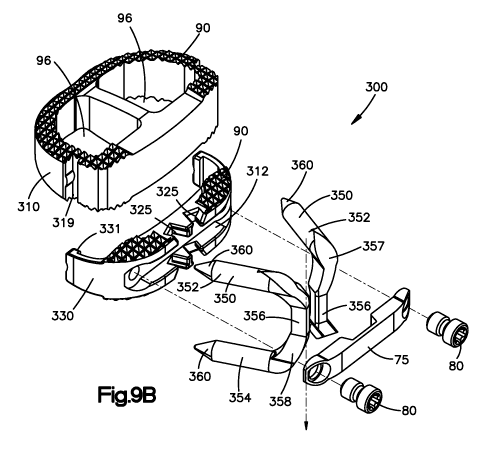
[0031] Fig. 9A illustrates a top perspective view of an intervertebral implant
according to a fourth preferred embodiment of the present application;
6
CA 02734507 2011-02-16
WO 2010/028045 PCT/US2009/055733
[0032] Fig. 9B illustrates an exploded, top perspective view of the
intervertebral
implant shown in Fig. 9A;
[0033] Fig. 1OA illustrates a side perspective view of an intervertebral
implant
according to a fifth preferred embodiment of the present application;
[0034] Fig. I OB illustrates a front perspective view of the intervertebral
implant
shown in Fig. 10A;
[0035] Fig I OC illustrates a side perspective view of the intervertebral
implant
shown in Fig. 10A, the intervertebral implant inserted into an intervertebral
disc space
between adjacent vertebral bodies;
[0036] Fig. I OD illustrates a side perspective view of an alternate exemplary
embodiment of the intervertebral implant shown in Fig. 10A, wherein the plate
portion
and the blade elements are integrally formed;
[0037] Fig. 11 illustrates a rear perspective view of the intervertebral
implant
shown in Fig. 1 OA incorporating alternate exemplary blade elements;
[0038] Fig. 12 illustrates a top perspective view of the intervertebral
implant
shown in Fig. 11 incorporating separate superior and inferior blade receiving
channels;
[0039] Fig. 13 illustrates a top perspective view of the intervertebral
implant
shown in Fig. 11 incorporating an integrated keel extending from the top and
bottom
surfaces thereof, and
[0040] Figs. 14-17 illustrate various views of an exemplary method for
inserting
an intervertebral implant according to the present invention into an
intervertebral disc
space between adjacent vertebral bodies, the intervertebral implant being
coupled to an
exemplary insertion and guide instrument.
7
CA 02734507 2011-02-16
WO 2010/028045 PCT/US2009/055733
DETAILED DESCRIPTION OF THE INVENTION
[0041] Certain terminology is used in the following description for
convenience
only and is not limiting. The words "right", "left", "lower", "upper", "top",
and "bottom"
designate directions in the drawings to which reference is made. The words
"inwardly"
or "distally" and "outwardly" or "proximally" refer to directions toward and
away from,
respectively, the geometric center of the intervertebral implant, spacer,
blade elements
and related parts thereof. The words, "anterior", "posterior", "superior",
"inferior" and
related words and/or phrases designate preferred positions and orientations in
the human
body to which reference is made and are not meant to be limiting. The
terminology
includes the above-listed words, derivatives thereof and words of similar
import.
[0042] Similar reference numerals will be utilized throughout the application
to
describe similar or the same components of each of the preferred embodiments
of the
intervertebral implant described herein and the descriptions will focus on the
specific
features of the individual embodiments that distinguish the particular
embodiment from
the others.
[0043] Preferred embodiments of the present application are directed to an
implant 1, 100, 200, 300, 400, 400' ("1-400"), preferably an intervertebral
implant 1-400.
It should be understood that while the various embodiments of the
intervertebral implant
1-400 will be described in connection with spinal surgery, those skilled in
the art will
appreciate that the intervertebral implant 1-400, as well as the components
thereof, may
be used for implantation into other parts of the body, including, for example,
long bones
or bones in the hand, face, feet, extremities, cranium or nearly any bone in
the human
body including the knee, hip, shoulder, finger or other joint replacement or
for bone
8
CA 02734507 2011-02-16
WO 2010/028045 PCT/US2009/055733
augmentation. For example, the implant 1-400 may be used to fix a fracture of
a long
bone B (Figs. 2A-2D), for retaining a graft therein, or in cases where it is
desirable to
lengthen a long bone B, the implant 1-400 may be inserted into a surgically
created
fracture between bone portions B 1, B2 of the long bone B and then fixed to
the bone
portions B1, B2. For example, the implant 1-400 may be inserted between the
bone
portions B 1, B2 to fix the bone portions B 1, B2 together, such as in the
case of a fracture
between the bone portions B1, B2.
[0044] The various embodiments of the implant 1-400 are preferably sized and
configured to be implanted between adjacent vertebral bodies V. The
intervertebral
implant 1-400 may be sized and configured to replace all or substantially all
of an
intervertebral disc space D between adjacent vertebral bodies V or only part
of the
intervertebral disc space D. In addition, the preferred intervertebral implant
1-400 may
be configured to replace an entire vertebral body V and related disc spaces D
or multiple
disc spaces D in a patient's spine, as would be apparent to one having
ordinary skill in the
art based upon a review of the present application. The intervertebral implant
1-400 may
be adapted for use in the anterior, antero-lateral, direct lateral, extra-
foraminal,
transforaminal, and posterior approaches for insertion into the spine.
[0045] The intervertebral implant 1-400 of each of the preferred embodiments
preferably includes a spacer portion 10, 110, 210, 310, 410, 410' ("10-410"),
preferably
an intervertebral spacer portion 10-410, sized and configured for implantation
into the
intervertebral disc space D between adjacent vertebral bodies V. The spacer
portion 10-
410 of each of the preferred embodiments includes a top surface 11, a bottom
surface 12,
a first side surface 13, a second side surface 14, a leading surface 15 and a
trailing surface
9
CA 02734507 2011-02-16
WO 2010/028045 PCT/US2009/055733
16. The top and bottom surfaces 11, 12 are suitable for contacting and are
adapted for
being secured relative to the end plates of adjacent vertebral bodies V. The
interbody
spacer portion 10-410 is preferably sized and configured to maintain and/or
restore a
desired intervertebral disc height between the adjacent vertebral bodies V.
The trailing
surface 16 preferably includes a recess 112 for receipt of a blocking plate
75, as will be
described in greatly detail below.
[0046] The top and bottom surfaces 11, 12 may include a series of teeth,
ridges,
spikes or other similar projections 90 to aid in securing the intervertebral
implant 1-400
to the endplates of the adjacent vertebral bodies V. Alternatively and/or in
addition, the
implant 1-400 may include one or more bone fixation elements 442, preferably
bone
screws 442 (referring to Figs. 10A-11), and/or the top and bottom surfaces 11,
12 may
include one or more keels 92 (referring to Fig. 13) for securing the
intervertebral implant
1-400 to the adjacent vertebral bodies V.
[0047] The top and bottom surfaces 11, 12 may also include a curved or a
tapered
surface to help provide an anatomical shape for mating with the patient's
spine, to mate
with a surface of one of the fractured bone portions B 1, B 1 or to orient the
endplates of
the adjacent vertebral bodies V in a desired manner. The particular surface
shape and
curvature, taper or alternate surface feature in the anterior-posterior
direction, as well as
the particular surface shape and curvature, taper or alternate surface feature
in the medial-
lateral direction will depend upon the location where the intervertebral
implant 1-400 is
intended to be implanted and/or surgeon preferences or whether the implant 1-
400 is
utilized in a long bone B or other area in the body.
CA 02734507 2011-02-16
WO 2010/028045 PCT/US2009/055733
[0048] The intervertebral implant 1-400 of the preferred embodiments also
includes a longitudinal axis 2 that extends between the top surface 11 and the
bottom
surface 12 and is preferably, generally parallel to the cranial-caudal axis of
the spine.
The intervertebral implant 1-400 also includes an anterior-posterior axis 3
that extends
generally parallel to the anterior-posterior axis of the spine or generally
perpendicular to
the aforementioned longitudinal axis 2. The intervertebral implant 1-400
further includes
a medial-lateral axis 4 that extends generally parallel to the medial-lateral
axis of the
spine or generally perpendicular to the aforementioned longitudinal and
anterior-posterior
axes 2, 3.
[0049] The implant 1-400 may also include one or more openings, windows or
channels for receiving bone graft material. For example, the implant 1-400 may
include
one or more vertical openings, windows or channels 96 extending through the
implant 1-
400 from the top surface 11 to the bottom surface 12 for insertion of bone
graft material,
such that bone growth is promoted through the vertical openings, windows or
channels 96
following implantation of the intervertebral implant 1-400. Alternatively or
in addition,
the implant 1-400 may include one or more horizontal openings, windows or
channels 97
extending through the implant 1-400 from the first side surface 13 to the
second side
surface 14 and/or from the leading surface 15 to the trailing surface 16 for
receiving bone
graft material that may also promote fusion through and around the spacer
portion 10-
410.
[0050] The implant 1-400 preferably also includes one or more blade receiving
channels 25, 125, 225, 325, 425 ("25-425") configured for mating with the one
or more
blade elements 50, 150, 250, 350, 450, 450' ("50-450") so that, in use, after
the implant
11
CA 02734507 2011-02-16
WO 2010/028045 PCT/US2009/055733
1-400 has been inserted into the intervertebral disc space D between adjacent
vertebral
bodies V, the implant 1-400 may be secured to the adjacent vertebral bodies V
by one or
more blade elements 50-450. The blade elements 50-450 preferably limit
relative motion
between the implant 1-400 and the adjacent vertebral bodies V in an implanted
configuration. The intervertebral implant 1-400 is preferably fixedly secured
to the
adjacent vertebral bodies V, so that, even if the boney structure of the
vertebral bodies V
is weakened, there is no loosening between the intervertebral implant 1-400
and the
vertebral bodies V. The intervertebral implant 1-400 preferably provides an
assembly for
interbody fusion and for allowing boney fusion to occur while potentially
eliminating
additional fixation hardware such as pedicle screws and rods or plates.
[0051] The intervertebral implant 1-400 may also include the optional blocking
plate 75 for reducing the likelihood that the blade elements 50-450 may
postoperatively
uncouple from the implant 1-400 and migrate from the disc space D. In use, the
blocking
plate 75 is affixed to the intervertebral implant 1-400 after the blade
elements 50-450
have been coupled to the implant 1-400 and adjacent vertebral bodies V. The
blocking
plate 75 is preferably secured to the implant 1-400 via a fastener 80. The
fastener 80 is
preferably a screw for threadably engaging the blocking plate 75 to the
implant 1-400.
The blocking plate 75 preferably covers at least a portion of the blade
elements 50-250 to
prevent the blade elements 50-250 from backing out. More preferably, the
blocking plate
75 is secured to the implant 1-400 and covers at least a portion of the
trailing portion of
the blade elements 50-250, as will be described in greater detail below. The
preferred
threaded screw fastener connection between the blocking plate 75 and the
implant 1-400
preferably draws the blade elements 50-250 and the implant 1-400 more closely
together
12
CA 02734507 2011-02-16
WO 2010/028045 PCT/US2009/055733
in order to provide a more rigid construct. Alternatively, as will be
appreciated by one of
ordinary skill in the art, the blocking plate 75 may be secured using any
other coupling
mechanism now or hereafter known for such purpose including, but not limited
to, a
snap-lock, a quarter-turn locking mechanism, a press-fit taper lock, etc.
Alternatively,
the coupling mechanism may be incorporated into the blocking plate 75 such
that the
blocking plate 75 secures itself thereto.
[0052] The implant 1-400 including the spacer portion 10-4 10 and the blades
50-
250 may be constructed of any suitable biocompatible material or combination
of
materials including, but not limited to one or more of the following metals
such as
titanium, titanium alloys, stainless steel, aluminum, aluminum alloy,
magnesium, etc.,
polymers such as, PEEK, porous PEEK, carbon fiber PEEK, resorbable polymers,
PLLA,
etc., allograft, synthetic allograft substitute, ceramics in the form of
bioglass, tantalum,
Nitinol, or alternative bone growth material or some composite material or
combination
of these materials. As will be appreciated by one of ordinary skill in the
art, the implant
1-400 may also be coated with various compounds to increase bony on-growth or
in-
growth, promote healing, or allow for revision of the implant, including
hydroxyapatite,
titanium-nickel, vapor plasma spray deposition of titanium, or plasma
treatment to make
the surface hydrophilic.
[0053] Referring to Figs. IA, lB and 3A-4, the intervertebral implant 1 of a
first
preferred embodiment includes the interbody spacer portion 10 and one or more
of the
blade elements 50. The intervertebral implant 1 is preferably adapted for
anterior
insertion, but is not so limited and may be otherwise inserted into a disc
space.
13
CA 02734507 2011-02-16
WO 2010/028045 PCT/US2009/055733
[0054] The interbody spacer portion 10 is constructed as a hollow body, which
includes the vertical opening, window or channel 96 extending from the top
surface 11 to
the bottom surface 12 and has a general kidney-bean shape. Alternatively, as
will be
appreciated by one of ordinary skill in the art, the interbody spacer portion
10 may
assume the structure and geometry of any number of now known or hereafter
developed
spacer implants.
[0055] The interbody spacer portion 10 of the first preferred embodiment
includes
two blade receiving channels 25 for accommodating a pair of the blade elements
50. In
the first preferred embodiment, each of the channels 25 is formed in the
trailing surface
16 and extends across the top and bottom surfaces 11, 12 to the leading
surface 15 of the
implant 1. Alternatively, as will be appreciated by one of ordinary skill in
the art, the
blade receiving channels 25 may only be formed in the trailing surface 16, may
be
eliminated entirely so that the blades 50 may be implanted into the adjacent
vertebral
bodies V and optionally, connected to one another independent of and not
mechanically
coupled to the interbody spacer portion 10.
[0056] The blades 25 may assume a range of geometries to adapt to user
preferences, patient anatomy, various applications, etc. Referring to Figs.
3A, 3B and
5A, the blades 50 preferably include a superior portion 52, an inferior
portion 54, and a
trailing portion 56. The superior and inferior portions 52, 54 generally
extend in the
anterior-posterior direction and extend superiorly and inferiorly of the top
and bottom
surfaces 11, 12, respectively, of the implant 1 for engaging the adjacent
vertebral bodies
V while the trailing portion 56 generally extends in the cranio-caudal
direction for
insertion into the blade receiving channels 25 formed in the trailing surface
16 of the
14
CA 02734507 2011-02-16
WO 2010/028045 PCT/US2009/055733
implant 1. The superior portions 52 of the first and second blade elements 50
extend
superiorly of the top surface 11 of the spacer portion 10 and the inferior
portion 54 of the
first and second blade elements 50 extend inferiorly of the bottom surface 12
of the
spacer portion 10 in an assembled configuration.
[0057] The superior portion 52 is preferably angled obliquely at a first blade
angle 0 (Fig. 1) with respect to the longitudinal axis 2. The inferior portion
54 is also
preferably angled obliquely at a first blade angle 0 with respect to the
longitudinal axis 2.
The trailing portions 56 are preferably, generally parallel to the
longitudinal axis 2.
Alternatively, the superior and inferior portions 52, 54 may extend generally
parallel to
the anterior-posterior axis 3 from the trailing surface 16 toward the leading
surface 15
(generally illustrated in Figs. 1 OA-1 OD), may extend in a generally arcuate
path
(generally illustrated in Fig. 6) or any combination thereof. In addition, the
superior
portion 52 of the blades 50 preferably extends from the trailing portion 56
toward the
leading surface 15 at a second blade angle A relative to the anterior-
posterior axis 3. The
inferior portion 54 of the blades 50 may also be similarly oriented relative
to the spacer
portion 10 and/or the longitudinal and anterior-posterior axes 2, 3. Such
orientation of
the blades 50 relative to the longitudinal and anterior-posterior axes 2, 3
inhibits backout
of the implant 1-400 through the incision through which that implant 1-400 was
inserted.
[0058] Referring to IA, 1B, 3A, 3B and 6, the blades 50 preferably are coupled
to
the implant 1 and the adjacent vertebral bodies V along a pair of divergent
and/or curved
paths with respect to the longitudinal and anterior-posterior axes 2, 3 from
the trailing
surface 16 to the leading surface 15. The inclusion of the blades 50 that
diverge with
respect to the longitudinal and anterior-posterior axes 2, 3 enables the
implant 1 to resist
CA 02734507 2011-02-16
WO 2010/028045 PCT/US2009/055733
translational forces transmitted to the implant 1 when the vertebral bodies V
attempt to
slide anteriorly. In addition, this geometry preferably forces the adjacent
vertebral bodies
V into compression about the implant 1 during insertion of the blades 50. The
inclusion
of the divergent blades 50 with respect to the longitudinal and anterior-
posterior axes 2, 3
along a curved path may be particularly well suited for insertion in through a
minimal
invasive surgical procedure. Alternatively, the blades 50 may diverge along a
linearly
divergent path.
[0059] Preferably, the blade elements 50 are designed to create compression
across the implant 1 by creating a difference in the first blade angle 0 of
the blades 50
with respect to the longitudinal axis 2 between the leading and trailing ends
of the blades
50. That is, for example, the leading end of the superior and inferior
portions 52, 54 of
the blade elements 50 may have a greater first blade angle 0 than the trailing
ends of the
superior and inferior portions 52, 54 of the blade elements 50 with respect to
the
longitudinal axis 2 so that the advancement of the blades 50 into the adjacent
vertebral
bodies V draws the adjacent vertebral bodies V together about the implant 1.
Such a
feature may reduce the relaxation of the ligaments which may result in the
loosening of
the implant 1.
[0060] The oblique angles of the superior and inferior portions 52, 54 of the
blades 50 can be characterized by defining the blade angle 0 between about ten
(10 ) and
about eighty degrees (80 ) with respect to the longitudinal axis 2 and serve
to limit
anatomical motions of the adjacent vertebral bodies V, such as extension and
lateral
bending, that tend to separate the vertebral bodies V from the implant 1 and
impede
fusion.
16
CA 02734507 2011-02-16
WO 2010/028045 PCT/US2009/055733
[0061] Referring to Figs. 3A, 3B and 5A, the blades 50 may further include a
superior intermediate trailing portion 58 for interconnecting the superior
portion 52 to the
trailing portion 56 and an inferior intermediate trailing portion 60 for
interconnecting the
inferior portion 54 to the trailing portion 56. The superior and inferior
intermediate
trailing portions 58, 60 may be obliquely angled with respect to the trailing
portion 56.
The superior and inferior intermediate trailing portions 58, 60 may also be
tilted
obliquely with respect to the trailing portion 56 in an anterior-posterior
direction.
[0062] The blades 50 may also include a superior leading portion 62 and an
inferior leading portion 64, wherein the superior leading portion 62 may be
obliquely
angled with respect to the superior portion 52. Similarly, the inferior
leading portion 64
may be obliquely angled with respect to the inferior portion 54. The superior
and inferior
leading portions 62, 64 may also be tilted obliquely with respect to the
superior and
inferior portions 52, 54.
[0063] As best shown in Fig. 5A, inner edges of the superior leading portion
62,
the superior portion 52, the superior intermediate trailing portion 58, the
trailing portion
56, the inferior intermediate trailing portion 60, the inferior portion 54 and
the inferior
leading portion 64 preferably define a cavity 65. That is, the trailing
portion 56 may
terminate prior to the leading edge of the blades 50, thereby defining the
cavity 65. The
trailing portion 56 may alternatively be eliminated such the blades 50 are
mounted to the
top and bottom surfaces 11, 12 of the implant 1. The blades 50 preferably have
a
generally C-shape defined by the superior portion 52, the inferior portion 54
and the
trailing or intermediate portion 56 with the cavity 65 defined therein and
opening
proximate the leading portion 62.
17
CA 02734507 2011-02-16
WO 2010/028045 PCT/US2009/055733
[0064] The blades 50 may also include a cutting feature or sharp edge 51 on
their
leading and/or outer edges such that the blades 50 may be urged or impacted
into the
adjacent vertebral bodies V or to ease initial insertion of the leading and/or
outer edges
into a pre-cut channel in the vertebral bodies V. The blades 50 may be urged
and/or
impacted into the vertebral bodies V without the use of tool cutting
instrumentation and
while using a relatively minimal surgical incision. Alternatively, a separate
tool cutting
instrument may be used to form the blade receiving channels in the adjacent
vertebral
bodies V, as will be described in greater detail below.
[0065] Referring to Fig. 5A, the blade elements 50 may be solid.
Alternatively,
as shown in Figs. 5B and 5C, the blade elements 50', 50" may include one or
more voids
66 therethrough to allow bone-ingrowth to interdigitate with the blade
elements 50', 50"
imparting additional unity between the implanted blade elements 50', 50" and
the boney
environment of the vertebral body V. Alternatively or in addition, referring
to Fig. 5D,
the blade elements 50"' may include anti-repulsion surface features, such as
serrations or
shark teeth 67, to assist in preventing the blade elements 50"' from backing
out of the
bone and to allow bone growth between the teeth of the serrations 67.
[0066] Alternatively, the blades 50 may assume other geometries now or
hereafter developed. For example, the cavity 65 may be eliminated (not shown)
such that
the blades 50 extend from the inferior portion 54 to the superior portion 52.
In such a
configuration, the blades 50 may be mounted to the top and bottom surfaces 11,
12.
Alternatively, the blades 50 may be configured in a generally X-shape or other
similar
configuration (not shown) so that the blade elements overlap one another such
that a first
blade element extends between a superior right side to an inferior left side
and a second
18
CA 02734507 2011-02-16
WO 2010/028045 PCT/US2009/055733
blade element extends between a superior left side to an inferior right side
such that the
blade elements form an X when viewed from the trailing surface. Alternatively,
the blade
elements may be integrally formed in an X-shape (not shown). Further, the
orientation of
the blades 50, when viewed from the trailing surface along the anterior-
posterior axis 3,
can be rotated by ninety degrees (90 ) such that each blade element interfaces
with only a
single vertebral body V and couples to the implant 10 or to the other blade
element. In
addition, the blade elements 50 may be formed from a single component whose
flexible
construction, for example, a Nitinol construction assists in creating a
diverging pattern by
way of the blade receiving channels 25 within the interbody spacer portion 10.
[0067] The blade elements 50 are preferably integrally formed. Alternatively,
the
blade elements 50 may be formed from multiple different elements, which are
then
coupled together by any means now or hereafter developed including but not
limited to
bonding, a mechanical connection, etc.
[0068] In use, the interbody spacer portion 10 is preferably inserted into the
desired intervertebral disc space D or void created by the removal of at least
a portion of
an intervertebral disc. The blade elements 50 may be impacted so that they are
received
within the blade receiving channels 25 formed in the interbody spacer portion
10. The
blade elements 50 may also simultaneously cut or form a channel into the
adjacent
vertebral bodies V. The blade elements 50 may be impacted so that insertion of
the blade
elements 50 into the blade receiving channels 25 and the adjacent vertebral
bodies V is
performed without the use of a tool cutting instrument and with a relatively
minimal
surgical incision. Alternatively, as will be appreciated by one of ordinary
skill in the art,
a chisel, broach, saw, drill, milling system, or any other tool cutting
instrument may be
19
CA 02734507 2011-02-16
WO 2010/028045 PCT/US2009/055733
used to cut a channel through a portion of the adjacent vertebral bodies V
prior to
implantation of the blade elements 50. For example, referring to Figs. 14-17,
a tool
cutting instrument 530 may be guided to cut a channel through a portion of the
adjacent
vertebral bodies V prior to implantation of the blade elements 50, as will be
described in
greater detail below. Alternatively, the interbody spacer portion 10 and the
blade
elements 50 may be coupled together and subsequently inserted together as an
assembly
into the disc space D, with or without the use of a precut channel in the
adjacent vertebral
bodies V.
[0069] Referring to Figs. 7A-7D, an intervertebral implant 100 in accordance
with a second preferred embodiment is similar to the first preferred
embodiment of the
implant 10. The intervertebral implant 100 of the second preferred embodiment
includes
a spacer portion 110 and one or more blade elements 150. In the second
preferred
embodiment, the blade receiving channels 125 are preferably formed in the
trailing
surface 16 of the spacer portion 110 from the top surface 11 to the bottom
surface 12
only. The blade elements 150 preferably include a superior portion 152, an
inferior
portion 154, and a trailing portion 156. The superior and inferior portions
152, 154
generally extend in the anterior-posterior direction and are located
superiorly and
inferiorly of the top and bottom surfaces 11, 12, respectively, of the spacer
portion 110
for engaging the adjacent vertebral bodies V while the trailing portion 156
generally
extends in the cranio-caudal direction for insertion into the blade receiving
channels 125
formed in the trailing surface 16 of the spacer portion 110.
[0070] In the second preferred embodiment, the inner edges of the blade
elements
150 do not contact the top and bottom surfaces 11, 12 of the spacer portion
110 adjacent
CA 02734507 2011-02-16
WO 2010/028045 PCT/US2009/055733
to the leading surface 15 of the implant 100. The blades 150 are preferably
coupled to
the implant 100 and the adjacent vertebral bodies V along a pair of divergent,
curved
paths, similar to the implant 10 of the first preferred embodiment.
Alternatively, the
superior and inferior portions 152, 154 of one or more of the blade elements
150 may
extend generally parallel from the trailing surface 16 to the leading surface
15 (referring
to Figs. 1OA-IOD) or any combination thereof.
[0071] The blades 150 may also include a cutting feature or sharp edge 151 on
their leading surfaces so that the blades 150 can be impacted or otherwise
urged into the
adjacent vertebral bodies V and into the blade receiving channels 125 formed
in the
implant 100 without the use of tool cutting instrumentation and while using a
relatively
minimal surgical incision. Alternatively, a separate tool cutting instrument
may be used
to form the blade receiving channels in the adjacent vertebral bodies V, as
will be
described in greater detail below.
[0072] The implant 100 may also include a blocking plate 75 and one or more
fasteners 80 for securing the blocking plate 75 to the trailing surface 16 of
the spacer
portion 110. More preferably, the trailing surface 16 of the spacer portion
110 includes a
recess 112 for receiving the blocking plate 75. As previously described, in
use, after the
implant 100 has been inserted into the intervertebral disc space D and the
blades 150
have been inserted into the blade receiving channels 125 formed in the spacer
portion 110
and into the adjacent vertebral bodies V, the blocking plate 75 can be coupled
to the
spacer portion 110 via one or more fasteners 80 to prevent the blades 150 from
backing
out. The blocking plate 75 is preferably received in the recess 112 to limit
the protrusion
of the blocking plate 75 from the trailing surface 16 and from a profile of
the patient's
21
CA 02734507 2011-02-16
WO 2010/028045 PCT/US2009/055733
spine. Limiting protrusion of the blocking plate 75 from the profile of the
patient's spine
generally limits contact between the blocking plate 75 and vessels, nerves or
other
anatomy adjacent the patient's spine.
[0073] Referring to Figs. 8A and 8B, an intervertebral implant 200 in
accordance
with a third preferred embodiment includes a spacer portion 210, a plate
portion 230 and
one or more blade elements 250. The implant 200 is similar to the first and
second
preferred embodiments of the implant 10, 100 described above. The
intervertebral
implant 200 of the third preferred embodiment includes a plate portion 230
coupled to the
spacer portion 210. The plate portion 230 is preferably mounted to the
trailing surface 16
of the spacer portion 210 and preferably does not extend beyond the vertical
or lateral
perimeter of the interbody spacer portion 210. That is the height of the plate
portion 230
is preferably no more than the height of the interbody spacer portion 210 so
that the plate
portion 230 does not increase the height profile of the interbody spacer
portion 210 and
the width of the plate portion 230 does not extend beyond a width of the
spacer portion
210. In this manner, the intervertebral implant 200 has a low profile.
Additionally, in
this manner, the plate portion 230 may be entirely implanted into the
intervertebral disc
space D between the adjacent vertebral bodies V such that the plate portion
230 does not
extend beyond an edge of the disc space D. In use, the plate portion 230 may
be sized
and configured so that the top and bottom surfaces of the plate portion 230
contact the
endplates of the adjacent vertebral bodies V. Alternatively, the plate portion
230 may be
sized and configured so that only the spacer 210 contacts the adjacent
vertebral bodies V.
For example, the height of the plate portion 230 may be small enough so that
it does not
22
CA 02734507 2011-02-16
WO 2010/028045 PCT/US2009/055733
contact the vertebral bodies V when connected to the spacer portion 210 in an
implanted
position.
[0074] The plate portion 230 may be coupled to the interbody spacer portion
210
by any coupling mechanism now or hereafter known. For example, the spacer
portion
210 may include one or more recesses 319 (shown in Fig. 9B) formed in the side
or
trailing surfaces for engaging one or more projections 331 (shown in Fig. 9B)
extending
from the plate portion 230. Other coupling mechanisms for coupling the plate
portion
230 to the spacer portion 210 are disclosed in International Application No.
PCT/US2008/082473 filed on November 5, 2008 and entitled, "Low Profile
Intervertebral Implant", the contents of which are hereby incorporated by
reference in
their entirety.
[0075] The spacer portion 210 may be constructed of any biocompatible material
or combination of materials as previously described. The plate portion 230 may
be
formed of a different material than the spacer 210. For example, the plate
portion 230
may be formed of a metallic material such as, a titanium or a titanium alloy,
or a polymer
such as, PEEK, and the spacer 210 may be formed of a non-metallic material
such as, an
allograft, a bioresorbable material, a ceramic, etc. Alternatively, the plate
portion 230
and the spacer 210 may be formed from the same material. For example, the
plate
portion 230 and the spacer 210 may both be constructed of tantalum nitride
(TaN).
[0076] The plate portion 230 preferably further includes the blade receiving
channels 225 for receiving the blade elements 250. The blade elements 250 may
have
any shape and configuration as disclosed herein. Referring to Fig. 8B, the
blades 250 are
preferably tapered in the cranial-caudal direction so that when the tapered
surfaces are
23
CA 02734507 2011-02-16
WO 2010/028045 PCT/US2009/055733
drawn together during the insertion of the blade elements 250 and, optionally,
the final
tightening of the blocking plate 75, the implant 200 becomes a rigid construct
and thus
provides an environment for fusion. The tapered geometry of the blade elements
250
further allows a significant portion of the endplates of the adjacent
vertebral bodies V to
be spared from embedding of the blade elements 250 thus reducing the
invasiveness of
the surgical procedure. Alternatively, it is envisioned that the blade
elements 250 may be
integrally formed with the plate portion 230, as will be described in greater
detail below.
[0077] The implant 200 of the third preferred embodiment may also include a
blocking plate 75 and one or more fasteners 80 for securing the blocking plate
75 to the
trailing surface of the plate portion 230. More preferably, the trailing
surface of the plate
portion 230 includes a recess 212 for receiving the blocking plate 75. As
previously
described, in use, after the implant 200 has been inserted into the
intervertebral disc space
D and the blades 250 have been inserted into the blade receiving channels 225
formed in
the plate portion 230 and into the adjacent vertebral bodies V, the blocking
plate 75 can
be coupled to the plate portion 230 via one or more fasteners 80 to inhibit
the blades 250
from backing out relative to the plate portion 230.
[0078] It should be noted, that it is envisioned that the plate portion 230
and the
blades 250 may be used without the spacer portion 210 coupled thereto. For
example, it
is envisioned that the user may insert the spacer portion 210 separately and
uncoupled
from the plate portion 230. Alternatively, the user may elect to fill the disc
space with
bone graft material in place of the spacer portion 210 and then insert only
the plate
portion 230 and the blades 250 or an integrally formed combination of the
plate portion
230 and blades 250 (See Fig. I OD).
24
CA 02734507 2011-02-16
WO 2010/028045 PCT/US2009/055733
[0079] Referring to Figs. 9A and 9B, an intervertebral implant 300 in
accordance
with a fourth preferred embodiment includes an interbody spacer portion 310, a
plate
portion 330 and a pair of blade elements 350. The plate portion 330 is
operatively
coupled to the spacer portion 310 as previously described. The plate portion
330
preferably includes a plurality of blade receiving channels 325 for receiving
the pair of
blade elements 350.
[0080] The fourth preferred embodiment of the intervertebral implant 300 is
similar to the intervertebral implants 10, 100, 200 of the first through third
preferred
embodiments. However, in the fourth preferred embodiment the superior and
inferior
portions 352, 354 of the blade elements 350 are in the form of cylindrical
pins 360, in
contrast to the generally flatter blade portions, for example, superior and
inferior portions
52, 54 of the first preferred embodiment. By incorporating and/or substituting
cylindrical
pins 360 for the blade elements 350, stress concentration on the vertebral
endplates
caused by insertion of the cylindrical pins 360 may be generally reduced
compared to the
relatively flat blades of the first, second and third preferred embodiments.
In addition,
insertion of the cylindrical pins 360 enables the user to pre-drill boreholes
into the
adjacent vertebral bodies V for receiving the pins 360. Drilling boreholes
typically limits
chiseling and/or hammering and chiseling and/or hammering may require exertion
of
significant force by a surgeon in very dense bone (sclerotic bone).
[0081] The blade elements 350 may include a trailing portion 356 for
interconnecting the top and bottom cylindrical pins 360 or for connecting the
blade
elements 350 to the spacer portion 310 or to the plate portion 330. Preferably
the
cylindrical pins 360 and trailing portion 356 are integrally formed.
Alternatively, the
CA 02734507 2011-02-16
WO 2010/028045 PCT/US2009/055733
cylindrical pins 360 and trailing portion 356 may be separately formed and
coupled
together by any means now or hereafter developed including but not limited to
bonding,
mechanical connection, etc. Alternatively, it is envisioned that the blade
elements 360
may be integrally formed with the plate portion 330, as will be described in
greater detail
below.
[0082] The cylindrical pins 360 generally extend in the anterior-posterior
direction and are located superiorly and inferiorly of the top and bottom
surfaces,
respectively, of the spacer portion 310 for engaging the adjacent vertebral
bodies V while
the trailing portion 356 generally extends in the cranio-caudal direction for
insertion into
the blade receiving channels 325 formed in the trailing surface of the plate
portion 330.
The blade elements 350 may further include a superior intermediate trailing
portion 357
for interconnecting the superior pin 360 to the trailing portion 356 and an
inferior
intermediate trailing portion 358 for interconnecting the inferior cylindrical
pin 360 to the
trailing portion 356 so that the superior and inferior cylindrical pins 360
may be angled
and/or titled with respect to the trailing portion 356, as previously
mentioned.
[0083] In use, the spacer portion 310 and the plate portion 330 may be
inserted
into the desired intervertebral disc space D or void created by the removal of
at least a
portion of an intervertebral disc. The blade elements 350 are then preferably
guided into
predrilled boreholes formed in the adjacent vertebral bodies V and impacted,
if necessary,
into the blade receiving channels 325 formed in the plate portion 330.
[0084] The implant 300 may also include a blocking plate 75 and one or more
fasteners 80 for securing the blocking plate 75 to the trailing surface of the
plate portion
330. More preferably, the trailing surface of the plate portion 330 include a
recess 312
26
CA 02734507 2011-02-16
WO 2010/028045 PCT/US2009/055733
for receiving the blocking plate 75. As previously described, in use, after
the implant 300
has been inserted into the intervertebral disc space D and the blades 350 have
been
inserted into the blade receiving channels 325 formed in the plate portion 330
and into
the adjacent vertebral bodies V, the blocking plate 75 can be coupled to the
plate portion
330 via one or more fasteners 80 to prevent the blades 350 from backing out.
In the
fourth preferred embodiment, the blades 350 are preferably inserted along a
longitudinal
axis of the pins 360 and the trailing portions 356 are received into the blade
receiving
channels 325 that are angled relative to the anterior-posterior axis 3 to
accommodate such
insertion of the blades 350.
[0085] Referring to Figs. l0A-IOC, an intervertebral implant 400 in accordance
with a fifth embodiment preferably includes an interbody spacer portion 410.
In the fifth
preferred embodiment, the intervertebral implant 400 is preferably adapted as
a stand
alone, laterally insertable implant 400. That is, the implant 400 is sized and
configured to
be inserted using a direct lateral trans-psoas approach that reduces the need
for
supplemental rigid fixation such as lateral plates and posterior pedicle
screws.
[0086] The interbody spacer portion 410 preferably includes a top surface 411,
a
bottom surface 412, a first side surface 413, a second side surface 414, a
leading surface
415 and a trailing surface 416. The leading surface 415 of the implant 400
preferably has
a bullet-nosed or tapered geometry to facilitate distraction between the
adjacent vertebral
bodies V during implant insertion or to generally facilitate initial insertion
of the spacer
portion 410 into the disc space D. In the fifth preferred embodiment, the
first and second
side surfaces 413, 414 of implant 400 each have a length that is longer than a
distance
between the first and second side surfaces 413, 414 or a length of the leading
and trailing
27
CA 02734507 2011-02-16
WO 2010/028045 PCT/US2009/055733
surfaces 415, 416 so that, upon implantation, the implant 400 has a medial-
lateral width
that is generally longer than its anterior-posterior depth. The interbody
spacer portion
410 is preferably manufactured from a radiolucent polymer, although the spacer
portion
410 may be made from other biocompatible materials as outlined above. The top
and
bottom surfaces 411, 412 of the spacer portion 410 may include a plurality of
teeth,
ridges, spikes or other topographical features 90 to facilitate fixation of
the spacer portion
410 to the adjacent vertebral bodies V.
[0087] As previously described above in connection with the third and fourth
embodiments, the intervertebral implant 400 of the fifth preferred embodiment
includes a
plate portion 430 operatively coupled to the trailing surface 416 of the
spacer portion
410. The plate portion 430 preferably includes one or more blade receiving
channels 425
for receiving one or more blade elements 450 for engaging the adjacent
vertebral bodies
V. The superior and inferior portions of the blade element 450 are preferably
in the form
of cylindrical pins 460. More preferably, as shown, the blade element 450
includes a top
cylindrical pin 460 for engaging a first vertebral body V, a bottom
cylindrical pin 460 for
engaging a second vertebral body V and a trailing portion 456 for
interconnecting the top
and bottom cylindrical pins 460.
[0088] The plate portion 430 preferably also includes a threaded hole 461 for
threadably engaging an insertion and guide instrument 500, as will be
described in greater
detail below. The threaded hole 461 preferably is sized and configured to
couple a
blocking plate 75 via a fastener 80, as previously described, so that when all
of the blade
elements 450 are inserted into the blade receiving channels 425 formed in the
plate
28
CA 02734507 2011-02-16
WO 2010/028045 PCT/US2009/055733
portion 430, the blades 450 are preferably fixed to the implant 400 via the
blocking plate
75 and fastener 80.
[0089] In use, the blade elements 450 are designed to engage the cortical and
cancellous bone of the adjacent vertebral bodies V when the implant 400 is
positioned
within the intervertebral disc space D. The blade elements 450 stabilize the
motion
segment in bending, shear and rotation before fusion occurs. In this fifth
preferred
embodiment, each blade elements 450 is preferably inserted at a different
angle with
respect to a medial plane. Since the blade elements 450 are all inserted at
different angles
there is no one direction in which the implant 400 will not resist migration.
Once the
implant 400 and blade elements 450 have been rigidly attached via the blocking
plate 75
and fastener 80 to the plate portion 430, the implant 400 will resist movement
of the
motion segment in bending, shear and rotation. This design will allow the
surgeon to
stabilize a motion segment to create an environment conducive to interbody
fusion,
generally without the use of anterior column plating or posterior screw/rod
fixation. This
allows the surgeon to create a stable interbody fusion construct from a direct
lateral
approach while containing all of the stabilization hardware within the
confines of the
anterior column.
[0090] As shown, the implant 400 of the fifth preferred embodiment and,
specifically, the plate portion 430, may also include one or more bone
fixation holes 440
for receiving one or more bone fixation elements or screws 442 for securing
the
intervertebral implant 400 to the adjacent vertebral bodies V. The bone
fixation elements
442 are not limited to bone screws and may be comprised of a helical nail, a
distally
expanding nail or screw, etc. More preferably, the plate portion 430 includes
at least two
29
CA 02734507 2011-02-16
WO 2010/028045 PCT/US2009/055733
bone fixation holes 440 for receiving two bone fixation elements 442 with at
least one
bone fixation element 442 being angled down for engaging the lower vertebral
body V
and at least one bone fixation element 442 being angled up for engaging the
upper
vertebral body V. It should be understood however that the number of bone
fixation
elements 442 extending from the top and bottom surfaces 411, 412 may be varied
and
that the number of bone fixation elements 442 extending from the top surface
411 need
not equal the number of bone fixation elements 442 extending from the bottom
surface
412. Exit openings for the bone fixation holes 440 may be formed in the plate
portion
430 and/or in the spacer portion 410. The bone fixation holes 440 may also
include one
or more threads (not shown) for threadably engaging threads formed on a head
portion of
the bone fixation elements 442 in order to secure the bone fixation elements
442 to the
plate portion 430.
[0091] It should be noted, that while the blade elements 450 are preferably in
the
form of cylindrical pins 460 (as shown in Figs. l0A-IOC), referring to Fig.
11, the blade
elements 450 may be in the form of flatter blades as previously described and
illustrated
above. Moreover, referring to Fig. 12, the plate portion 430 may include two
or more
blade receiving channels 425, wherein each blade 450 includes a trailing
portion 456 for
receipt within one of the rod receiving channels 425 and a blade portion 452,
454 for
engaging one of the adjacent vertebral bodies V. Referring to Fig. 13, the
implant 400 of
the fifth preferred embodiment may also include one or more keels 92 extending
from top
and bottom surfaces 411, 412 of the spacer portion 410 instead of the bone
fixation
elements 442 for engaging the adjacent vertebral bodies V.
CA 02734507 2011-02-16
WO 2010/028045 PCT/US2009/055733
[0092] Referring to Fig. I OD, the intervertebral implant 400' of the fifth
preferred
embodiment may include a plate portion 430' for operatively engaging the
spacer portion
410' and one or more blade elements 450' for engaging the adjacent vertebral
bodies V,
wherein the blades 450' are integrally formed with the plate portion 430'. In
this manner,
the implant 400' may be sequentially inserted such that the spacer 410' may be
initially
inserted into the intervertebral disc space and the plate portion 430' with
integral blades
450' may be sequentially inserted thereafter. Alternatively, the plate portion
430' with
integral blades 450' may be initially coupled to the spacer 410' so that the
spacer 410',
the plate portion 430' and the blades 450' may be inserted simultaneously. The
plate
portion 430' may be coupled to the spacer 410' by any mechanism now or
hereafter
known for such purpose including, but not limited to, interlocking projections
and
recesses, a threaded connection, adhesive, bonding, etc.
[0093] Referring to Figs. 14-17, an exemplary insertion and guide instrument
500
is preferably configured to facilitate insertion of the implant 1-400
including the spacer
portion 10-4 10, plate portion 230, 330, 430 and blade elements 50-450, and
the formation
of blade receiving channels in the adjacent vertebral bodies V for receiving
the blade
elements 50-450.
[0094] The insertion and guide instrument 500 preferably includes a shaft 510
having a distal end 512 for operatively engaging an intervertebral implant 1-
400 to
facilitate insertion of the implant 1-400 into the intervertebral disc space
D. The shaft
510 may be coupled to the implant 1-400 by any coupling mechanism now or
hereafter
known for such purpose. For example, the shaft 510 may include a threaded stem
(not
shown) extending from the distal end 512 for engaging a threaded bore formed
in the
31
CA 02734507 2011-02-16
WO 2010/028045 PCT/US2009/055733
trailing surface of the implant 1-400. The shaft 512 preferably also includes
a stop 515 to
prevent over insertion of the implant 1-400 into the disc space D and thus to
facilitate
optimal positioning of the implant 1-400 with respect to the adjacent
vertebral bodies V.
The shaft 510 preferably also includes a guide 520 for aligning a cutting tool
530 (Figs.
14 and 15).
[0095] The cutting tool 530 preferably includes a shaft 532 and a cutting tip
534
for forming blade receiving channels in the adjacent vertebral bodies V for
receiving the
blades 50-450. In use, the cutting tool 530 may be powered such as, for
example, via a
reciprocating power tool, or hand powered such as, for example, by a mallet or
by force
applied directly by hand. The cutting tool 530 preferably also includes a
pivot 535 such
as, for example, a pivot pin or universal ball joint. The pivot 535 allows the
cutting tip
534 to be movably disposed with respect to both the shaft 532 of the cutting
tool 530 as
well as the superior and inferior vertebral bodies V throughout a range of
angles.
[0096] In use, the insertion and guide instrument 500 is coupled to the
implant 1-
400. The implant 1-400 is then inserted into a disc space D following, for
example, a
partial or full discectomy. The insertion and guide instrument 500 is advanced
into the
disc space D until the stop 515 abuts the adjacent vertebral bodies V. Once
the implant
1-400 is positioned within the intervertebral disc space D, the cutting tool
530 is inserted
into and through the guide 520 and advanced into the adjacent vertebral bodies
V,
thereby forming blade receiving channels in the adjacent vertebral bodies V
for receiving
the blade elements 50-450. Thereafter, the cutting tool 530 is removed and the
blade
elements 50-450 are advanced through the guide 520 and into the preformed
blade
receiving channels. The cutting tool 530 is preferably configured to create
blade
32
CA 02734507 2011-02-16
WO 2010/028045 PCT/US2009/055733
receiving channels that are in a size, shape and/or configuration of the blade
element 50-
450 that is being utilized with one or the preferred implants 1-400.
[0097] Alternatively, the cutting tool 530 may be eliminated and the blade
elements 50-450 may be inserted without preformed blade receiving channels
formed in
the vertebral bodies V. For example, the blade elements 50-450 may be inserted
into the
adjacent vertebral bodies V by gentle mallet blows to the ends of a blade
insertion and
guide instrument 500 or any other method of urging the blades 50-450 into the
adjacent
vertebral bodies V.
[0098] Referring to Figs. 9A-1 OC, in the fourth and fifth preferred
embodiments,
where the blade elements 450 incorporate cylindrical pins 460, the guide 520
is
preferably sized and configured to guide a drill bit (not shown) in order to
form
corresponding boreholes in the adjacent vertebra bodies V for receiving the
cylindrical
pins 360. Thus, in one exemplary method of inserting the intervertebral
implants 300,
400 of the fourth and fifth preferred embodiments into the disc space D
between first and
second vertebral bodies V, the user may insert the implants 300, 400
including, for
example, the interbody spacer portion 310, 410 and the plate portion 330, 430
via an
insertion and guide instrument 500. Thereafter, using the guide 520
operatively coupled
to the insertion and guide instrument 500, the user may drill one or more
boreholes in the
first vertebral body V and one or more boreholes into the second vertebral
body V. Next,
the user may guide first and second blade elements 350, 450 into the first and
second
blade receiving channels 325, 425 formed in the plate portion 330, 430 and
into the
predrilled first and second boreholes formed in the first and second vertebral
bodies V.
The predrilled boreholes preferably have a smaller diameter than a diameter of
the
33
CA 02734507 2011-02-16
WO 2010/028045 PCT/US2009/055733
cylindrical pins 360, 460, resulting in a force-fit between the cylindrical
pins 360, 460
and the predrilled boreholes. The user may then couple a blocking plate 75 to
the trailing
surface of the implant 300, 400 to prevent backing out of the blade elements
350, 450.
[0099] It is envisioned that the one or more blade elements 50-450 could be
adapted for use in anchoring a disc arthroplasty device (not shown) instead of
a fusion
spacer 1-400 using similar blade receiving channels 25-425 or by separating
the superior
and inferior portions of each of the blade element 50-450 and coupling them
directly to
the endplates of the disc arthroplasty device or dynamic full disc replacement
device.
[00100] As will be appreciated by those skilled in the art, any or all of the
components described herein may be provided in sets or kits so that the
surgeon may
select various combinations of components to form an implant and create a disc
replacement system which is configured specifically for the particular
needs/anatomy of a
patient. It should be noted that one or more of each component may be provided
in a kit
or set, including the instruments and tools. In some kits or sets, the same
component or
part may be provided in different shapes and/or sizes. The surgeon or staff
may mix and
match the first and second parts to create the implant before or during the
procedure.
[00101] While the foregoing description and drawings represent the preferred
embodiments of the present invention, it will be understood that various
additions,
modifications, combinations and/or substitutions may be made therein without
departing
from the spirit and scope of the present invention as defined in the
accompanying claims.
In particular, it will be clear to those skilled in the art that the present
invention may be
embodied in other specific forms, structures, arrangements, proportions, and
with other
elements, materials, and components, without departing from the spirit or
essential
34
CA 02734507 2011-02-16
WO 2010/028045 PCT/US2009/055733
characteristics thereof. One skilled in the art will appreciate that the
invention may be
used with many modifications of structure, arrangement, proportions,
materials, and
components and otherwise, used in the practice of the invention, which are
particularly
adapted to specific environments and operative requirements without departing
from the
principles of the present invention. In addition, features described herein
may be used
singularly or in combination with other features. The presently disclosed
embodiments
are therefore to be considered in all respects as illustrative and not
restrictive, the scope
of the invention being indicated by the appended claims, and not limited to
the foregoing
description.