Note: Descriptions are shown in the official language in which they were submitted.
CA 02734657 2011-03-22
Portind2-CONCRETE 4038013:3
CONCRETE MATERIAL DISPENSING SYSTEM
Related Applications
[0001] This application claims priority as a continuation-in-part to U.S.
Patent
Application No. 12/470,671 titled Concrete Material Dispensing System and
filed on
May 22, 2009, which claims priority under 35 U.S.C. 119(e) to U.S.
Provisional
Application No. 61/055,647 titled Concrete Material Dispensing System and
filed on
May 23, 2008, both of which are fully incorporated by reference herein.
Technical Field
[0002] Control and monitoring systems for concrete plants including admixture
formulation and dispensing.
Background
[0003] Concrete plants dispense concrete ingredients, mixed concrete, or both,
either individually or combined, depending on their design. Different types of
concrete
plants satisfy different needs and are used according to a variety of
conditions, including
the availability of raw materials for concrete, where the concrete is to be
used, how
much concrete is needed, and environmental concerns, to name a few.
[0004] One type of concrete plant dispenses mainly admixtures used in concrete
recipes. Admixtures are materials, other than cement, aggregate, fibers,
fines, and
water, used to make concrete. Admixtures may be added to a concrete batch
before or
during the mixing period and are used to alter the properties of the fluid
concrete, the
set concrete, or both. Common admixtures include retardants, accelerators,
plasticizers, water reducers, air-entrainers, colorants, and shrinkage
reducers. To
ensure a high quality finished concrete, an admixture and its constituents
should be
accurately measured according to the concrete batch recipe, that is, relative
to the
measured amounts of the other ingredients constituting a batch of concrete.
1
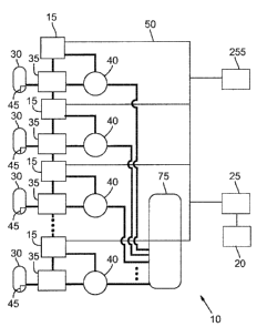
CA 02734657 2011-03-22
Portlnd2-CONCRETE 40380/3:3
[0005] Other types of concrete plants dispense dry materials such as
aggregate,
fines, and cement and the water and admixtures are added to the concrete at-
the job
site. Yet other concrete plants dispense dry materials as well as water,
admixtures, or
both, for example, the materials may be deposited into a vehicle equipped with
a mixer,
or into a mixing chamber at the plant. Concrete plants of the various types
may be
stationary, designed to be moved relatively easily, or may be portable.
[0006] Concrete plants are typically integrated systems employing numerous
components. Silos or bins are commonly used to store aggregate, fines, and
cement.
Tanks store water. Other tanks store premixed admixtures or admixture raw
components (collectively "admixtures") used for various concrete recipes.
Conveyors,
cranes, chutes, pipes and pumps, or other equipment is commonly used to fill
the silos,
bins, and tanks, as well as move concrete ingredients from their storage
places to
dispensing or mixing equipment. Measuring equipment is used to weigh or
otherwise
measure the amount of ingredients used for a concrete batch when the
ingredients are
moved from their storage places to dispensing or mixing equipment. Various
hoses,
pipes, valves, sensors, and sources of pressurized fluids are commonly used to
move
ingredients, operate pumps, and perform other tasks for a concrete plant.
Current Concrete Plant Operations
[0007] Concrete plant operators commonly design or receive building
specifications
for a batch of concrete. Building specifications may be standardized depending
on the
use for the concrete, or may be customized for particular concrete projects.
Building
specifications typically provide requirements for the properties of a batch of
concrete,
such as the minimum compressive strength when cured, the slump when wet, the
amount of water permeability for the cured concrete, color, etc. Creating
batches of
concrete that meet the building specifications commonly requires a batch
recipe calling
for a mixture of ingredients including cement, aggregates; water, and
admixtures. Using
admixtures in a concrete batch recipe provides a wider range of properties,
for both the
wet concrete and the cured concrete, than using cement, aggregates, and water
alone.
[0008] Meeting building specifications commonly requires a precise amount of
admixtures to be added to a given ratio and amount of cements, such as
Portland
2
CA 02734657 2011-03-22
Portlnd2-CONCRETE 40380/3:3
cement type I-IV, fly ash, and other cement materials, aggregates, and water.
Therefore, companies that manufacture admixtures have developed application
specific
admixture recipes, where various admixture recipes are used with basic
concrete
recipes (that is, recipes for the amount of cements, aggregates, and water) to
alter the
properties of the basic concrete recipes to meet standardized building
specifications,
such as a department of transportation's building specification for concrete
used for
highway construction. Of course, meeting specialized building specifications
requires
developing a customized admixture recipe.
[0009] Using admixtures commonly requires complex calculations. Customized
admixture recipes require accounting for the unique building specifications as
well as
the materials used to create the concrete. But, even application specific
admixture
recipes commonly need to be modified because of variables such as the
temperature
and moisture content of the materials used to make a batch of concrete,
environmental
factors such as temperature and humidity, and the type of materials available
(such as
the type or source of cements, or the type or source of aggregates) for making
a batch
of concrete. However, admixtures are commonly pre-mixed before delivery to a
concrete plant and therefore admixtures are not typically modified.
[0010] To create a concrete batch meeting the requirements for a building
specification, concrete plant operators commonly call or send an electronic
message
with the building specifications to an admixture company. Currently, admixture
companies typically call or send an electronic message to the concrete plant
providing
the types and amounts of admixtures needed to meet the building
specifications.
Depending on the type of batch panel a concrete plant has, the concrete plant
operator
either inputs the admixture recipe into a batch panel computer, or operates
the batch
panel to dispense the types and amounts of admixtures in the recipe.
[0011] Existing batch panels include a range of electronic sophistication from
logic
circuits that generate continuous-time electrical signals to operate concrete
plant
equipment, to computerized systems employing antiquated, out-of-date computer
systems, to modern computer systems. Existing batch panels therefore create a
range
of signals from continuous-time electrical signals, for example, signals
having various
3
CA 02734657 2011-03-22
Portlnd2-CONCRETE 40380/3:3
frequencies, waveforms, or both, to digital signals including digital signal
formats used
by various computer systems.
[0012] Concrete plant operators use the batch panel to control concrete plant
equipment to implement concrete recipes. For example, a batch panel with logic
circuits is commonly used to implement a basic concrete recipe as well as an
admixture
recipe by the operator toggling various switches for amounts of time that
depend on the
concrete recipe being implemented. A batch panel with logic circuits typically
provides
little to no feedback regarding the operational status of the concrete plant
equipment
aside from a light or other sign that a switch is in an "on" position.
Computerized batch
panels commonly receive both a basic concrete recipe and an admixture recipe
from
the operator and the computer operates concrete plant equipment to dispense
the
materials, including admixtures (which are typically pre-mixed admixtures),
needed to
create the concrete recipe. Because of the computerization, such batch panels
may
receive limited feedback regarding the operational status of the concrete
plant
equipment, for example, the number of pulses from a flow meter. However,
because
there is typically one batch panel and numerous pieces of equipment,
computerized
batch panels currently require large amounts of wiring between the batch panel
and the
equipment. And, depending on the computer's capabilities, the amount of
information
the batch panel can handle may be limited. Intensive wiring, limited computing
capability, or both, may limit the amount of control, monitoring, and feedback
a batch
panel can provide.
Summary
[0013] The inventors have determined that regardless of the type of concrete
plant or
batch panel, many components in a concrete plant may be controlled, monitored,
or
both, by distributed intelligent controllers. Distributed intelligent
controllers preferably
control operation of concrete plant equipment to implement concrete recipes
and may
record or learn the operational characteristics of the concrete plant. Knowing
the history
of how a component has operated, or how several components have operated and
interacted with one another, may assist a concrete plant operator, admixture
company,
or other suitable entity in knowing what equipment is working when and how,
how much
4
CA 02734657 2011-03-22
Portlnd2-CONCRETE 40380/3:3
inventory is on hand, that is, how much of each material such as admixtures,
concrete,
and aggregate, is available, the usage rate of each material, the life
expectancy for
equipment before replacement or repair is needed, and how to troubleshoot
equipment
to discover the source of a concrete plant problem.
[0014] Various embodiments described below focus on different aspects or
components of concrete plants. Some embodiments relate to control systems, and
in a
particular embodiment to a control system with distributed control aspects
that includes
field boxes to send, receive, generate codes, or all three, related to
concrete plant
operations. In one embodiment, field boxes are preferably printed circuit
boards
contained in a housing and having various components including, but not
limited to, a
programmable device such as a processor, solid state switches, and
communication
ports. The signals, codes, or both preferably relate to operating various
concrete plant
components, reporting the status of various components, determining whether
errors
are occurring or have occurred for various components, tracking and predicting
maintenance needs for various components, tracking and predicting material
replenishment needs, providing alarms, and other concrete plant operations.
[0015] Some embodiments relate to synchronizing the control system elements to
ensure that message traffic does not collide, resulting in missed messages.
Synchronizing the control system elements preferably permits elements to be
added
and removed from the control system without affecting operation of other
elements in
the control system. Further embodiments relate to communication between the
field
boxes and a master controller, and specifically to switching between wireless
communication and wired communication when the ability to communicate
wirelessly, or
over the wired link, is lost.
[0016] Yet other embodiments are directed to detecting an admixture flow loss
between a pump and a mixing chamber. Such flow loss may be due to a leak in
the
hose between the pump and the mixing chamber. Such an embodiment preferably
recognizes when an admixture is deficient because not all of the admixture
materials
were delivered to a mixing tank. Such an embodiment may also help minimize
environmental concerns created by leaking admixtures into the environment.
CA 02734657 2011-03-22
Portind2-CONCRETE 40380/3:3
[0017] In another embodiment, dispensing components are tested and monitored
by
field boxes to determine whether the components are operating within expected
operational ranges when mixed concrete, concrete ingredients, or both, are
dispensed.
The past operational characteristics of the dispensing components is
preferably
determined and used by the field boxes to learn the expected future
operational
characteristics for the dispensing components without preprogramming the field
boxes.
Alternately, the field boxes are pre-programmed with expected future
operational
characteristics for dispensing components. The expected future operational
characteristics are preferably used as an expected measuring specification to
determine
the amount of admixture, other concrete ingredients, or both, dispensed into a
tank,.
mixer, or vehicle.
[0018] Another embodiment relates to equipment inventory and uses unique
identification codes stored in radio frequency identification devices (RFID)
attached to
concrete plant components and other equipment. A controller or data gathering
device
transmits information and information stored in the RFID code either
wirelessly or over a
wired connection to a processor with a memory for tracking inventory such as
concrete
plant components, for example, but not limited to, pumps, meters, and valves,
for
equipment inventory tracking and management.
[0019] Another embodiment relates to an animator for trouble shooting,
concrete
plant operations monitoring, concrete plant operations analysis, or other
functions. The
animator preferably uses information, such as operational codes, stored by a
data
recorder, a modified data recorder, an off-site computer, or both, and
preferably
receives operation, alarm, and error codes transmitted by field boxes. A data
recorder
or computer preferably stores the codes in a file that is interpreted by the
animator to
play back the processes that occurred during the concrete plant operation. The
interpreted codes are preferably graphically displayed as an animation to
permit
concrete plant operators to analyze and understand what processes, alarms, and
errors
occurred. Other embodiments relate to an animator operating on a handheld
device for
playing back the processes and errors and providing recommendations based on
the
processes, alarms, and errors that occurred.
6
CA 02734657 2011-03-22
Portlnd2-CONCRETE 40380/3:3
[0020] Other embodiments relate to transmitting building specifications to a
batch
computer and translating recipes from the batch computer to digital files
readable by a
master controller and implemented, at least in part, by distributed
intelligent controllers.
The master controller preferably decodes the recipe files from the batch
computer and
sends the translated recipes to the distributed intelligent controllers to
operate concrete
plant equipment to create a concrete batch based on the recipe from the batch
computer. Other embodiments relate to the master controller translating
messages,
operations, alarms, and errors reported by the distributed intelligent
controllers and
sending the translated messages to the batch computer.
[0021] Additional aspects and advantages will be apparent from the following
detailed description of preferred embodiments, which proceeds with reference
to the
accompanying drawings.
Brief Description of the Drawings
[0022] FIG. 1 is a schematic illustration of a control system for concrete
plants.
[0023] FIG. 1A is another schematic illustration of a control system for
concrete
plants.
[0024] FIG. 2 is another schematic illustration of a control system for
concrete plants.
[0025] FIG. 3 is another schematic illustration of a control system for
concrete plants.
[0026] FIG. 4 is a schematic illustration of a control system for multiple
concrete
plants.
[0027] FIG. 5 is a schematic illustration of another control system for
multiple
concrete plants.
[0028] FIG. 6 is a flow chart for a method of synchronizing control system
components.
[0029] FIG. 7 is a screen shot of an animation based on concrete plant
operation
codes.
[0030] FIG. 8 is a schematic illustration of a control system for dispensing
concrete
ingredients.
[0031] FIG. 9 is a flow chart for a method of a field box learning operational
parameters of a concrete plant.
7
CA 02734657 2011-03-22
Portlnd2-CONCRETE 40380/3:3
[0032] FIG. 10 is a flow chart for a method of a batch computer scheduling
material
delivery.
[0033] FIG. 11 is an exemplary embodiment of a printed circuit board for a
field box.
[0034] FIG. 12 is the opposite side of the exemplary embodiment of the printed
circuit board of FIG. 11.
[0035] FIG. 13 is a schematic illustration of another control system for
dispensing
concrete ingredients.
[0036] FIG. 14 is a flow chart for a method for creating customized
admixtures.
[0037] FIG. 15 is top-side view of an exemplary embodiment of a printed
circuit
board for another field box.
[0038] FIG. 16 is a bottom-side view of an exemplary embodiment of an edge
connector for the field box of FIG. 15.
[0039] FIG. 17 is a review view of an exemplary embodiment of communication
devices for the field box of FIG. 15.
[0040] FIG. 18 is another schematic illustration of a control system for
concrete
plants.
Detailed Description of Preferred Embodiments
[0041] Throughout the disclosure, references to a concrete plant include
facilities
where concrete is manufactured, made, assembled, mixed, or dispensed, as well
as
facilities that manufacture, make, assemble, mix, or dispense ingredients for
use in
concrete, including, but not limited to admixtures, aggregate, fines, cement,
and water.
References to a concrete plant also include facilities that are similar in
function,
construction, or operation to a concrete plant, but are not concrete plants,
for example,
asphalt or other paving plants, granaries, or other suitable facilities. While
exemplary
embodiments are described with respect to dispensing admixtures at a central-
mix
concrete plant, such as concrete plant 90 (FIG. 3), it is intended that
similar control
systems could be used with other types of concrete plants, with multiple
concrete
plants, and with concrete recipes including ingredients other than admixtures
as well as
with concrete recipes having no admixtures.
8
CA 02734657 2011-03-22
Portind2-CONCRETE 40380/3:3
Intelligent Controller Concrete Plant Retro-Fit
[0042] FIG. 1 schematically illustrates an embodiment of a system for retro-
fitting, or
upgrading, an existing concrete plant 10 to include distributed intelligent
controllers,
such as field boxes 15, to control and monitor concrete plant equipment,
regardless of
the existing batch panel 20. FIG. 1A schematically illustrates another
embodiment of a
system for retro-fitting, or upgrading, an existing concrete plant 10A to
include
distributed intelligent controllers, such as field boxes 15A, to control and
monitor
concrete plant equipment, regardless of the existing batch panel 20A.
[0043] With reference to FIG. 1, providing distributed intelligent
controllers, such as
field boxes 15, preferably enables a concrete plant 10 to increase concrete
batch
repeatability, operate with improved safety, or monitor and record plant
operations. The
following discussion is made with reference to a master controller 25 that
instructs field
boxes 15 to control equipment to implement an admixture recipe, however the
master
controller 25 may be configured to instruct distributed controllers, such as
field boxes
15, to control equipment and implement a concrete recipe without admixtures,
or to
implement a concrete recipe including admixtures and cements, aggregates, and
water.
[0044] Concrete plant 10 includes four tanks 30 to hold admixtures. More or
fewer
tanks may be included. Each tank 30 has an associated pump 35 and flow meter
40,
and preferably a level sensor 45 that generates signals or codes relating to
the amount
of fluid in each tank 30. Signals and codes are described in greater detail
below. A
field box 15, or other suitable intelligent controller, is also associated
with each tank 30.
Each field box 15 preferably communicates with, controls, or both, concrete
plant 10
equipment associated with the same tank 30, such as a pump 35, flow meter 40,
and
level sensor 45. Each field box 15 is preferably located proximate the
equipment it
communicates with, controls, or both, thus reducing or eliminating the need
for relatively
long runs of wire between each piece of equipment and its controller.
[0045] The field boxes 15 communicate with one another over an electronic
interface
50, preferably a controller-area network bus interface ("CAN-bus").
Communications
between field boxes 15 is further described below. The master controller 25
communicates with the electronic interface 50, and thus with each field box
15. The
master controller 25 also communicates with the batch panel 20. For example,
the
9
CA 02734657 2011-03-22
Portlnd2-CONCRETE 40380/3:3
master controller 25 is preferably directly connected to the batch panel 20 by
plain
wiring, USB, Ethernet, SCSI, Zigbee , BlueTooth , RS485 or RS232 protocol, or
other
suitable communication connection. The' master controller 25 preferably serves
as a
translator, permitting instructions from the batch panel 20 to be communicated
to the
field boxes 15 over the electronic interface 50. For example, if the batch
panel 20
contains logic circuits and transmits signals as continuous-time electrical
signals, that is,
analog signals, the master controller 25 receives such continuous-time
electrical signals
and converts them to a format for transmission over the electronic interface
50. Thus,
distributed intelligent controllers, such as field boxes 15, are added to
existing concrete
plants 10 without replacing the batch panel 20, and without extensive wiring
connected
between the concrete plant equipment and a centralized controller. In
preferred
embodiments, the master controller 25 translates the signals received from the
batch
panel 20 to CAN-bus signals for transmission over the electronic interface 50,
which is
preferably a CAN-bus. The field boxes 15 preferably include a programmable
device,
such as a processor, capable of receiving and acting on the CAN-bus signals.
Field
boxes are described in greater detail below.
[0046] As described in further detail below, the field boxes 15 preferably
control
operation of the concrete plant equipment, such as pumps 35, flow meters 40,
and level
sensors 45, as well as report on the operational status of each piece of
equipment.
Adding distributed, intelligent controllers, such as field boxes 15, to a
concrete plant 10
preferably permits intelligent operation of the current concrete plant 10 at a
local level,
that is, intelligent decisions regarding equipment operations preferably
occurs at a
location proximate individual pieces of equipment. Such localized control
preferably
permits rapid decisions. to be made by the intelligent controllers based on
equipment
operating parameters without delays commonly associated with relatively long
communication paths where messages and instructions may become lost or
delayed,
queued decision making by a centrally located computer, or human error, such
as
misinterpreting or not seeing an error message. Preferably, intelligent
controllers,
sensors, and a master controller are all that is required to add to an
existing concrete
plant 10 to enable distributed intelligent control of the plant 10.
CA 02734657 2011-03-22
Portlnd2-CONCRETE 40380/3:3
[0047] The master controller 25 may include a programmable logic device and a
memory to record operational parameters of the equipment, or may be connected
to a
computer or other suitable device for tracking the operational parameters of
the
concrete plant equipment. Recording operational parameters is described in
greater
detail below.
[0048] With reference to FIG. 1A, providing distributed intelligent
controllers, such as
field boxes 15A, preferably enables a concrete plant 10 to increase concrete
batch
repeatability, operate with improved safety, or monitor and record plant
operations
without a master controller, such as master controller 25 (FIG. 1). The
following
discussion is made with reference to field boxes 15A that control equipment to
implement an admixture recipe, however the field boxes 15A may be configured
to
control equipment and implement a concrete recipe without admixtures, or to
implement
a concrete recipe including admixtures and cements, aggregates, and water.
[0049] Concrete plant 10A includes four tanks 30A to hold admixtures. More or
fewer tanks may be included. Each tank 30A has an associated pump 35A and flow
meter 40A, and preferably a level sensor 45A that generates signals or codes
relating to
the amount of fluid in each tank 30A. A field box 15A, or other suitable
intelligent
controller, is also associated with each tank 30A. Each field box 15A
preferably
communicates with, controls, or both, one or more of concrete plant 1 OA
equipment
associated with the same tank 30A, such as a pump 35A, flow meter 40A, and
level
sensor 45A. Each field box 15A is preferably located proximate the equipment
it
communicates with, controls, or both, thus reducing or eliminating the need
for relatively
long runs of wire between each piece of equipment and its controller.
[0050] The field boxes 15A may communicate with one another over an electronic
interface 50A, for example, as described above, but in a preferred embodiment
field
boxes 15A communicate with the batch panel 20A over an electronic interface
50A that
includes one or more strands of ordinary copper wire. Each field box 15A
includes
hardware, firmware, software, or other suitable programming to perform some or
all of
the functions performed by a master controller, such as master controller 25
(FIG. 1).
Each field box 15A preferably directly receives instructions from the batch
panel 20 via
the electronic interface 50A, for example, in the form of electrical pulses
sent over a
11
CA 02734657 2011-03-22
Portlnd2-CONCRETE 40380/3:3
wire, and implements such instructions. Preferably, each field box 15A
receives
different instructions via the electronic interface 50A, but one or more field
boxes 15A
may receive the same instructions.
[0051] For example, if the batch panel 20A contains logic circuits and
transmits
signals as continuous-time electrical signals, that is, analog signals, each
field box 15A
receives such continuous-time electrical signals, for example via wire strands
connected
between the batch panel 20A and a particular field box 15A, and converts such
signals
to a format for implementation. Thus, distributed intelligent controllers,
such as field
boxes 15A, are added to existing concrete plants 10A without replacing the
batch panel
20A, and without replacing existing wiring connected between the concrete
plant
equipment and a centralized controller, such as batch panel 20A. An exemplary
field
boxes 15A preferably includes hardware, such as an optical isolator for
sensing the
presence or absence of a voltage or sensing contact closures from sources
emitting 90
to 140 VAC or DC voltages. Additional input circuitry preferably senses an
"on" or "off'
condition by sensing AC or DC voltage levels between 90-140 volts. The input
circuitry
is preferably designed with filtering on the input and a hysteresis amplifier
for high noise
rejection and relatively transient-free clean switching. An exemplary field
box 15A
preferably provides up to 4000 volts (transient) of optical isolation between
the concrete
plant equipment and a centralized controller, such as batch panel 20A, that
are
connected to the logic output to the microcontroller circuit or processor of
the field box
15A. A field box 15A also preferably includes a programmable device, such as a
microcontroller circuit or a processor, capable of receiving and acting on the
signals
transmitted by batch panel 20A regardless of whether such signals are analog
or digital
signals.
[0052] Like field boxes 15, the field boxes 15A preferably control operation
of the
concrete plant equipment, such as pumps 35A, flow meters 40A, and level
sensors 45A,
as well as report on the operational status of each piece of equipment. Adding
distributed, intelligent controllers, such as field boxes 15A, to a concrete
plant 10A
preferably permits intelligent operation of the current concrete plant 1 OA at
a local level,
that is, intelligent decisions regarding equipment operations preferably
occurs at a
location proximate individual pieces of equipment. Such localized control
preferably
12
CA 02734657 2011-03-22
Portlnd2-CONCRETE 40380/3:3
permits rapid decisions to be made by the intelligent controllers based on
equipment
operating parameters without delays commonly associated with relatively long
communication paths where messages and instructions may become lost or
delayed,
queued decision making by a centrally located computer, or human error, such
as
misinterpreting or not seeing an error message. Additionally, intelligent
controllers,
such as field boxes 15A, may include batch panel functionality. For example, a
field box
15A may be programmed such that local activation of a button on a field box
15A
causes a preset amount of an admixture to flow into mixing bottle 75A.
Preferably,
intelligent controllers such as field boxes 15A are all that is required to
add to an
existing concrete plant 1 OA to enable distributed intelligent control of the
plant 1 OA.
[0053] Field boxes 15A may include a programmable logic device and a memory to
record operational parameters of the equipment, or may be connected to a
computer or
other suitable device for tracking the operational parameters of the concrete
plant
equipment.
Automating Recipes
[0054] FIG. 2 illustrates a schematic diagram for another embodiment where a
system automates recipe implementation. Again, the embodiment is described
with
reference to automating an admixture recipe, but alternate embodiments may
automate
basic concrete recipes both with and without admixture recipes. Elements
common
between FIGS. 1 and 2 are given the same reference numeral.
[0055] In addition to the master controller 25 communicating with the batch
panel 20
and the electronic interface 50, the master controller 25 communicates with a
batch
computer, or batch computer system, 55. Preferably, the master controller 25
communicates with the batch computer 55 over a second electronic interface 60,
such
as a USB, Ethernet, or other suitable interface.
[0056] Depending on the batch panel 20, the master controller 25 preferably
receives building specifications from the batch panel 20, translates the
building
specifications into a format suitable for the second electronic interface 60,
and transmits
the translated building specifications to the batch computer 55. If the batch
panel 20
cannot communicate building specifications to the master controller 25, a
concrete plant
13
CA 02734657 2011-03-22
Portlnd2-CONCRETE 40380/3:3
operator preferably calls or sends an electronic message to an admixture
company who
inputs the building specifications into the batch computer 55.
[0057] Once the batch computer 55 receives the building specifications,
software 65
running on the batch computer 55 preferably looks up an appropriate concrete
batch
recipe. An appropriate concrete batch recipe preferably includes a basic
concrete
recipe component and an admixture component. The concrete batch recipes may
reside on the batch computer 55, or on a computer connected to a computer
network
70, such as the Internet. Pre-existing concrete batch recipes may be used, or
customized concrete batch recipes may be used, as described below.
[0058] The batch computer 55 transmits the concrete recipe to the master
controller
25. In preferred embodiments, the master controller 25 translates the
admixture recipe
component of the concrete batch recipe into an appropriate format for the
electronic
interface 50, and transmits the translated admixture recipe to the field boxes
15. The
master controller 25 also preferably translates the basic concrete recipe
component to a
format useable by the batch panel 20 and transmits the translated basic
concrete recipe
to the batch panel 20. The field boxes 15 preferably control concrete plant
equipment to
implement the admixture recipe while the batch panel 20 preferably controls
other
concrete plant equipment to implement the basic concrete recipe. Alternately,
the
master controller 25 may be connected to a printer, video display, or other
suitable
output device to permit an operator to read the basic concrete recipe and use
the batch
panel 20 to implement the basic concrete recipe, for example, when the batch
panel 20
does not include a computer or other programmable device.
[0059] Each field box 15 also preferably monitors the equipment it is
associated with
and generates signals, codes, or messages relating to the operation of each
associated
piece of equipment. The signals, codes, or messages are transmitted over the
electronic interface 50 to the master controller 25 where they are translated
to a format
appropriate for the second electronic interface 60 and transmitted to the
batch computer
55. The batch computer 55 preferably stores the signals, codes, or messages
relating
to equipment operation and associates them with a time stamp, which may also
be
provided by each field box 15. The stored signals, codes, or messages and
associated
14,
CA 02734657 2011-03-22
Portlnd2-CONCRETE 40380/3:3
time stamps are preferably used to recreate operation of the concrete plate
during a
specified time period for troubleshooting or reporting purposes.
[0060] Concrete batch recipes can be stored as an Extensible Markup Language
(XML) file, or may be translated into the XML format by the service 65 running
on the
batch computer 55 if not stored as an XML file. Alternately, the batch recipes
may be
stored on another computer connected to the batch computer 55 via a computer
network 70. Thus, the batch recipes may be in a database operating on a
computer
that can be located anywhere on the computer network 70, such as the Internet.
Formats other than XML are suitable for transmission between the batch
computer 55
and the master controller 25 and may be used.
[0061] Once in the XML language, the recipe is transmitted to the master
controller
25. The software that does this translation is preferably the service 65
running on the
batch computer 55. The service program 65 preferably sends the appropriate
commands to the master controller 25 to instruct the field boxes 15 to create
the
admixture for the appropriate concrete batch recipe. In a preferred
embodiment,
software on the master controller 25 receives the batch recipe in the XML
language and
interprets the batch recipe and converts the batch recipe into CAN-bus
commands. The
CAN-bus commands are sent, either wirelessly, or over a wired connection, as
described below, to one or more field boxes 15. The field boxes 15 preferably
activate
actuators associated with the pumps 35 and flow meters 40 to deliver the
admixture
from the storage tanks 30 to a mixer, such as mixing bottle 75. In alternate
embodiments, a field box 15 may activate actuators to deliver the amount of
water a
batch recipe calls for.
[0062] Alternately, in response to receiving the CAN-bus commands, one or more
of
the field boxes 15 may operate various actuators to measure and dispense the
ingredients needed, for example, to create the entire batch recipe. For
example, in
addition to admixtures as described above, conveyor belts with weighing
equipment
may be used to move and measure the amount of aggregate, fines, and cement
from
their storage areas to a mixer. The mixer may be located in the concrete plant
10, or
may be part of a vehicle (not illustrated). The field boxes 15 are preferably
connected to
electronic actuators and other controllers that operate equipment such as
gates and
CA 02734657 2011-03-22
Portlnd2-CONCRETE 4038013:3
chutes to deliver the concrete ingredients to conveyors, and thus to the
mixer. Other
equipment, such as, but not limited to, pipes used to convey air fluidized
cement, may
be used in alternate embodiments.
[0063] When messages are generated by the field boxes 15 during a batch
recipe's
implementation, or otherwise, the messages may be sent as CAN-bus codes to the
master controller 25. Before the master controller 25 transmits the messages
to the
batch computer 55, the master, controller 25 preferably translates the
messages from
CAN-bus format to XML so the batch computer 55 will be able to interpret and
display
the messages or recipe results of the concrete batch. The messages or the
recipe
results may be used to generate a quality report in the batch computer 55, for
example,
a report noting whether there were any errors and the amount of admixture
dispensed
compared to the amount the batch recipe called for.
[0064] In other embodiments, field boxes 15A may be used to perform the above-
described functions instead of field boxes 15. When field boxes 15A are used,
a master
controller 25 may not be needed.
Exemplary Distributed Control System
[0065] Referring to FIG. 3, an exemplary control system 200 for a concrete
plant 205
is illustrated. The concrete plant 205 includes a plurality of components such
as
storage tanks 210 through 210e, pumps 215 through 215e, meters 220 through
220e,
fill valves 225 through 225e, measure tanks 230 through 230e, discharge valves
235
through 235e. The previously described components are useful for storing and
dispensing fluid ingredients, such as premixed admixtures and admixture raw
components (collectively "admixtures"), or water, used for making a batch of
concrete.
The concrete plant 205 may also contain other components (not illustrated) for
storing,
moving, measuring, and mixing other concrete ingredients such as aggregates,
fines,
and cement.
[0066] A batch of concrete may be made in another part of the concrete plant
205
(not illustrated), or may be made at a different concrete plant or at a
jobsite. The batch
of concrete may be dry, that is, have no water added, or may be hydrated.
Admixtures
16
CA 02734657 2011-03-22
Portfnd2-CONCRETE 40380/3:3
or water from the concrete plant 205 are preferably added to the concrete
batch either
during mixing or after mixing, depending on the batch recipe.
[0067] Various admixtures are stored in the storage tanks 210 through 210e.
The
pumps 215 through 215e pump the admixtures out of the storage tanks 210
through
210e into the measure tanks 230 through 230e when the fill valves 225 through
225e
are open. The meters 220 through 220e measure how much of each admixture is
pumped into the measure tanks 230 through 230e. A single batch of concrete may
not
require admixture from all of the storage tanks 210 through 210e, but may use
the
admixtures from any storage tank 210 through 210e singularly or in any
combination
including all of the storage tanks 210 through 210e. The concrete plant 205 is
not
limited to six storage tanks 210, but may have any number of storage tanks
210. When
any of the storage tanks 210 through 210e contain admixture raw components,
the raw
components are preferably dispensed and blended to create customized
admixtures as
described below.
[0068] When the meters 220 through 220e indicate that an appropriate amount of
admixture has been pumped into the measure tanks 230 through 230e, for
example, an
amount of admixture called for by a concrete batch recipe, the fill valves 225
through
225e are closed and the pumps 215 through 215e are shut off. The measure tanks
230
through 230e preferably have a transparent window to permit visual
confirmation of the
amount of admixture in the measure tanks 230 through 230e. The amount of
admixture
in the measure tanks 230 through 230e is preferably confirmed using two
methods. For
example, the two methods currently used by many existing concrete plants
involves
obtaining readings from meters, such as meters 220 through 220e, and a visual
inspection of the amount of fluid in a measure tank, such as a measure tank
230.
Embodiments described below relate to improved methods for confirming the
amount of
admixture dispensed, either into measure tanks 230 through 230e or into
another
suitable receptacle. The discharge valves 235 through 235e are then opened and
the
admixture in the measure tanks 230 through 230e is discharged, for example,
into a
vehicle for transport to a jobsite. The vehicle may contain other ingredients
such as
cement, aggregate, fines, or water, or such ingredients may be added after the
admixtures are deposited in the vehicle.
17
CA 02734657 2011-03-22
Portlnd2-CONCRETE 40380/3:3
[0069] Each of the components in the concrete plant 205 preferably has a
sensor or
sensors associated with it. Associated sensors include sensors internal to a
component, such as built in sensors, as well as external sensors either
connected to or
proximate a component. For example, the storage tank 210 preferably has a
sensor
inside the storage tank 210 for indicating the fill level, or amount of fluid
in the storage
tank 210. The pump 215 preferably has a sensor or sensors that send signals,
codes,
or both, related to pump 215 operating parameters such as when the pump 215 is
on or
off, whether there is a fill stroke when the fill valve 225 is opened, whether
there are
short pump strokes, whether there are missing pump strokes, whether the pump
outlet
pressure is above or below a minimum pressure per stroke, whether there is a
very
quick pump stroke, whether there is a very slow pump stroke, whether the
average flow
through the pump 215 is too high or too low, the total number of pump strokes,
how may
cycles the pump 215 goes through in a given time period, the amount of time
for each
cycle, and other operating parameters. Each of the operating parameters for
the pump
210 preferably has a unique signal or code associated with it, and an
intelligent
distributed controller, such as a field box 240, processes the signals, codes,
or both, to
derive the parameters for the pump 215. For example, pump 215 may be a
positive
displacement pump or a metering pump that generates a signal when a pump
stroke is
completed, and a field box 240 may receive such signal. Because a positive
displacement pump or a metering pump moves a known amount of fluid with each
stroke, the field box 240 may derive a code from the signal where the code
indicates an
amount of fluid moved by the pump. Signals, codes, or both, are preferably
transmitted
to the field box 240 over a signal path such as one or more wires or cables,
or a
wireless connection, discussed in greater detail below. In alternate
embodiments, the
field box 240 controls the pump 215 and generate codes based on the operation
of the
pump 215. Field boxes 240 are described in more detail below.
[0070] Likewise, the meter 220 preferably has an associated sensor or sensors
for
sending signals, codes, or both, related to meter operating parameters such as
whether
a meter pulse is missing, whether a meter pulse exceeds the count rate, the
meter
pulse rate maximum, the meter pulse rate minimum, the meter pulse rate
average, the
number of meter pulses for a period of time, the total number of meter pulses,
whether
18
CA 02734657 2011-03-22
Portlnd2-CONCRETE 40380/3:3
an amount of water or admixture greater than the measure tank 230 volume has
passed
through the meter 220, whether a measure tank 230 pressure probe provides a
reading
different from the meter 220, and other operating parameters. Each of the
operating
parameters for the meter 220 preferably has a unique signal or code associated
with it,
and a field box 240 preferably processes the signals, codes, or both, to
derive the
above parameters or other suitable parameters. In alternate embodiments, the
field box
240 controls the meter 220 and generate codes based on operation of the meter
220.
[0071] The fill valve 225 preferably has an associated sensor or sensors for
sending
signals, codes, or both related to fill valve 225 operating parameters such as
when the
fill valve 225 is opened or closed, the amount of time the fill valve 225 is
open, the
maximum time the fill valve 225 has been open, the minimum time the fill valve
225 has
been open, the average time the fill valve 225 has been open, the maximum
pressure
through the fill valve 225, the minimum pressure through the fill valve 225,
the average
pressure through the fill valve 225, the total number of fill cycles for the
fill valve 225,
whether the fill valve 225 is stuck in an open position, and other operating
parameters.
Each of the operating parameters for the fill valve 225 preferably has a
unique signal or
code associated with it, and a field box 240 preferably processes the signals,
codes, or
both to derive the above parameters. In alternate embodiments, the field box
240
controls the fill valve 225 and generates codes based on operation of the fill
valve 225.
[0072] The measure tank 230 preferably has an associated sensor or sensors for
sending signals, codes, or both, related to measure tank 230 operating
parameters such
as whether a zero low fill sensor is shorted or held low for more than a given
time, such
as 15 minutes, whether a zero high fill sensor is shorted or held low for more
than a
given time, such as 15 minutes, whether a measure tank 230 overfill probe is
shorted,
whether the measure tank 230 has been overfilled, whether a zero low fill
sensor
detected liquid when the fill valve 225 was opened, whether a zero high fill
sensor
detected liquid when the fill valve 225 was opened, whether a measure tank 230
overfill
probe detected liquid when a test or calibration cycle was run, whether a zero
low fill
sensor detected liquid when a test or calibration cycle was run, whether a
zero high fill
sensor detected liquid when a test or calibration cycle was run, and other
operating
parameters. Each of the operating parameters for the measure tank 230
preferably has
19
CA 02734657 2011-03-22
Portlnd2-CONCRETE 40380/3:3
a unique signal or code associated with it, and a field box 240 preferably
processes the
signals, codes, or both, to derive the above parameters or other suitable
parameters. In
alternate embodiments, the field box 240 controls the measure tank 230 and
generates
codes based on the operation of the measure tank 230.
[0073] The discharge valve 235 preferably has an associated sensor or sensors
for
sending signals, codes, or both, related to discharge valve operational
parameters such
as when the discharge valve 235 is opened or closed, the amount of time the
discharge
valve 235 is open, the maximum time the discharge valve 235 has been open, the
minimum time the discharge valve 235 has been open, the average time the
discharge
valve 235 has been open, the maximum pressure through the discharge valve 235,
the
minimum pressure through the discharge valve 235, the average pressure through
the
discharge valve 235, the total number of discharge cycles for the discharge
valve 235,
whether the discharge valve 235 is stuck in an open position, and other
operating
parameters. Each of the operating parameters for the discharge valve 235
preferably
has a unique signal or code associated with it, and a field box 240 preferably
processes
the signals, codes, or both, to derive the above parameters or other suitable
parameters. In alternate embodiments, the field box 240 controls the discharge
valve
235 and generates codes based on the operation of the discharge valve 235.
[0074] In certain embodiments, the sensors associated with the pump 215, meter
220, fill valve 225, measure tank 230, and discharge valve 235 communicate
with a field
box 240 either over a wireless connection, for example, a radio-frequency
system such
as a Zigbee , Bluetooth , or other suitable communication system, via a wired
connection, for example an electronic interface such as a CAN-bus, an 12C bus,
SMbus,
Universal Serial Bus, or other suitable electronic interface, or both. The
field box 240
preferably contains, in addition to communication equipment, a programmable
device,
such as a microprocessor, a programmable logic device, or other suitable
programmable device, and preferably includes a memory. The memory, if
included,
preferably has a non-volatile and a volatile component for storing field box
programming
and message codes, respectively.
[0075] In alternate embodiments, the components in the concrete plant 205 may
not
have associated sensors and may be directly controlled by a field box 240. For
CA 02734657 2011-03-22
Portlnd2-CONCRETE 40380/3:3
example, the field box 240 may control the operation of the pump 215, the fill
valve 225,
the discharge valve 235, or other components, through electronically
controlled
actuators that are operably connected to the various components. By directly
controlling each component of the concrete plant 205, the field box 240 may
know the
operating condition and parameters of each component. When the field box 240
directly controls the components of the concrete plant 205, signals, codes, or
both,
relating to each component's operating parameters are preferably generated by
the field
box 240. Alternately, the field box 240 may control each component, and each
component may include one or more associated sensors. The associated sensors,
as
well as the field box 240, may generate signals, codes, or both relating to
operational
parameters for the components. In one embodiment, sensors may be used to
confirm
whether an instruction from a field box 240 was successfully completed.
[0076] Each field box 240 through 240e preferably communicates with a master
controller 245 over a wireless connection, via a wired connection, or both. In
some
embodiments, described in further detail below, field boxes 240 through 240e
are
connected to the master controller 245 over both wireless and wired
communication
channels. While six field boxes 240 are depicted and discussed, more or fewer
field
boxes 240 may be employed.
[0077] The master controller 245 receives or records, or both, messages,
codes, or
signals, or all three, originated by the field boxes 240. Signals, codes, or
both,
preferably originate from the various sensors, and are sent to the field box
240 where
additional processing may occur, for example, to derive codes from the signals
if
sensors transmit signals, group the codes into messages, or both.
Alternatively,
signals, codes, or both, may be generated by the various field boxes 240 and
may be
processed, or grouped into messages, or transmitted as the raw codes. Then,
the
codes, messages, or both, are preferably transmitted from the field box 240 to
the
master controller 245 and on to a batch computer 250 in real time, or near to
real time.
The master controller 245 preferably performs any translations needed for the
signals,
codes, messages, or all three, transmitted by the field boxes 240 to be
understood by
the batch computer 250. An operator using the batch computer 250 is thus
preferably
informed of the current operating status of the components of the concrete
plant 205
21
CA 02734657 2011-03-22
Portlnd2-CONCRETE 40380/3:3
based on the signals, codes, or both, originating from the sensors for each
component
of the concrete plant 205, or generated by the field boxes 240, while the
concrete plant
205 is operating. Code grouping and message transmission are described in
further
detail below.
[0078] The field boxes 240 through 240e are preferably wired together. In an
exemplary embodiment where concrete plant 205 is a large plant with multiple
storage
tanks 210 through 210e, the field boxes 240 through 240e are wired together so
that a
message originating at an intelligent controller, such as field box 240e, is
transmitted
through each of the field boxes 240d, 240c, 240b, 240a, and 240 before being
transmitted to the master controller 245. Such a wiring arrangement permits
the field
boxes 240 through 240e to communicate with one another without first
transmitting a
message through the master controller 245. The wireless communication between
the
field boxes 240 through 240e and the master controller 245 is preferably
designed to
enable each field box 240 through 240e to communicate with each of the other
field
boxes 240 through 240e as well as with the master controller 245.
[0079] In other embodiments, field boxes 15A may be used to perform the above-
described functions instead of field boxes 240. When field boxes 15A are used,
a
master controller 245 may not be needed.
Communicating System Events, Warnings, and Error Messages.
[0080] Referring again to FIG. 3, the wireless and wired communication systems
permit the field boxes 240 through 240e to communicate with the master
controller 245.
The master controller 245, in turn, communicates with the batch computer 250,
which
may be located at the concrete plant 205, or may be located at a remote site.
[0081] Signals or codes sent from the various sensors to the field boxes 240
through
240e, or generated by the field boxes 240 through 240e, result in a collection
of codes
at each field box 240. When codes are sent to the field boxes 240 through
240e, the
field boxes 240 simply collect the codes. When signals are sent to the field
boxes 240
through 240e, the field boxes 240 through 240e contain software, hardware, or
a
combination of software and hardware, to interpret the signals to determine
from where
each signal originated and what event each signal is related to. A
corresponding code
22
CA 02734657 2011-03-22
Portlnd2-CONCRETE 40380/3:3
may then be derived by the field boxes 240 through 240e based on the received
signal.
When the field boxes 240 through 240e directly control the components of the
concrete
plant 205 and there are no sensors connected to or associated with the
components of
the concrete plant 205, the field boxes 240 through 240e preferably generate
codes
related to the operation of the components of the concrete plant 205 based on
the field
boxes 240 through 240e controlling the components of the concrete plant 205.
[0082] Each field box 240 through 240e is preferably equipped with a display
242
that displays the codes at the site where each field box 240 through 240e is
located.
The display 242 is preferably a part of each field box 240, but may be located
proximate
each field box 240 and communicate with each field box 240 over a wired or
wireless
connection. The display 242 preferably cycles through the most recently
received,
derived, or generated codes, or may simply display the latest code. Including
a display
242 for each field box 240 through 240e permits on-site operators to recognize
whether
the concrete plant 205 is operating normally. For example, viewing a display
242
provides the operating status of equipment associated with a particular field
box 240, or
whether there is a warning or error based on the code(s) displayed.
[0083] As previously described, a field box 240 preferably generates, derives,
or
collects several codes, singularly or in any combination, and transmits them
to the
master controller 245 based on the codes. As discussed in more detail below,
in certain
embodiments a field box 240 transmits codes or messages, or both, to a data
recorder
to be recorded and forwarded to a message center 260. Preferably, a modified
data
recorder 255 that includes a programmable device and firmware queries field
boxes
240, or sensors associated with concrete equipment, such as tank fluid level
sensors, to
obtain signals or codes. The modified data recorder 255 preferably has the
capability to
derive codes from signals, and to transmit the codes to a message center 260,
for
example. In other embodiments, for example, illustrated in FIG. 2, data
recorder 255
transmits codes or messages, or both, to the batch computer 250 or to the
message
center 260, or both, which also records the codes or messages.
[0084] The message center 260, batch computer 55, or alternately, modified
data
recorder 255, or a computer communicating with computer network 70, preferably
records the codes and creates operational records for the equipment associated
with
23
CA 02734657 2011-03-22
Portlnd2-CONCRETE 40380/3:3
the codes. For example, equipment associated with a particular field box 240
may
generate a series of codes. A code originated by a sensor associated with the
pump
215 may indicate to the field box 240 that the pump 215 was turned on, and at
what
time. A subsequent code may indicate that the fill valve 225 opened, and
another code
may indicate how many meter pulses followed the fill valve 225 being opened.
The next
code may indicate that the high zero sensor 265 for the measure tank 230
detected
admixture, and a subsequent code may indicate that the pump outlet pressure is
below
a minimum pressure per stroke. Upon receiving these codes, the field box 240
may
create a message indicating that the pump 215 is having difficulty and needs
to be
checked immediately and send this message to the master controller 245. The
master
controller 245 may translate the message, if necessary, and transmit the
message to
the batch computer 250. Alternately, referring to FIG. 2, the batch computer
55 may
transmit the message to a computer connected to the computer network 70, for
example, a computer at the message center 260. The batch computer 250, 55 or a
computer connected to the computer network 70 may store the message,
preferably in
a database. The field box 240 may also transmit the message to the data
recorder 255,
which transmits the message to the message center 260 over a communication
system
270, such as a microwave, satellite, wired or a wireless telephone system, the
internet,
fiber optic or other suitable cable, or other suitable communication system.
The
message center 260 preferably transmits the message to a mobile device 275
over a
second communication system 280. Alternately, referring to FIG. 2, a computer
connected to the computer network 70 may transmit the message to a mobile
device,
such as mobile device 275, through the computer network 70.
[0085] Upon receiving the message, the batch computer 250 itself, or an
operator
viewing the message on the batch computer 250 or a mobile device 275,
preferably
transmits a message back to the field box 240 via the master controller 245
instructing
the field box 240 to shut the pump 215 off. If the master controller 245 is
not available,
or no return message is received by the field box 240 in a certain amount of
time, for
example, the field box 240 may take action. For example, based on the codes
described above, the field box 240 may shut off the pump 215 and generate and
send a
24
CA 02734657 2011-03-22
Portind2-CONCRETE 40380/3:3
second message that the pump 215 has been shut off. Alternately, the field box
240
may shut off the pump 215 prior to transmitting any messages.
[0086] In other situations, the field box 240 may not wait to gather, derive,
or
generate a collection of codes before transmitting a message. For example, the
field
box 240 may receive, derive, or generate a code indicating that the fill
pressure of the
measure tank 230 is at its maximum. At the same time, the field box 240 may
shut off
the pump 215 and close the fill valve 225. The field box 240 may then transmit
a
warning message to the master controller 245, which may translate and route
the
message to the batch computer 250, the message center 260, or a computer
connected
to a computer network, such as network 70 (FIG. 2), any of which may transmit
the
message to a mobile device 275. The master controller 245 may also send a
signal or
command back to the field box 240.
[0087] By including an intelligent controller, such as the field boxes 240
through
240e, in close proximity to the equipment of a concrete plant 205, certain
embodiments
may enhance the operating safety of the concrete plant 205. The field boxes
240
through 240e preferably permit on-site operators to be aware of warning and
error
conditions before the conditions become critical, as well as inform off-site
operators of
the operating condition of the concrete plant 205. Many other system events,
warnings,
and errors may be recognized by the field boxes 240 through 240e. Depending on
the
nature of the system event, warning, or error, the field boxes 240 through
240e may
create and transmit messages and cause appropriate actions to occur at the
concrete
plant 205 through electronic actuators or other suitable devices.
[0088] In other embodiments, field boxes 15A may be used to perform the above-
described functions instead of field boxes 240. When field boxes 15A are used,
a
master controller 245 may not be needed.
Additional Communications.
[0089] Referring again to FIG. 3, other embodiments may include additional
communication capabilities. The storage tanks 210 through 210e preferably
include an
internal fill level sensor. The fill level sensor for each of the storage
tanks 210 through
210e sends a signal to a data recorder 255, the field boxes 240 through 240e,
or both.
CA 02734657 2011-03-22
Portind2-CONCRETE 40380/3:3
The field boxes 240 through 240e preferably also send the codes they receive,
derive,
or generate to the data recorder 255. In embodiments where there are multiple
concrete plants 205, the data recorder 255 preferably associates codes and
messages
with a particular concrete plant 205. Referring to FIG. 4, for example, the
fill level signal
from the storage tanks 210 through 210e located in concrete plant 205b and the
codes
received from the field boxes 240 through 240e located in concrete plant 205b
are
preferably grouped together and associated with the concrete plant 205b. The
recorded
codes or messages are preferably used for troubleshooting to determine the
root of
warnings and errors for each of the concrete plants 205a and 205b as discussed
in
further detail below.
[0090] The data recorder 255 preferably communicates with the communication
system 270. Alternately, communication may occur over an electronic interface
50,
thorough a master controller 25, and through a computer network 70 to a
message
center 260 (FIG. 2). Groups of codes, individual codes, or messages associated
with a
particular concrete plant 205 are preferably transmitted by the data recorder
255
through the communication system 270. The communication system 270 transmits
the
codes or messages to the message center 260, which may be operated by an
entity
responsible for servicing the components of the concrete plant 205, or the
field boxes
240 through 240e and the master controller 230 in the concrete plant 205, or
both.
[0091] Either a computer system or personnel at the message center 260
preferably
select one or more of multiple service technicians, for example, to notify
regarding the
codes or messages received from the data recorder 255. In the example
discussed
above where the pump 210 needed to be shut off, the message center 260
preferably
transmits a message over a communication system 280 (which may be different
from,
or the same as, the communication system 270) to a mobile device 275 carried
by or
accessible to the selected service technician(s). The mobile device 275 then
provides
the selected service technician(s) an alert that the pump 215 has been shut
off and
needs to be serviced. Alternately, the message center 260 may communicate with
the
mobile device 275 through computer network 70 (FIG. 2).
[0092] The codes transmitted by the data recorder 255 are not limited to
warnings
and errors that require immediate attention. For example, with reference to
FIG. 4,
26
CA 02734657 2011-03-22
Portlnd2-CONCRETE 40380/3:3
other codes, such as the total number of cycles a pump 215c in the concrete
plant 205a
has been operated, are transmitted as described above to a mobile device 275.
A
service technician, the batch computer 250, or the message center 260
preferably has a
record of how many cycles the pump 215c has been operated for each month, and
based on the total number of operation cycles compared to an average monthly
number
of operational cycles, the technician, the batch computer 250, or the message
center
260 preferably determines when the pump 215c will need servicing. In some
embodiments, such maintenance calculations may be performed by the mobile
device
275. Similar information may be received by the mobile device 275 regarding
the pump
215d in the concrete plant 205b, permitting the service technician to schedule
a
preventative maintenance service for the pump 215c in the concrete plant 205a
and the
pump 215d in the concrete plant 205b that accounts for the estimated time for
such a
preventative maintenance service, the geographic location of the concrete
plant 205a
compared to the geographic location of the concrete plant 205b, and the
expected parts
needed for each of the pumps 215c and 215d located at the two concrete plants
205a
and 205b, respectively. Many other codes may be transmitted by the data
recorder 255
for various actions by service technicians, sales representatives, or other
personnel.
[0093] Referring to FIG. 4, other embodiments may have multiple concrete
plants
205. In FIG. 4, concrete plants 205a and 205b contain similar components as
concrete
plant 205 (FIG. 3), such as storage tanks 210, pumps 215, field boxes 240, and
etcetera. The master controller 245 preferably receives and monitor codes,
messages,
or both, from the plurality of concrete plants 205a and 205b. The master
controller 245
preferably monitors any number of concrete plants 205, and routes messages or
codes
from the concrete plants 205 to a single batch computer 250. The concrete
plants 205a
and 205b may be located near one another, or may be geographically spread
apart, for
example, concrete plants 205a and 205b may be in two different states. Codes,
warnings, errors, and other messages are preferably viewed and acted on by an
operator at the batch computer 250, or by the batch computer 250 itself, or
may be sent
to personnel such as service technicians through the communication system 270,
message center 260, communication system 280, and the mobile device 275 as
described above.
27
CA 02734657 2011-03-22
Portlnd2-CONCRETE 40380/3:3
[0094] Referring to FIG. 5, another embodiment has multiple concrete plants
that
communicate with separate batch computers 250, but with one message center
260.
Concrete plants 205c and 205d contain similar components as concrete plant
205, such
as storage tanks 210, pumps 215, field boxes 240, and etcetera. Operation of
the
concrete plants 205c and 205d is similar to the operation of concrete plant
205,
described above and below. A difference between the concrete plants 205c and
205d
compared to the concrete plants 205a and 205b (FIG. 4) is that each of the
concrete
plants 205c and 205d has its own batch computer 250 to monitor and control
operations
at each of the concrete plants 205c and 205d. A similarity is that warnings,
errors,
codes, and other information related to the operations of the concrete plants
205c and
205d are transmitted to a single message center 260. Using a single message
center
260 for multiple concrete plants 205 preferably allows notification of
personnel, such as
service technicians, of operating conditions at concrete plants 205 that are
not related to
one another. For example, if concrete plants 205c and 205d are operated by two
different companies, but both companies purchase fill valves 225 and discharge
valves
235 from the same supplier, that supplier may be notified of any incorrectly
operating fill
valves 225 or discharge valves 235 regardless of who purchased the fill valves
225 or
the discharge valves 235.
[0095] In other embodiments, field boxes 15A may be used to perform the above-
described functions instead of field boxes 240. When field boxes 15A are used,
a
master controller 245 may not be needed.
Wireless & Wired Handoff.
[0096] Including both wireless and wired communication links between the
sensors
connected to the components of the concrete plant 205 and the field box 240
may
ensure that communication between the sensors and the field box 240 is not
lost. For
example, if a wired CAN-bus connection and a wireless connection, for example,
using
Zigbee , exist between each sensor and the field box 240, data communication
between the sensors and the field box 240 may be maintained in the event that
one of
the communication systems becomes unavailable. Should an electrical storm
interfere
with the wireless connection, the field box 240 is preferably programmed to
recognize
28
CA 02734657 2011-03-22
Portind2-CONCRETE 40380/3:3
that the wireless communication system is unavailable and automatically switch
all
communications to the wired communication system. On the other hand, if a wire
for
the wired communication system should accidentally be severed, the field box
240 is
preferably programmed to recognize that the wired communication system is not
available and switch all communications to the wireless system.
[0097] Likewise, establishing both wireless and wired communication between
the
field boxes 240 through 240e and the master controller 245 helps ensures that
communication between a field box 240 and the master controller 245 is not
lost. Either
the field boxes 240 through 240e, or the master controller 245, or both, are
preferably
programmed to recognize when a communication system is not available and
switch to
the remaining communication system.
[0098] In other embodiments, field boxes 15A may be used to perform the above-
described functions instead of field boxes 240. When field boxes 15A are used,
a
master controller 245 may not be needed.
Synchronizing the Network
[0099] In certain embodiments the field boxes 240 through 240e are
synchronized
with the master controller 245 to control message traffic over the wireless
communication system, the wired communication system, or both. Because some
codes and signals transmitted to and from the field boxes 240 through 240e
arise
randomly, it is possible that two field boxes 240 may attempt to transmit a
message to
the master controller 245 at the same time, or that one field box 240 may
attempt to
transmit a message to a second field box 240 at the same time a third field
box 240
attempts to transmit a message to the second field box 240. In such a
situation, it may
be possible for the messages to collide in the communication system and become
lost,
that is, not delivered. To prevent messages from colliding and possibly
becoming lost,
the field boxes 240 through 240e are preferably synchronized with one another
and the
master controller 245.
[00100] Referring to FIG. 6, a method for synchronizing the master controller
245 and
the field boxes 240 through 240e is described. At step 600 the master
controller 245
transmits a synchronization signal to the field boxes 240 through 240e. The
field boxes
29
CA 02734657 2011-03-22
Portlnd2-CONCRETE 40380/3:3
240 through 240e respond to the synchronization signal by identifying
themselves at
step 605. At step 610 the master controller 245 assigns a time slot for each
field box
240 to communicate. For example, the master controller 245 may divide one
second
into a number of time slots corresponding to the number of field boxes 240 and
assign
each field box 240 through 240e a portion of each second to transmit over. At
step 615
each field box 240 through 240e transmits messages during its assigned time
slot.
[00101] Alternatively, the master controller 245 may divide one second into a
number
of time slots greater than the number of field boxes 240. Each field box 240
through
240e would be assigned one time slot to transmit, leaving one or more time
slots open.
If a new field box 240f is added to the system, the next synchronization
signal, which
preferably occurs at regular intervals, preferably includes instructions to
any field boxes
240 that do not have an assigned time slot to transmit using an open time
slot. Using
an open time slot for new field boxes 240 preferably allows the system to add,
or
remove, field boxes 240 without affecting the operation of the other field
boxes 240.
[00102] The field boxes 240 through 240e preferably contain crystal clocks for
accurate timing. Including an accurate timing capability in the field boxes
240 through
240e helps permit the field boxes 240 through 240e to transmit during their
assigned
time slot without drifting into another field box's assigned time slot between
synchronization signals. The process of sending a synchronization signal,
responding
to the synchronization signal, assigning time slots, and transmitting during
assigned
time slots is iterative and repeats on a regular schedule, for example, once
every five
seconds. The iterative process preferably assists adding and removing
intelligent
controllers without affecting other components in the network.
[00103] In one embodiment, when field boxes 240 communicate with each other
and
with the master controller 245 there are four communications carried out in
the time slot
for a single field box 240. For example, the master controller 245 sends
information,
such as, but not limited to, fill and discharge information, to a field box
240 at the
beginning of the time slot for the field box 240. The second communication may
be an
open communication where the field box 240 is permitted to communicate with
any
other device communicating through the electronic interface 285, such as a CAN-
bus,
including other field boxes 240 and the master controller 245. The third
communication
CA 02734657 2011-03-22
Portlnd2-CONCRETE 40380/3:3
may be information sent from the field box 240 to the master controller 245,
for example
meter pulses for a meter communicating with the field box 240. The final
communication may be a second open communication where the field box 240 is
permitted to communicate with any other device communicating through the
electronic
interface 285. In other embodiments, different communication arrangements may
be
used.
[00104] In other embodiments, field boxes 15A may be used to perform the above-
described functions instead of field boxes 240. When field boxes 15A are used,
a
master controller 245 may not be needed.
Animation
[00105] Referring now to FIGS. 3 and 7, troubleshooting for a concrete plant
205 is
described. The data recorder 255 records the codes, messages, or both,
received from
the field box 240 as the concrete plant 205 operates. At some point during the
operation of the concrete plant 205 an operational or equipment malfunction
may occur
prompting an error code to be generated. For example, the fill solenoid 290,
which
controls operation of the fill valve 225, may generate a signal or code
indicating that
there is a fill solenoid sticky valve, low air. When the plant air pressure
295 is checked
by a technician, it may be above the minimum pressure for the concrete plant
205, for
example 45 pounds of pressure per square inch (psi). The fill solenoid 290 may
also
appear to be in proper working condition.
[00106] To help solve why the error code was generated, a technician may run
an
animation of the concrete plant 205 on a computer, including a portable
computer
device 80. The animation, of which a screen shot is represented in FIG. 7, is
preferably
based on the codes for the concrete plant 205 recorded by the data recorder
255. For
example, the data recorder 255 transmits to a mobile device 275 the codes for
a half
hour period before the fill solenoid sticky valve, low air code was generated
and for 15
minutes after the fill solenoid sticky valve, low air code was generated.
Preferably, the
software for creating the animation of the concrete plant 205 is stored on the
mobile
device 275, but the software may be transmitted with the codes in certain
embodiments.
Alternatively, the batch computer 250 or a computer residing in the message
center 260
31
CA 02734657 2011-03-22
Portlnd2-CONCRETE 40380/3:3
may run the animation of the concrete plant 205 and display the animation on
the
mobile device 275 or portable computer 80.
[00107] When the mobile device 275 receives the codes for the concrete plant
205,
an animator may be started. The animator preferably illustrates components of
the
concrete plant 205 such as the concrete plant air pressure 295, the storage
tank 210,
the pump 215, the meter 220, the fill solenoid 290, the fill valve 225, the
measure tank
230, the discharge solenoid 300, the discharge valve 235, and the overfill
sensor 305,
the high zero sensor 265, and the low zero sensor 310 for the measure tank
230. None
of the components listed need to be included in the animator, and other
components of
the concrete plant 205 may be included in the animator.
[00108] At the start of the animation process, each component preferably has a
box or
series of boxes that displays the component's operational condition. For
example, at
the start of the animation depicted in FIG. 7, the concrete plant air pressure
295 has a
value of 120.3 psi. As the animation proceeds, the operational condition for
each
component is updated and displayed. For example, as the animation illustrated
in FIG.
7 proceeds, the concrete plant air pressure 295 will change from 120.3 psi to
other
values, and a technician can watch the values to determine whether the
concrete plant
air pressure 295 was within acceptable limits during the time period animated.
Similarly, the values for the other components in the animation will change as
the
animation progresses through the time period. The changing values for each of
the
components are based on the codes recorded by the data recorder 255.
[00109] The animator enables rapid troubleshooting based on visual cues. For
example, the animator may display liquid flows in color to permit easily
tracking where a
liquid is flowing and when. Each stage of the animation preferably displays
the
operational condition of each of the components at a particular time in a box
next to
each component. The changing values for each of the components, presented in a
time-wise progression, preferably reduces or eliminates the need to manually
sort
through the codes and deduce what actions transpired at what times. The
animator
also preferably gives the operator a visual view that is the same as, or may
be similar
to, the view the operator would have if standing at the plant watching the
equipment
operate. By viewing the batch progression on a graphical screen the operator
may
32
CA 02734657 2011-03-22
Portlnd2-CONCRETE 40380/3:3
notice operational conditions that may not have been reported in the codes.
The
animator may thus allow a technician to view the various batches without
needing to
understand the various codes or the operating conditions for the concrete
plant 205.
[00110] In the example of the fill solenoid sticky valve, low air code being
generated,
but the concrete plant air pressure 295 and the fill solenoid valve 290
appearing to be
operating normally, discussed above, the animator may reveal that the
discharge
solenoid valve 300 turned on too soon, resulting in low air pressure to the
fill solenoid
valve 290. With only the codes generated by the sensors the field box 240, or
both,
solving such a problem could be very time consuming. But, with the animated
codes,
solving such a problem could be more efficiently done.
[00111] In some embodiments the computer or mobile device 275 displays
recommendations for how to fix errors after error messages have been played
through
the animator. For example, certain warning or error codes may be commonly
associated with a problem that has one, or a few, solutions. When such a
warning or
error code is played back through the animator, the solutions to the commonly
associated problem may be displayed by the computer or mobile device 275.
[00112] In other embodiments, the computer or mobile device 275 displays a
question
or command, or a series of questions or commands, that are based on the codes.
For
example, certain warning or error codes may relate to a specific component,
such as a
discharge valve 235, of the concrete plant 205. The animator on the computer
or
mobile device 275 preferably prompts a service repair technician to visually
inspect the
discharge valve 235, or to manually operate the discharge valve 235, for
example to
open or close the valve, or otherwise interact with the discharge valve 235.
By
presenting questions or commands based on the codes or warnings, the animator
on
the computer or mobile device 275 may assist a service repair technician
diagnose or
analyze why a failure, error, or malfunction occurred and how to correct such
failure,
error, or malfunction.
[00113] In other embodiments, field boxes 15A may be used to perform the above-
described functions instead of field boxes 240. When field boxes 15A are used,
a
master controller 245 may not be needed.
33
CA 02734657 2011-03-22
Portlnd2-CONCRETE 40380/3:3
Dispensing Equipment
[00114] When dispensing concrete ingredients into a vehicle, care must be
taken to
dispense the proper amount of concrete ingredients into the vehicle for the
specified
concrete recipe. An improperly loaded vehicle may compromise the concrete
batch, for
example, by imparting undesired consistencies or cure rates to the fluid
concrete, or
providing undesired finished properties such as hardness, air retention, or
color, to the
hardened concrete.
[00115] Referring to FIG. 8, a dispensing system for dispensing admixture and
a
method for monitoring admixture discharge is described. Other embodiments may
dispense or monitor other ingredients for a concrete batch, including, but not
limited to,
water, cement, aggregates, and fines. Admixture is deposited into the storage
tank 210
before being dispensed into a vehicle 700. Redundant measuring systems are
included
to ensure that the vehicle 700 is not improperly loaded.
[00116] Current redundant systems include operating a meter 220 to measure the
volume of admixture flowing through pipe 315 as a primary volume
determination. In
conventional dispensing systems, a redundant determination is made by flowing
the
admixture into a measure tank 230 equipped with an overfill sensor 305.
However,
whether the measure tank 230 prevents a vehicle 700 from being improperly
loaded
with admixture depends on the volume of the measure tank 230 and the location
of the
overfill sensor 305 approximating the volume of admixture or admixture
component a
particular concrete recipe calls for. Conventional dispensing systems may also
use a
second redundant determination by providing a transparent window on the
measure
tank 230 so an operator may visually determine the volume of admixture or
admixture
component in the measure tank 230. However, reading through a transparent
window
may not provide an accurate measurement, and may be conducted differently by
different persons, resulting in inconsistent amounts of admixture dispensed.
[00117] Additional redundant systems for determining the volume of admixture
or
admixture component to be dispensed into a vehicle 700 may improve the
accuracy of
how much admixture is actually dispensed into a vehicle 700 or may reduce or
eliminate
some of the potential errors associated with previous redundant systems. For
example,
monitoring equipment parameters such as the operating time of a solenoid, such
as fill
34
CA 02734657 2011-03-22
Portind2-CONCRETE 40380/3:3
solenoid 290 or discharge solenoid 300, when it is in the open position, the
parameters
of..a pump 215, or other suitable parameters, may help determine the amount of
admixture dispensed.
[00118] For example, the fill valve 225 is controlled by the fill solenoid
290, and the
discharge valve 235 is controlled by the discharge solenoid '300. When a
solenoid,
such as fill solenoid 290 or discharge solenoid 300, operates it has an
operating time.
Field boxes 240 in certain embodiments measure the operating time of the fill
solenoid
290 and the discharge solenoid 300 during calibration cycles. By running
calibration
cycles and measuring the volume, or amount, of admixture either dispensed into
the
measure tank 230, or dispensed from the measure tank 230, and simultaneously
measuring the operating time of the fill solenoid 290, the discharge solenoid
300, or
both, a baseline operating time for the fill solenoid 290, the discharge
solenoid 300, or
both, can be established for various volumes or amounts of admixture. The
operating
time of either the fill solenoid 290 or the discharge solenoid 300 may
subsequently be
used as a measurement of the amount of admixture dispensed by comparing the
operating time to the known operating time values for various amounts of
admixture.
Either an over operating time or under operating time for the fill solenoid
290 or the
discharge solenoid 300 may trigger an abnormal operation code that is
transmitted to
the field box 240, or generated by the field box 240. An expected operating
time for the
fill solenoid 290 or the discharge solenoid 300 may trigger a normal operation
code that
is transmitted to the field box 240, or generated by the field box 240.
[00119] In certain embodiments, the actual flow rate is used as an indication
of
whether the components of the concrete plant 205 are operating normally. The
expected operating range for the flow rate may include a minimum, average, and
maximum flow rate. In one embodiment, the meter pulse count is divided by the
fill
valve 225 open time to obtain an actual flow rate. The actual flow rate is
preferably
used as a simple indicator of whether the components used to discharge
admixture are
operating normally. For example, a weak, leaky, or fast running pump 215, a
broken or
leaking pipe 315, a faulty or plugged valve 225 or 235, or a plugged meter
220, or other
malfunctioning component may decrease or increase the flow rate. The actual
flow rate
is therefore compared against the expected flow rate operating range by the
field box
CA 02734657 2011-03-22
Portlnd2-CONCRETE 40380/3:3
240 to serve as an indication of when the components need to be serviced. By
comparing the actual flow rate against the expected flow rate operating range,
a good
indication of component health may be made. For example, if the actual flow
rate is
near the average the components may be properly working, and if the actual
flow rate is
near the minimum or maximum, or outside the range, one or more components may
be
malfunctioning and need to be serviced.
[00120] In other embodiments, the field box 240, or a field box 15A (FIG. 1A),
literally
controls each stroke of the pump 215 or monitors each stroke of the pump 215.
For
example, the field box 240 preferably monitors any one parameter, or a
combination of
parameters, such as how long the pump 215 operates, how may cycles the pump
215
goes through, the pump 215 outlet pressure, the average flow through the pump
215, or
other operating parameters. As with measuring the operating time for the fill
solenoid
290 and the discharge solenoid 300, calibration cycles are preferably made to
correlate
the values for operating parameters of the pump 215 with various volumes, or
amounts,
of admixture. In some embodiments, once the values for the operating
parameters of
the pump 215 have been correlated to specific volumes, or amounts, of
admixture, the
operating parameters of the pump 215 are monitored and used as a redundant
method
of determining the volume of admixture discharged into a vehicle measure tank
230 or
vehicle 700.
[00121] In certain embodiments, an operating parameter, such as the operating
time,
for the fill solenoid 290 and the operating parameters for the pump 215 are
monitored
and used as the redundant and second redundant admixture amount measurements.
The amount, or volume, measured by the meter 220 is preferably the primary
admixture
volume measurement. Such embodiments may reduce or eliminate the need to
include
the measure tank 230, discharge solenoid 300, or the discharge valve 235 while
providing redundant and second redundant admixture volume measurements to
ensure
that vehicle 700 is properly loaded with admixture. Another advantage to
monitoring
and using the operating parameters for the fill solenoid 290 and the operating
parameters for the pump 215 is that the redundant and second redundant
admixture
volume measurements are automated and do not rely on sensors in a tank 230
being
36
CA 02734657 2011-03-22
Portind2-CONCRETE 40380/3:3
placed to match a concrete recipe's required volume of admixture or on
potential human
error stemming from an operator estimating the volume of admixture in a tank
230.
[00122] The primary admixture volume measurement, such as a reading from flow
meter 220, is preferably used to determine when a predetermined volume of
admixture
called for by a recipe has been delivered from a storage tank 210. In one
embodiment
where a batch panel, such as batch panel 20A (FIG. 1) controls operation of a
pump
and flow meter, such as pump 215 and flow meter 220, meter pulses from the
flow
meter 220 are received by a field box, such as field box 15, 15A, or 240
before being
transmitted back to the batch panel. The field box 15A, for example, shapes
the meter
pulses before transmitting such meter pulses to the batch panel. Shaping the
pulses,
transforming them into a square wave for example, helps the batch panel
recognize the
meter pulses and make an accurate count of the meter pulses.
[00123] The present inventors have recognized that many existing batch panels
are
capable of receiving a maximum number of electrical pulses per second, such as
10 for
example. Flow meters generate metering pulses in response to rotation of an
internal
propeller, which may rotate faster or slower depending on the flow rate of a
fluid through
the flow meter. Thus, it is possible for a flow meter to generate metering
pulses at a
rate that is faster than a batch panel can receive. For example, a flow meter
may have
fluid quickly flowing therethrough for one second and may generate 15 metering
pulses
per second in response. The fluid flow may then slow down for the next second
and the
flow meter may generate 5 metering pulses per second in response. If the flow
meter
sends such metering pulses directly to a batch panel that is capable of
receiving up to
pulses per second, the batch panel is likely to miss, or not count, several of
the
metering pulses in the first second and to count all of the metering pulses
sent during
the second second.
[00124] For the 2 second period the batch panel will not have counted 20
metering
pulses (which represents the actual amount of fluid that flowed through the
flow meter),
but will have counted a lesser number and will therefore underestimate the
amount of
fluid that flowed during the 2 second period. Since each metering pulse
corresponds to
a fluid amount, a batch panel that is counting metering pulses to stop the
fluid flow at a
37
CA 02734657 2011-03-22
Portlnd2-CONCRETE 40380/3:3
desired amount (for example, at 20 pulses) will end up stopping the fluid flow
only after
too much fluid has passed through the flow meter.
[00125] Therefore, in one embodiment the field box 15A may also adjust the
rate at
which meter pulses are sent back to the batch panel to further assist the
batch panel
with accurately counting the meter pulses. For example, the field box 15A may
receive
the metering pulses from the flow meter for the 2 second period described in
the
previous paragraph. The field box 15A may also be programmed to transmit
metering
pulses to the batch panel at a rate of 10 pulses per second. Therefore, the
field box
15A transmits 10 metering pulses to the batch panel during the first second
(even
though there were actually 15 metering pulses) and also transmits 10 metering
pulses
to the batch panel during the second second (even though there were actually 5
metering pulses). The batch panel is thus able to accurately count all of the
metering
pulses and is able to shut off the fluid flow much closer to the desired fluid
amount. In
addition, the batch panel may be programmed to account for metering pulses
that
represent a "free fall" amount, that is an amount of fluid that flows after a
stop or shut-off
command has been transmitted from the batch panel to the pump. For example, a
batch panel that is counting to 20 metering pulses to shut off the fluid flow
may shut off
the fluid flow when the count reaches 19 metering pulses because the time
required to
transmit the shut off signal is sufficiently long to permit another metering
pulse to occur.
[00126] In another embodiment, a field box, such as field box 15, 15A, or 240,
may
transmit metering pulses to a batch panel at or below the maximum rate at
which the
batch panel can receive metering pulses. For example, for a batch panel that
can
receive a maximum of 10 metering pulses per second a flow meter may generate
15
metering pulses the first second, 11 metering pulses the second second, 6
metering
pulses the third second, and 4 metering pulses the fourth second. A field box
15A, for
example, receiving such metering pulses may transmit 10 metering pulses to the
batch
panel the first second, 10 metering pulses the second second, 10 metering
pulses the
third second, and 6 metering pulses the fourth second.
[00127] In another embodiment, a field box, such as field box 15, 15A, or 240,
may
transmit metering pulses on a one to one basis, or may aggregate metering
pulses
before transmitting metering pulses to a batch panel. When metering pulses are
38
CA 02734657 2011-03-22
Portlnd2-CONCRETE 40380/3:3
transmitted on a one to one basis, each metering pulse received by the batch
panel
correlates directly to an amount of fluid passing through a flow meter, 0.1
ounce for
example. If a much larger amount of fluid is to be dispensed, instead of
overloading the
batch panel with numerous metering pulses, the field box may be programmed to
aggregate metering pulses from the flow meter before sending a metering pulse
to the
batch panel. Thus, a metering pulse received by the batch panel indirectly
correlates to
an amount of fluid passing through the flow meter. For example, a metering
pulse
received by the batch panel may equal 10 metering pulses and thus represent
1.0
ounce instead of 0.1 ounce. Thus a flow meter may be operated with a fluid
flowing
therethrough at a very high rate of speed and an existing batch panel may
still receive
pulses per second from a field box, for example, without needing to modify the
batch
panel to receive metering pulses at a higher rate.
[00128] When the primary volume measurement reaches the predetermined volume,
the redundant admixture volume measurement, second redundant admixture volume
measurement, or both, are compared to the primary volume measurement to
determine
whether the predetermined volume of admixture was delivered. In a preferred
embodiment, admixture is stopped from flowing from a storage tank 210 when the
primary volume measurement reaches the predetermined volume called for by a
recipe
and the redundant admixture volume measurement, second redundant volume
measurement, or both, approximates the predetermined volume measurement. That
is,
the redundant and second redundant volume measurements do not need to
precisely
match the primary volume measurement. In one example, the redundant and second
redundant volume measurements are preferably within a given range of the
primary
volume measurement, for example, plus or minus 3%. If there is a difference
greater
than plus or minus 3% between the primary volume measurement and the redundant
or
the second redundant volume measurement an error code is preferably generated
by
the field box 240.
[00129] With reference to FIG. 13, in addition to measuring the amount of
admixture
delivered from a storage tank 210, the present inventors realized it is
helpful to
determine whether the measured admixture is actually deposited into a delivery
truck
700, or whether admixture is being spilled on the ground creating incomplete
admixture
39
CA 02734657 2011-03-22
Portlnd2-CONCRETE 40380/3:3
recipes and possibly environmental concerns. For example, a delivery hose 325
may
come loose, develop a leak, or another leak from the pump 215 to the truck 700
may
occur.
[00130] An exemplary flow loss determining device preferably uses two means
for
measuring flow, for example, a constant-temperature hot-wire anemometer 330
and a
pressure sensor 335, both communicating with a field box 240 over the
electronic
interface 285. The hot-wire anemometer 330 is preferably powered by an
adjustable
current to maintain a constant temperature. By adjusting current to maintain a
constant
temperature for the wire in the hot-wire anemometer 330, a detected change in
the
needed current corresponds to a change in fluid velocity flowing past the wire
because
fluidic cooling of the wire is a function of flow speed (assuming the fluid
temperature
remains constant) and assuming that the wire, heated by an electrical current
input, is in
thermal equilibrium with its environment in the hose 325. The electrical power
input
therefore corresponds to the power lost to convective heat transfer and a
change in
power needed to maintain the wire's temperature corresponds to a change in
fluid
velocity. If a leak or break in the hose 325 is located away from the meter
220 and
pump 215, but before the discharge end of the hose 325 proximate the truck
700, the
hot-wire anemometer 330 will not detect a loss in fluid flow unless it is
mounted
proximate the discharge end of the hose 325.
[00131] The pressure sensor 335 located proximate the pump 215 preferably
detects
both a dynamic pressure created by each pump stroke and a static pressure that
the
admixture creates in the hose 325. With the pressure sensor 335 mounted
proximate
the meter 220 and the pump 215, when the pump 215 is not operating and the
admixture in the hose 325 is at a stand still, if a drop in the static
pressure is detected
by the pressure sensor 335 then the hose is leaking some where. Alternately, a
second
pressure sensor 340 may be mounted proximate the discharge end of the hose 325
in
place of a hot-wire anemometer 330, and may be used to meassure dynamic
pressure
in the hose 325. The field box 240 may compares the dynamic pressure measured
by
the pressure sensor 335 against the dynamic pressure measured by the pressure
sensor 340 to determine whether the measured dynamic pressures match (taking
into
account the pressure loss due to the length of the hose between the pressure
sensors
CA 02734657 2011-03-22
Portlnd2-CONCRETE 40380/3:3
335 and 340), indicating no leakes in the hose 325, or whether the dynamic
pressure
measured by the second pressure sensor 340 is lower than the dynamic pressure
measured by the first pressure sensor 335, indicating a leak in the hose 325.
[00132] In other embodiments, field boxes 15A may be used to perform the above-
described functions instead of field boxes 240. When field boxes 15A are used,
a
master controller 245 may not be needed.
Equipment Maintenance
[00133] Regardless of whether components are monitored by a field box 240 or
are
controlled by a field box 240, the operating parameters for components are
preferably
used to predict when maintenance or other servicing may be needed. For
example, a
field box 240 preferably tracks and records a history of one or more
operational
parameters for a component. The history preferably includes the number of
times the
component has been operated, the duration of each operation, the number of
cycles for
each operation, the average, high pressure, low pressure, or both, for each
operation,
or other suitable operational parameters. The history may also associate each
recorded
operational parameter with a particular number from the number of times the
component has been operated so there is a sequential order for each of the
recorded
operational parameters.
[00134] In addition to events generated by a piece of equipment, a field box
240 may
also record or otherwise capture external events. When a technician services a
piece of
equipment, the technician may clock in with the field box 240 associated with
such
equipment. For example, a field box 240 may be associated with a single piece
of
equipment and the technician may simply touch an electronic key, such as a
card with
an induction coil, to the field box 240 to indicate that a service call was
made for the
piece of equipment. Or, a field box 240 may be associated with two or more
pieces of
equipment. The technician may also use an electronic key to indicate that a
service call
was made and may enter a code or description to indicate which piece of
equipment
was serviced. By recording when a technician services which piece of
equipment,
individual service calls can be associated with individual pieces of
equipment, for
example, to assist making future maintenance predictions or for
troubleshooting.
41
CA 02734657 2011-03-22
Portind2-CONCRETE 40380/3:3
[00135] Predictions for when a component is likely to need servicing or repair
preferably account for cumulative values for one or more of the operating
parameters
that make up the recorded history, comparison of individual or cumulative
operating
parameters against expected total or final values for the operating
parameters, or.
analysis of the history for one or more operating parameters including, but
not limited to,
trends, statistics, and interactions among different operational parameters.
Expected
total or final values for the operating parameters may be preprogrammed into
field
boxes 240, or the field boxes 240 may learn to recognize such expected total
or final
values for the operating parameters without preprogramming, as described
below.
[00136] Similarly, the history for one or more operating parameters may be
used to
predict what parts of a component may need servicing or repair.
[00137] In other embodiments, the field boxes 240 learn the normal operation
of the
concrete plant 205 when admixture is discharged into the vehicle 700 without
preprogramming the field boxes 240, or without conducting calibration cycles.
Having
the field boxes 240 learn the normal operations of the concrete plant 205
preferably
enables customized installations of the field boxes 240 without preprogramming
the field
boxes 240 with information specific to the concrete plant 205, or the
equipment in the
concrete plant 205.
[00138] An exemplary embodiment of the field box 240 learning a normal
operation of
the concrete plant 205 is described with reference to FIGS. 3 and 9. The
following
discussion assumes that the learning occurs for a predetermined amount of
admixture
to be dispensed, and that similar learning occurs for different amounts of
dispensed
admixture. At step 900 the field box 240 measures the fill time that the fill
valve 225 is
open. The field box 240 compares the measured fill time the fill valve 225 is
open
against any codes generated, by the fill valve 225 or by any other component
communicating with the field box 240, while admixture is dispensed into the
vehicle 700
at step 905. By comparing the fill time for the fill valve 225 against any
generated
codes, the field box 240 may determine whether the measured fill time is
associated
with a normal operation code or with a warning or error code. At step 910 the
field box
240 records the time the fill valve 225 was open as a normal fill time if no
warning or
42
CA 02734657 2011-03-22
Portlnd2-CONCRETE 40380/3:3
error codes were present. Otherwise, the field box 240 does not record the
time the fill
valve 225 was open if there was a warning or error code generated.
[00139] The field box 240 preferably averages the last 100 normal fill times
at step
915. In alternative embodiments, the field box 240 creates a range by tracking
the
lowest normal fill time and the highest normal fill time for the last 100 fill
times. Other
methods may be used for creating or updating a history for an operational
parameter.
At step 920 the field box 240 compares the current fill time to the average
normal fill
time for the last 100 normal fill times. In alternative embodiments, the field
box 240
compares the current fill time to the range of normal fill times for the last
100 normal fill
times. Other embodiments may use other methods for comparing a current
operational
parameter against the operational parameter's history.
[00140] If the current operational parameter deviates from the operational
parameter's
history by more than an acceptable amount, the field box 240 preferably
generates a
warning or error code or message. For example, if the current fill time
deviates from the
average of the last 100 normal fill times by more than a preset time or
percentage, for
example 3%, then the field box 240 generates an error code at step 925. In
alternative
embodiments, if the current fill time falls outside the range established by
the lowest
normal fill time and the highest normal fill time from the last 100 normal
fill times then
the deviation is by more than an acceptable amount and the field box 240
preferably
generates an error code at step 925. Otherwise, the field box 240 preferably
generates
a normal code. Other embodiments may use other factors to evaluate whether the
current operational parameter deviates from the operational parameter's
history by
more than an acceptable amount and a warning, alarm, or normal code should be
generated based on the comparison against the operational parameter's history.
[00141] The field box 240 learning the normal fill time for the fill valve 225
is only an
example of an operating parameter of the concrete plant 205 that may be
learned and
used to generate warnings or errors. The field box 240 may learn other normal
operating parameters such as, but not limited to, the operating time of a
solenoid, such
as fill solenoid 290 or discharge solenoid 300, the outlet pressure of the
pump 215, the
number of cycles the pump 215 goes through, or the plant air pressure 295. In
some
embodiments, the field box 240 learns normal operating parameters for select
43
CA 02734657 2011-03-22
Portlnd2-CONCRETE 40380/3:3
admixture amounts, and may interpolate a normal operating parameter for an
admixture -
amount falling between two select admixture amounts.
[00142] In other embodiments, field boxes 15A may be used to perform the above-
described functions instead of field boxes 240. When field boxes 15A are used,
a
master controller 245 may not be needed.
Determining Admixture Usage
[00143] Current concrete plants that dispense admixture commonly report the
amount of admixture in each tank once a day, typically late at night or early
in the
morning. Because current invoices for admixture deliveries require
approximately a
week to process, the present inventors have recognized that an admixture
supply
company does not have information regarding how much admixture is delivered to
a
tank to accompany the daily admixture amount report. Therefore, the daily
"snapshot"
providing the amount of admixture in a tank does not provide an admixture
supply
company information regarding how much admixture a concrete plant is using
because
the admixture supply company does not know how much admixture was added to a
tank until well after the addition was made. Not knowing the admixture usage
rate
makes scheduling admixture deliveries imprecise, and potentially leads to
delivering too
little admixture, or sending a truck with too much admixture. Moreover,
without knowing
usage rates and being able to determine how may days remain until a tank at a
particular concrete plant is empty, diverting a truck with too much admixture
to a
concrete plant that needs the admixture is difficult to determine, often
resulting in
overloaded trucks dispensing excess admixture at a concrete plant that does
not require
the admixture as badly as another concrete plant does.
[00144] Referring to FIGS. 2 and 10, an exemplary method for determining the
amount of admixture in each storage tank 30 and the rate of usage from each
storage
tank 30 is illustrated. Level sensors 45 in storage tanks 30 monitor the total
amount of
admixture in each storage tank 30 by providing signals, or codes, associated
with the
amount of admixture in each storage tank 30 and transmitting the signals, or
codes, to
the data recorder 255. In one embodiment level sensors 45 are pressure sensors
mounted at the bottom of storage tanks 30 and detect the pressure exerted by
the
44
CA 02734657 2011-03-22
Portlnd2-CONCRETE 40380/3:3
admixture in the tank. Level sensors 45 transmit a signal corresponding to the
pressure
exerted by the admixture in each storage tank 30 to the data recorder 255,
preferably
when the data recorder 255 queries the level sensors 45. However, level
sensors 45
may be used to determine when. admixture in the storage tanks 30 is being
agitated, for
example, by detecting rapid, minute changes due to admixture flowing out of a
storage
tank 30 or additional admixture being added to a storage tank 30. When a
determination is made that the admixture is being agitated, the level sensors
45
preferably do not transmit a signal and instead wait until the admixture is
not being
agitated before transmitting a signal corresponding to the pressure exerted by
the
admixture.
[00145] Data recorder 255 is preferably a modified data recorder with
modifications to
include a programmable logic device, such as a microprocessor, firmware, or
other
suitable components to provide intelligence and decision capabilities for the
data
recorder 255. The data recorder 255 communicates with the electronic interface
50,
and preferably transmits the signals gathered from the level sensors 45 to the
message
center 260 through the electronic interface 50, the master controller 25, and
the second
electronic interface 60. The data recorder 255 preferably calculates the
amount of
admixture in each storage tank 30 based on the geometric shape of each storage
tank
30 and the specific gravity of each admixture in each storage tank 30, or on
other
suitable variables.
[00146] In the exemplary embodiment, flow meters 40 monitor the total amount
of
admixture removed from each storage tank 30 by keeping a running tally of the
amount
of admixture that has passed through each flow meter 40. The modified data
recorder
255 also queries the flow meters 40. In response, each flow meter 40 sends a
signal or
code to the data recorder 255 associated with the total amount of admixture
that has
passed through each flow meter 40. The data recorder 255 associates the
signals from
the flow meters 40 with the total amount of admixture removed from each
storage tank
30, and transmits the information to the message center 260.
[00147] At step 1000, the data recorder 255 preferably queries the level
sensors 45
and the flow meters 40 at the same time, and on a periodic basis. For example,
the
modified data recorder 255 preferably makes such queries once every five
minutes.
CA 02734657 2011-03-22
Portlnd2-CONCRETE 40380/3:3
The time period of the periodic basis may be longer or shorter. The
information
gathered from the level sensors 45 and the flow meters 40 is transmitted to
the
message center 260 and the message center 260 calculates the amount of
admixture in
each storage tank 30 based on the signals or codes originating from the level
sensors
45, for example, as described above. Alternately, the data recorder 255
calculates the
amount of admixture in each storage tank 30 based on the signals or codes
originating
from the level sensors 45. The message center 260, data recorder 255, or both,
also
records the amount of admixture that has flowed through each flow meter 40
based on
the signals or codes originating from the flow meters 40.
[00148] At step 1005, the data recorder 255 or the message center 260
determines
the amount of admixture removed from each tank 30 during the time period. For
example, for each tank 30, the data recorder 255 or the message center 260
subtracts
the previous total amount of admixture that had flowed through each flow meter
40 from
the current amount of admixture that flowed through each flow meter 40.
[00149] At step 1010, the data recorder 255 or the message center 260
determines a
change in the amount of admixture in each storage tank 30. For example, the
data
recorder 255 or the message center 260 subtracts the previous amount of
admixture in
each storage tank 30 from the current amount of admixture in each storage tank
30. A
negative number indicates a decrease in the amount of admixture in a storage
tank 30,
while a positive number indicates an increase in the amount of admixture in a
storage
tank 30.
[00150] At step 1015, the data recorder 255 or the message center 260
determines a
rate of consumption for each admixture from each storage tank 30. For example,
the
data recorder 255 or the message center 260 preferably calculates the rate of
consumption by dividing the amount of admixture removed by the time period.
[00151] At step 1020, the data recorder 255 or the message center 260
determines
how much admixture was added to each storage tank 30. For example, the data
recorder 255 or the message center 260 preferably determines the amount of
admixture
added to a storage tank 30 by adding the change in the total amount of
admixture
determined at step 1010 to the amount of admixture removed from the tank 30
determined at step 1005.
46
CA 02734657 2011-03-22
Portlnd2-CONCRETE 40380/3:3
[00152] At step 1025, the data recorder 255 or the message center 260 creates
a
delivery schedule for delivering admixtures to the tanks 30, preferably based
on the
amount of material in each tank 30, the rate of consumption determined at step
1015 for
each tank 30, and the amount of material added to each tank 30 determined at
step
1020.
[00153] For example, consider two separate concrete plants 10, each with a
storage
tank 30 with a 100 gallon capacity and storing an air-entraining admixture. At
the end of
four time periods, the fourth time period representing the end of the day, the
data
recorder 255 gathers information from the flow meter 40 and level sensor 45
for the first
and second tanks 30 and transmits the information to the batch computer 55. At
step
1000, the data recorder 255 or the message center 260 calculates the following
values
(in gallons) for the end of each time period, each of which is 2 hours.
First period Second period Third period Fourth period
First flow meter 40 200 201 202 203
First level sensor 45 22 21 20 30
Second flow meter 40 800 815 835 850
Second level sensor 45 75 60 45 30
[00154] For the first tank 30, associated with the first flow meter 40 and the
first level
sensor 45, at step 1005 the data recorder 255 or the message center 260
determines
the amount of admixture removed from the first tank 30 during the second,
third, and
fourth time periods to be 1 gallon, 1 gallon, and 1 gallon. For the second
tank 30,
associated with the second flow meter 40 and the second level sensor 45, at
step 1005
the data recorder 255 or the message center 260 determines the amount of
admixture
removed from the second tank 30 during the second, third, and fourth time
periods to be
15 gallons, 20 gallons, and 15 gallons.
[00155] At step 1010, the data recorder 255 or the message center 260
determines
the change in the amount of admixture in the first storage tank 30 during the
second,
third, and fourth time periods to be -1 gallon, -1 gallon, and +10 gallons. At
step 1010
the data recorder 255 or the message center 260 determines the change in the
amount
47
CA 02734657 2011-03-22
Portlnd2-CONCRETE 40380/3:3
of admixture in the second storage tank 30 during the second, third, and
fourth time
periods to be -15 gallons, -15 gallons, and -15 gallons.
[00156] At step 1015, the data recorder 255 or the message center 260
determines
the rate of consumption for the admixture from the first storage tank 30
during the
second, third, and fourth time periods to be 1/2 gallon per hour, 1/2 gallon
per hour, and
1/2 gallon per hour. At step 1015, the data recorder 255 or the message center
260
determines the rate of consumption for the admixture from the second storage
tank 30
during the second, third, and fourth time periods to be 7.5 gallons per hour,
10 gallons
per hour, and 7.5 gallons per hour.
[00157] At step 1020, the data recorder 255 or the message center 260
determines
how much admixture was added to the first storage tank 30 during the second,
third,
and fourth time periods to be 0 gallon, 0 gallon, and 11 gallons. At step
1020, the data
recorder 255 or the message center 260 determines how much admixture was added
to
the second storage tank 30 during the second, third, and fourth time periods
to be 0
gallon, 5 gallons, and 0 gallon.
[00158] The data recorder 255 or the message center 260 then creates a
delivery
schedule for the first and second concrete plants 10 based on the rate of
consumption
from each of the first and second storage tanks 30 determined at step 1015 and
on the
amount of admixture added to each of the first and second storage tanks 30 at
step
1020. For example, the delivery schedule can be created at the end of each
time
period. Alternately, the delivery schedule can be created at the end of the
last time
period. In either situation, the delivery schedule may be based on only the
most
recently ended time period, on all of the time periods, or on a select number
of the time
periods. An exemplary delivery schedule may be to deliver 80 gallons of
admixture 2
hours into the working day to the first concrete plant 10 and to deliver 70
gallons of
admixture to the second concrete plant after the delivery to the first
concrete plant is
made. Knowing the rates of usage and whether admixture was delivered for a day
thus
preferably helps create timely delivery of needed amounts of admixture without
unnecessary driving or delays.
[00159] In contrast, information used to create a current delivery schedule is
commonly limited to the information that the first and second tanks each have
30
48
CA 02734657 2011-03-22
Porttnd2-CONCRETE 4038013:3
gallons of admixture. A delivery schedule may be made to deliver admixture to
the first
tank first, then the second tank. Depending on the time of the deliveries, the
second
tank runs the risk of running out of admixture before the delivery is made.
[00160] In other embodiments, field boxes 15A may be used to perform the above-
described functions instead of field boxes 240. When field boxes 15A are used,
a
master controller 245 may not be needed.
Inventory
[00161] Inventory tracking for components and concrete ingredients may be made
more efficient and accurate through the use of RFID tags. RFID tags are
preferably
attached to components, and replacement components, for the concrete plant
205.
Because RFID tags can be read from up to 5 meters away from the tag and do not
require a line-of-sight between the RFID tag and a data reader 320 (FIG. 3), a
worker at
the concrete plant 205 may quickly tour the concrete plant 205 with data
reader 320 and
pick up signals from the RFID tags. The RIFD tags may be passive, that is,
require a
radio frequency transmission to activate and power the RFID tag, or they may
be active,
that is, have a power source, either portable or wired to a power grid. In
either case, the
RFID tags transmit a unique code to the data reader 320. The data reader 320
preferably stores the unique codes on a memory, for example, a flash memory,
and
downloads the unique codes to a system, for example, the master controller
245, or
field boxes 240 using the electronic interface 285, such as a CAN-bus.
[00162] The unique codes are preferably used to identify a type of component.
For
example, a unique code is the code fora pump 215, and all of the pumps 215 are
associated with the same unique code. When the data reader 320 picks up a RFID
signal with the unique code for a pump 215, the data reader 320 preferably
increments
a counter for that particular component to indicate the number of pumps 215 at
the
concrete plant 205. The data reader 320 may also be connected to a global
positioning
system (GPS) that records the approximate coordinates for each component,
making
the components easier to locate.-
[00163] The unique codes may also be used to identify individual components.
When
the unique codes identify individual components, each component has one unique
code
49
CA 02734657 2011-03-22
Portlnd2-CONCRETE 40380/3:3
associated with it. For example, the data recorder 255 communicates with the
message
center 260 over a communication system 270. The message center 260 contains a
database with the unique codes and a matching record for the specific
component
associated with each unique code.
[00164] After the collected unique codes are received by the field box 240
from the
data reader 320, a computer in the message center 260 looks up in the database
what
components, either the number of a specific type of component, or individual
components, are located at the concrete plant 205. Identifying types of
components or
individual components preferably provides tracking for such components or may
be
used to reset service records when components, for example, but not limited
to, pumps
215, valves 225/235, and tanks 210/230, are moved or replaced.
[00165] In other embodiments, field boxes 15A may be used to perform the above-
described functions instead of field boxes 240. When field boxes 15A are used,
a
master controller 245 may not be needed.
Field Boxes
[00166] Referring to FIGS. 11 and 12, an exemplary embodiment of a printed
circuit
board in a field box, such as a field box 240, is described. A field box 240
preferably
includes a printed circuit board contained in a housing, or may have several
printed
circuit boards contained in a housing. In alternate embodiments, a field box
240 may be
a printed circuit board that is integral with a concrete plant component. One
embodiment of a field box 240 is described referring to FIGS. 10 and 11, but
field boxes
240 may have fewer or more components, and may contain software, hardware, or
firmware for performing functions different from those described with respect
to FIGS.
and 11. Field boxes 240 are not limited to having printed circuit boards.
[00167] A printed circuit board 1100 preferably has a plurality of light
emitting diodes
(LED) 1105 for indicating the status of various concrete plant components
communicating with the field box 240. For example, nine LEDs 1105 may be used.
In
the illustrated embodiment, a green LED 1107 indicates when a filling
operation occurs,
for example, filling a measure tank 230. A second green LED 1109 indicates
when a
discharge operation occurs, for example, discharging an admixture from a
measure tank
CA 02734657 2011-03-22
Portlnd2-CONCRETE 40380/3:3
230 or from a storage tank 210 into a vehicle 700. A first yellow LED 1115
indicates
when a low zero sensor 310 detects liquid in a measure tank 230, and a second
yellow
LED 1111 indicates when a high zero sensor 265 detects liquid in measure tank
230. A
third yellow LED 1113 indicates when an overfill sensor 305 in measure tank
230
detects liquid. A red LED 1123 indicates when communication from both the
wired and
wireless communication systems is lost. A blue LED 1119 indicates there is a
connection with the wireless communication device and preferably pulses when
data is
received or sent using the wireless communication device. A third green LED
1121
indicates a connection with the wired communication device and preferably
pulses when
data is received or sent using the wireless communication device. A fourth
green LED
1117 preferably pulses when meter signals are received by the field box 240.
Other
indicators may be used to indicate the status of various concrete plant
components
communicating with the field box 240, including, but not limited to, different
LEDs or
lights, a display device, and mechanically altered switches. Other field box
embodiments may not include indicators for indicating the status of various
concrete
plant components communicating with the field box 240.
[00168] Field box 240 preferably has an input 1125 for receiving programming
signals, signals instructing the field box 240 to change modes or display
information, or
other signals or inputs. For example, the input 1125 may be a keypad connected
to the
printed circuit board 1100. The keypad may contain any number of keys. For
example,
in FIG. 11 the keypad has four keys, two for selecting various functions or
modes, one
for resetting selections without committing them to the processor 1260 (FIG.
12), and
one key for committing selections to the processor 1260. Other key
arrangements may
be used. In alternate embodiments, the input 1125 may be a touch pad,
trackball,
infrared light receiver, or other device.
[00169] The input 1125 preferably operates in conjunction with a display 1130:
In a
preferred embodiment, display 1130 visually represents the programming
selections,
mode selections, or other selections made using the input 1125, and visually
represents
whether the selections were committed to the processor 1260 or not. Display
1130 may
also visually represent other information such as error or operational codes,
warnings,
or other concrete plant 205 conditions.
51
CA 02734657 2011-03-22
Portlnd2-CONCRETE 40380/3:3
[00170] In the embodiment illustrated in FIGS. 11 and 12, the field box 240
receives a
direct current from an external power supply or from an internal power supply
such as a
battery. The received current may be 24 volts, or other suitable voltage.
Alternatively,
the field box 240 may receive an alternating current, and may convert the
alternating
current into a direct current. In the illustrated embodiment, the 24 VDC
indicator 1135 is
an LED that lights when the 24 VDC input 1205 receives an input voltage, for
example a
24 volt direct current. The 24 VDC input 1205 is electrically connected to a
3.3. volt
power supply 1200 for stepping the voltage down from 24 volts to 3.3 volts. A
3.3 VDC
indicator, such as an LED, indicates that the 3.3 volt power supply 1200 is
functioning.
Stepping the voltage down preferably permits the field box 240 to continue
operating
normally when less than 24 volts is received at the 24 VDC input 1205, for
example,
from a brown-out or a low battery.
[00171] Stepping the voltage down from 24 volts to 3.3 volts also preferably
permits
the field box 240 to better receive signals from the low zero sensor 310, the
high zero
sensor 265, and the overfill sensor 305. For example, the concrete plant 205
may have
an ambient voltage of approximately 50 volts of alternating current conducting
along
conductive materials such as pipes and wires. Such an ambient voltage may
result
from the power supplied to large pumps and other equipment in the concrete
plant 205.
The wires or cables connecting the field box 240 to the measure tank 230 may
pick up
this ambient voltage, thus making it difficult to detect higher voltage
electrical signals
sent from the low zero sensor 310, the high zero sensor 265, and the overfill
sensor 305
to the field box 240.
[00172] In the embodiment illustrated in FIGS. 11 and 12, the field box 240
preferably
sends a 3.3 volt direct current, square wave signal at 112.5 Hz to the low
zero sensor
310, the high zero sensor 265, and the overfill sensor 305. Other voltages,
signal
shapes and frequencies may be used, preferably to differentiate the signal
from the
ambient voltage. The low zero sensor 310, the high zero sensor 265, and the
overfill
sensor 305 preferably communicate with the field box 240 over a closed
electrical circuit
that sends the 3.3 volt direct current, square wave signal at 112.5 Hz back to
the field
box 240 when the low zero sensor 310, the high zero sensor 265, and the
overfill
sensor 305 contact air.
52
CA 02734657 2011-03-22
Portlnd2-CONCRETE 40380/3:3
[00173] When an electrically conducting liquid, for example an admixture,
enters the
measure tank 230 the liquid potentially reaches the positions of the low zero
sensor
310, the high zero sensor 265, and the overfill sensor 305. When the low zero
sensor
310, the high zero sensor 265, or the overfill sensor 305 encounter the
electrically
conducting liquid, the 3.3 volt direct current, square wave signal at 112.5 Hz
is
preferably conducted to ground instead of returning to the field box 240. By
monitoring
for the returning 3.3 volt direct current, square wave signal at 112.5 Hz, the
processor
1260 in the field box 240 can determine whether the low zero sensor 310, the
high zero
sensor 265, or the overfill sensor 305 are contacting liquid or not.
[00174] Additionally, the processor 1260 preferably intermittently searches
for the 3.3
volt direct current, square wave signal at 112.5 Hz so the search intervals
coincide with
the high and low pulses of the square wave. Searching for the high and low
pulses of
the square wave may reduce the likelihood that the processor 1260 will confuse
the
ambient voltage for a weak portion of the 3.3 volt direct current, square wave
signal at
112.5 Hz.
[00175] The embodiment of a field box 240 illustrated in FIGS. 11 and 12 also
contains an upgrade port 1210 to permit additional hardware to be connected or
firmware loaded to the field box 240. A testing port 1215 is preferably
included to permit
testing the field box 240 before it is deployed in a concrete plant 205. A
crystal clock
1220 preferably provides a wide operating temperature where the clock 1220
will
operate, and also provide accurate timing with little drift.
[00176] Solenoid noise suppressors 1225, for example, a flyback diode, snubber
diode, or freewheeling diode, or other suitable suppressor diode or device,
are
preferably included in the field box 240 to reduce the likelihood that
harmonics and
electromagnetic frequencies generated by solenoids interfere with other
components of
the field box 240. Solenoid overload protectors 1230, for example, a Raychem
PolySwitch model manufactured by Tyco Electronics Corp. of Berwyn,
Pennsylvania,
fuse, or other suitable device for protecting against overcurrent surges and
over-
temperature faults, is also preferably included to prevent the field box 240
from
overloading and possibly damaging a solenoid. Solid state switches 1235 are
preferably used because of their high reliability, however, other switches may
be used
53
CA 02734657 2011-03-22
Portlnd2-CONCRETE 40380/3:3
as well. A five pin connector 1240 for connecting to the electronic interface,
285, such
as a CAN-bus, is configured to permit a connector, such as a CAN-bus
connector, to be
readily plugged in or unplugged. Likewise, a 12 pin connector 1245 preferably
permits
the field box 240 to readily connect to and from existing legacy systems
typically used in
concrete plants 205. The field box 240 preferably contains probe inputs 1250
for
connecting to the low zero sensor 310, the high zero sensor 265, and the
overfill sensor
305.
[00177] While an exemplary embodiment of a printed circuit board 1100 for a
field box
240 was described, the present disclosure encompasses many modifications and
variations for a field box 240, and is not meant to be limited to the single
embodiment
illustrated in FIGS. 11 and 12.
[00178] As discussed above with reference to FIG. 1A, other exemplary field
boxes
may include some or all of the communications functionality, translations
functionality,
or both, of a master controller. For example, with reference to FIG. 15, an
exemplary
field box 2000 includes a number of devices operatively connected together via
a
printed circuit board, such as a micro controller 2005 and optoisolators 2010
for
protecting the microcontroller 2005 from high voltages that exist at typical
concrete
plants. Relays 2015 and LED indicators provide visual feedback regarding
functions of
the field box 2000 or of processes controlled by the field box 2000. For
example, when
lit a yellow LED 2020 indicates a timed discharge-delayed empty condition, a
blue LED
2021 indicates zero-empty condition, and a red LED 2022 indicates a bottle
overfill
condition. Additional status LEDs may be included; such as an orange LED 2023
and a
green LED 2024 and may be controlled by the microcontroller 2005 to indicate
other
desired functions, operations, successful status, or error status of the field
box 2000.
[00179] With reference to FIG. 16, the field box 2000 preferably includes a 22
contact
card edge connector 2025 that mates to a single row connector found in a
typical dual
probe amplifier. For example, the edge connector 2025 may permit the field box
2000
to fit into a dual probe amplifier which preferably serves as an interface
between the
batch panel and the dispensing equipment and includes 8 or 6 card slots on a
motherboard. An old card may be replaced with a field box 2000 to update an
existing
dual probe amplifier with new capabilities which may include reporting
capabilities to
54
CA 02734657 2011-03-22
Portlnd2-CONCRETE 40380/3:3
achieve knowledge of various problems that occur with the dispensing
equipment,
making alerts to stop a bad batch from going out of a concrete plant, making
reports
used to verify claims against faulty admixture formation, dispensing, or
amount, or other
suitable capabilities useful in concrete plants.
[00180] Exemplary connections for some of the pins include connecting to power
from
a 24 VAC power source via edge connector pins 12 and 22, monitoring and
reporting
signals from a batch panel via edge connector pin 9 (bottle fill) and edge
connector pin
2 (bottle discharge), and monitoring and reporting signals from equipment via
edge
connector pin 6, for example, monitoring and reporting fill signals that are
sent to a
batch panel as well as fill signals sent from a relay to a fill valve solenoid
(thus
monitoring fill input signals going in to and out from the field box 2000).
Other
exemplary signals monitored via edge connector pins may include, bottle
overfill signals
via edge connector pin 3, and zero level signals from an admixture bottle via
edge
connector pin 19. Similar to embodiments previously described, the field box
2000
preferably includes power regulation devices to inhibit fluctuations in the 24
VAC
voltage from adversely affecting the field box 2000. Preferably, the field box
2000 is
constructed to receive 24V DC or 120V AC signals from a batch panel, and
includes
brown out and power on reset circuitry for reliable operation.
[00181] The example field box 2000 also includes a 4 pin Molex connector 2030
to
connect signals that are not connected via the 22 contacts card edge connector
2025 to
the microprocessor 2005, such as meter pulses and power. Two 8 position RJ45
type
connectors 2035 (best viewed in FIG. 17) are provided for interconnecting
between the
field box 2000 and a remote, processor, computer, or display. Each RJ45 type
connector 2035 preferably includes two status LEDs 2036 and 2037 which may be
used
to indicate various information or status, such as error code indications,
whether a
communication or signal is going through a connector 2035, or other suitable
indication
or information.
[00182] The example field box 2000 also includes a programming port 2040 for
updating the microprocessor 2005 and a debugging port 2045 for accessing the
microprocessor 2005 for debugging or troubleshooting. A delayed empty
potentiometer
2050 mounted on the front of the PCB provides setting a delayed time before
showing a
CA 02734657 2011-03-22
Portind2-CONCRETE 4038013:3
bottle empty signal to the batch panel (for example, a signal from a zero
probe in the
bottle), which preferably provides time to blow the line clean. A dip switch
selector 2055
mounted on the front of the PCB preferably permits selecting the address of
the field
box 2000. Selecting an address for the field box 2000 allows the field box
2000 to label
data originating from the field box 2000 with the appropriate bottle or
dispenser for the
batch panel. The dip switch selector 2055 also allows a user to disable the
delayed
time feature so that a bottle empty signal is sent to the batch panel
concurrently when a
bottle empty signal is generated. Alternatively a jumper on the PCB may be
used to
disable the delayed time feature. A connector 2060 for a flow transponder is
also
provided for the example field box 2000 to monitor a line full condition (for
example, of
the line between the admixture supply and the bottle). A failure to keep the
line full can
cause a batch stoppage, alarm, or both by the microprocessor 2005, for
example, by
tripping an overfill relay. The flow transponder connector 2060 may include a
4-pin
3.81" Phoenix socket (not illustrated, for example, mounted below an un-
pluggable
screw terminal which is illustrated as 2060). Preferably, the connector 2060
for the flow
transponder also includes an input for a temperature sensor.
[00183] Preferably, the field box 2000 monitors for metering signals such as
meter too
fast, meter too slow and no meter pulse after passage of a predetermined or
user input
number of seconds. Detection of signals relating to any of these conditions
preferably
causes a batch stoppage, alarm, or both by the microprocessor 2005 which trips
an
overfill relay. A manual fill push button 2080 and a manual discharge push
button 2085
are provided on the front of the PCB_ to permit a user standing near the field
box 2000 to
fill and discharge admixture to and from a bottle, or other suitable
container.
[00184] One advantage of a field box 2000 embodied on a PCB, such as
illustrated in
FIG. 15, is that existing concrete plant controlling equipment, for example,
including an
AMT-300 or AMT-400 controller card, may be upgraded to become a field box
simply by
removing the AMT-300 or AMT-400 and replacing it with the field box 2000 PCB.
Another advantage of a field box 2000 embodied on a PCB is that field box 2000
operates as an interface card in a dual probe amplifier, such as an AMT-800
Eight
Product or Six Product dual probe amplifier.
56
CA 02734657 2011-03-22
Portlnd2-CONCRETE 40380/3:3
[00185] One optional communication protocol that may be used between the field
box
2000 and a batch panel includes a CAN bus, however, other suitable
communication
protocols may be used. Over the air updates, such as reprogramming operational
code,
for the field box 2000 may be communicated over the CAN bus, for example, to
firmware resident in the field box 2000. For example, a boot loader program
(which
may include a program that places the operating system of the microprocessor
2005
into memory) may accept encrypted code for updating the firm ware and may be
used
for over the air updates to implement such firmware upgrades, preferably
without
interfering with batches that are in progress. A resident program, such as a
boot loader
program, may also support read capability, write capability, or both for
EEPROM
settings thus allowing over the air parameter setting and reading.
Additionally, a RS485
multi drop communication may be used as the communications standard between a
remote display or computer and the field box 2000.
[00186] FIG. 18 illustrates another example field box 3000 that may include
some or
all of the capabilities or functionality of a master controller. The field box
3000 is similar
to the field box 2000 and includes CAN communications capabilities with the
batch
panel 3005 to send the data to the batch 3005 so the data can be sent to the
web by the
batch panel 3005. The CAN communications capabilities also preferably provide
a
channel to the processor 3010, for example, for a program such as a boot
loader to
make over the air updates to the processor 3010. For example, the program may
provide firmware upgrades without interfering with any batches that are in
progress, and
may perform read operations, write operations, or both for the EEPROM settings
thus
allowing over the air parameter setting and reading. An RS485 multi drop
communications may be used as the communications standard between a remote
display or computer and the field box 3000. An optical isolator circuit
receives signals
from the batch panel 3005, such as a fill signal, and transmits corresponding
signals to
the processor 3010 which determines whether a signal, such as a fill signal,
is present
(active) or absent (inactive) based on the corresponding signals received from
the
optical isolator circuit . After receiving metering pulses, the field box 3000
may transmit
metering pulses to the batch panel 3005, for example, as discussed above.
Preferably,
the field box 3000 is constructed to vary, or switch, the meter pulses sent to
the batch
57
CA 02734657 2011-03-22
Portlnd2-CONCRETE 40380/3:3
panel 3005 among or between AC loads of 24-280 VAC and DC loads of 24VDC.
Preferably, the field box 3000 includes its own 120VAC power supply,' and may
include
brown out and power on reset circuitry for reliable operation. Connectors 3015
for
receiving signals or pulses from two magnetic flow meters, or other suitable
meters, are
preferably included along with a third connector 3020 for connecting to a
nutating disk
or wobble plate type flow meter. Similar to other field box embodiments,
status LEDs
are preferably controlled by the processor 3010. A 2 line LCD display 3025, or
other
suitable display, may be included to provide a user feedback information or
status
information regarding the field box 3000 or the status of operations performed
by the
field box 3000. A joystick 3040, or other suitable input device, may be
provided for a
user to input information or commands to the field box 3000.
Customized Admixtures
[00187] Many current concrete plants use pre-mixed admixtures that are
delivered
from an admixture company. Such pre-mixed admixtures are akin to a one size
fits all
hat, they work for many applications, but not all. Traditionally, the time and
expense of
creating and delivering customized admixtures has been overly time consuming
and
uneconomical.
[00188] The present inventors have recognized that customized admixtures for
concrete plants preferably permits concrete plants to tailor the finished
admixture
product for a particular building specification as well as the ingredients
used to create a
batch of concrete and environmental conditions in which the concrete will be
used. The
present inventors also realized that a control system including distributed
intelligent
controllers communicating with a batch computer preferably makes customized
admixtures economical and no more time consuming than using pre-mixed
admixtures.
[00189] Referring to FIGS. 2 and 14, an exemplary embodiment for creating
customized admixtures is illustrated. At step 1400, an operator inputs
building
specifications into batch panel 20 and transmits the building specifications
to batch
computer 55 through master controller 25 as discussed above. At step 1405,
batch
computer 55 receives the building specifications and, based on the building
specifications, retrieves one or more concrete batch recipes, either from a
database
58
CA 02734657 2011-03-22
Portlnd2-CONCRETE 40380/3:3
residing on batch computer 55 or from a database residing on a computer
connected to
computer network 70.
[00190] At step 1410, batch computer 55 transmits an inquiry to batch panel 20
via
master controller 25 requesting information about the type of ingredients
available to
create a batch of concrete, the source ofsuch ingredients, the temperature and
moisture content of such ingredients, and environmental conditions such as
temperature and humidity at the site where the batch of concrete will be used.
Alternately, batch computer 55 may request other information or less
information, or
suitable information may be transmitted with the building specifications. In
other
alternate embodiments, a customized admixture may be based solely on the
building
specifications, thus making steps 1410 and 1415 optional.
[00191] At step 1415, batch computer 55 receives the requested information
from
batch panel 20 via master controller 25. Batch panel 20 may collect such
information
from a combination of databases and sensors associated with the ingredients
used to
make concrete. For example, a database containing information regarding the
source
of each concrete ingredient and temperature and moisture sensors proximate the
concrete ingredients and communicating with intelligent controllers as
described above
may be used. Alternately, an operator may input information into batch panel
20, or
operator input may be combined with automated information gathering.
[00192] At step 1420, batch computer 55, or an operator using batch computer
55,
selects a concrete batch recipe based on the information received from batch
panel 20.
For example, batch computer 55, or an operator using batch computer 55,
preferably
selects a concrete batch recipe that satisfies the building specifications and
calls for
ingredients most closely matching what is available at the concrete plant 10.
[00193] At step 1425, batch computer 55, or an operator using batch computer
55,
accesses the computer network 70 to access a recipe editor 85. Preferably, the
recipe
editor 85 is a software program used to update the selected concrete batch
recipe, for
example, to modify any non-admixture ingredients to correspond to the actual
non-
admixture ingredients available at the concrete plant 10. The recipe editor 85
is also
preferably used to create a customized admixture to match the selected
concrete batch
recipe. Creating a customized admixture using the recipe editor 85 is also
preferably
59
CA 02734657 2011-03-22
Portlnd2-CONCRETE 40380/3:3
based on the information transmitted from batch panel 20 to batch computer 55,
such
as the building specification, ingredient temperatures and moisture content,
environmental conditions, and other suitable information. In alternate
embodiments,
only a customized admixture recipe is created, and the non-admixture
ingredients are
not modified.
[00194] Once the selected concrete batch recipe has been modified, for
example, by
including a customized admixture recipe, either by batch computer 55, an
operator
using batch computer 55, or both, the modified concrete batch recipe is
transmitted to
master controller 25 at step 1430.
[00195] Storage tanks 30 at concrete plant 15 preferably contain admixture raw
ingredients. At step 1435, master controller 25 queries field boxes 15
associated with
storage tanks 30 to determine whether storage tanks 30 contain sufficient
amounts of
the admixture raw ingredients needed to create the customized admixture
recipe. In
response to the query from master controller 25, the field boxes 15 collect
information
regarding the amount of admixture raw ingredients in the storage tanks 30, for
example,
by interrogating level sensors 45, and inform master controller whether
sufficient
amounts of admixture raw ingredients are present at concrete plant 10.
[00196] If sufficient amounts of the necessary admixture raw ingredients are
present
at concrete plant 10, master controller 25 instructs the field boxes 15 to
create the
customized admixture based on the customized admixture recipe at step 1440.
For
example, field boxes 15 preferably control pumps, flow meters, or other
suitable
equipment to transfer the required amounts of admixture raw ingredients from
the
storage tanks 30 to mixer 75 where the customized admixture is blended.
[00197] If sufficient amounts of the necessary admixture raw ingredients are
not
present at concrete plant 10, master controller 25 informs batch computer 55
that the
customized admixture cannot be made at concrete plant 10, and requests an
alternate
admixture recipe at step 1445. Master controller 25 may include amounts of
each
admixture raw ingredient available at concrete plant 10 with the request for
an alternate
customized admixture recipe to guide batch computer 55, an operator using
batch
computer 55, or both, for forming a new customized admixture recipe.
Preferably, batch
CA 02734657 2011-03-22
Portlnd2-CONCRETE 40380/3:3
computer 55, an operator using batch computer 55, or both access the recipe
editor 85
and steps 1425, 1430, and 1440 are repeated.
[00198] In an alternate embodiment, if concrete plant 10 does not have
sufficient
amounts of the admixture raw ingredients needed to create the customized
admixture
recipe, master controller 25 may transmit the actual amounts of admixture raw
ingredients available, and how much is needed, to a message center 260
connected to
computer network 70. The message center 260 preferably updates an admixture
supplier's records 90, such as consumption records or invoice records, to
reflect the
need for admixture raw ingredients at concrete plant 10.
[00199] In other alternate embodiments, communication between master
controller 25
or batch panel 20, and batch computer 55, preferably permits "on-the-fly" or
real-time
modifications to customized admixture recipes. For example, concrete plant 10
may
need to create three batches of concrete for use at a jobsite. Because the
building
specifications are the same for the three batches and they are used at the
same
location, the same concrete batch recipe should be able to be used to create
all three
batches of concrete. However, concrete plant 10 may run out of a particular
type of
ingredient, or environmental conditions may significantly change throughout
the course
of the day. Because communications between master controller 25 and batch
computer
55 permits trained chemists using batch computer 55 to service multiple
concrete plants
without visiting the site of each concrete plant 10, real-time modifications
to
admixture recipes, or to concrete batch recipes, may be made. Additionally,
modifications to admixture recipes may be automatically carried out through
the use of
distributed intelligent controllers operating the equipment that dispenses and
measures
the admixture raw ingredients.
[00200] In other embodiments, field boxes 15A may be used to perform the above-
described functions instead of field boxes 15. When field boxes 15A are used,
a master
controller 25 may not be needed.
[00201] It will be obvious to those having skill in the art that many changes
may be
made to the details of the above-described embodiments without departing from
the
underlying principles of the invention.
61