Note: Descriptions are shown in the official language in which they were submitted.
CA 02735042 2011-02-22
WO 2010/022141 PCT/US2009/054293
VEHICLE ROLLOVER PROTECTION ROOF GEOMETRY AND
STRUCTURE
BACKGROUND - FIELD OF INVENTION
[Para 1 ] This invention relates to vehicle rollover protection. In
particular, the
invention relates specifically to a roof geometry for increased rollover crush
resistance and a structure for integration or retrofit in vehicles to provide
an enhanced
structural capability for the protective geometry.
BACKGROUND - DESCRIPTION OF PRIOR ART
[Para 2] Rollovers have been and continue to be a significant cause of
occupant
fatalities and serious injuries. When a vehicle rolls over the laws of physics
induce the
roll about a longitudinal roll axis which passes through the center of mass of
the
vehicle. As the vehicle rolls, it touches down on each corner of the vehicle
when
viewed from the front as in FIGs. 1A and 1B. A vehicle like a sport utility
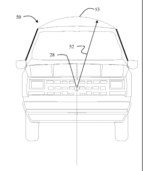
vehicle
(SUV) 2 shown in FIG. 1A and a passenger car 3 shown in FIG. lB have different
aspect ratios and therefore the roll radius 5 to the corners varies
considerably. The
radius from the Center of Mass (CoM) also varies to the various surfaces of
each
vehicle and is usually shorter to the top of the vehicle, represented by
radius 6, than to
the corners created by the sides and roof line, represented by radius 7.
[Para 3] The sequence of a rollover involves the vehicle moving laterally in
the
direction of travel, tipping towards the ground and contacting the roof rail
on the near
side (the first side to contact) and then contacting the second or far side
roof, then the
far side wheels, before continuing around to the near side wheels. The near
side
contact usually produces forces oriented into the near side pillars, limiting
the extent
of their deformation. The far side forces are typically more lateral and
therefore more
easily bend the pillars. Between the first near side contact at maximum
radius, the flat
of the roof can contact the ground. The CG falls towards the ground before
being
forced to rise as the far side corner with the larger radius rolls over the
ground. If the
roof is strong enough it does raise the CG, but if not, it collapses. The
difference
between the radii to the flat and the corner is a measure of the aggressivity
of the
structure.
[Para 4] Prior art rollover protection structures such as those disclosed in
US
patent nos. 3662177 issued to Notestine et al on November 23, 1971 or 4900058
issued to Hobrecht on February 13, 1990 which are designed for aftermarket
retrofit
1
CA 02735042 2011-02-22
WO 2010/022141 PCT/US2009/054293
on vehicles which may be more subject to rollover conditions such as four
wheel
drive vehicles, sport utility vehicles or pickup trucks employ geometric
designs that
require significant vertical structural elements that intrude into the cabin
or usable
space in the vehicle interior or must be affixed outside the normal outline of
the
vehicle to achieve the necessary support as disclosed in US Patent no. 7338112
issued
to Gilliland on March 4, 2008.
[Para 5] It is therefore desirable to maintain the rolling radius from the
corner
and across the flat which significantly reduces far side deformation.
Additionally, it
is desirable to support the roof at the major radius with a strongly cord
supported bow,
to transfer loads from side to side bringing the strength of pillars on both
sides into
play for each roof rail contact.
SUMMARY OF THE INVENTION
[Para 6] A vehicle geometry for rollover crush resistance is created by
determining a center of mass providing a roll axis and establishing a roof
line contact
surface spaced from the center of mass by a hoop radius substantially equal to
a major
radius of roof roll contact from the roll axis. The roof line contact surface
may be
established in original designs for vehicles as a monocoque structure or
provided as
an original equipment manufacture (OEM) item or retrofit structural assembly
using
an arcuate member shaped as a byte of the hoop radius, which is mounted
between
two side rails on a nominally flat roofline with additional structural
supports for the
arcuate member.
[Para 7] For a nominally flat roofed vehicle, the invention is employed as a
cap
establishing and maintaining a roof line contact surface spaced from the
center of
mass by a hoop radius substantially equal to a major radius of roll contact
from the
roll axis.
BRIEF DESCRIPTION OF THE DRAWINGS
[Para 8] The elements and features of the invention are further described with
respect to the detailed description herein and the following drawings wherein
[Para 9] FIG. 1A is a front view of a conventional sport utility vehicle
demonstrating the roll axis with the associated roll radius and radius from
the center
of mass (CoM);
[Para 10] FIG. lB is a front view of a conventional sedan showing roll axis,
roll
radius and radius from the CoM;
2
CA 02735042 2011-02-22
WO 2010/022141 PCT/US2009/054293
[Para 1 1 ] FIG. 2 is a front view of a conventional vehicle showing the major
and
minor radii;
[Para 1 2] FIG. 3 is a front view of the vehicle of FIG. 2A with a nominal
tripped
roll position;
[Para 1 3] FIG. 4 is a front view of the vehicle of FIG. 2A with a likely
tripped
roll contact position;
[Para 14] FIG. 5 is a front view of a vehicle incorporating a hoop radius
according to the present invention;
[Para 1 5] FIG. 6 is an isometric view of a rollover protection structure
(RPS)
implemented on an existing vehicle as either an original equipment
manufacturing or
aftermarket retrofit;
[Para 1 6] FIG. 7 is top view of the RPS of FIG. 6;
[Para 1 7] FIG. 8 is a side view of the RPS of FIG. 6;
[Para 1 8] FIG. 9 is an isometric view of a RPS with an additional hoop radius
support;
[Para 19] and
[Para 20] FIG. 10 is an isometric view of the RPS of FIG. 6 with a composite
wind deflector.
DETAILED DESCRIPTION OF THE INVENTION
[Para 21 ] When a conventional vehicle rolls, the distance from the roll axis
to the
closest portion of the roof is always less than the distance from the roll
axis to the roof
rails as shown in FIG. 2 for a conventional vehicle 20. These two radii are
known as
the major radius 22 and minor radius 23. When a vehicle rolls in a manner
which
would result in the roof panel becoming parallel and in contact with the
ground
(nominally at a roll angle 24 exceeding approximately 145 degrees as shown in
FIG.
3), the center of gravity 28 must be lifted by about the difference between
actual
radius of contact 23', nominally equal to the minor radius as shown for an
exemplary
roll contact angle 26 of about 185 degrees in FIG. 4, and the major radius in
order for
the vehicle to continue rolling without roof crush. The difference between the
major
and minor radii is defined for purposes of the present invention as a measure
of
geometric aggressivity. If the roof is strong enough to oppose this lifting
force
without deforming, the vehicle will continue to roll with little damage to the
roof
3
CA 02735042 2011-02-22
WO 2010/022141 PCT/US2009/054293
When the roof is too weak, it will deform rather than support the load needed
to lift
the vehicle.
[Para 22] The structural requirements to achieve the necessary strength are
directly proportional to the geometric shape of the roof exterior or contact
surface on
which the vehicle will roll. The present invention provides a range of
effective minor
radii for a geometry established for reduction in far side aggressivity in the
roll
contact surface for the vehicle thereby increasing the roll crush resistance
for a
vehicle 50 as shown in FIG. 5. The hoop radius 52 from the center of mass to a
roof
line 53 for optimum performance should preferably be equal to the major radius
within a range of +0 to 5% with ends faired to the side structure, nominally
the A
pillar profile, as shown in FIG. 5. The system is estimated to be reasonably
effective
with original or dynamically deforming radii of +10% and -5% with the ends
faired to
the side structure. There is some sensitivity to the matched radius in
minimizing the
forces on the far side which is estimated to be zero to 2 % less than the
corner.
[Para 23] A vehicle incorporating the geometry of the present invention in an
integral roof structure as the roll contact surface provides the benefit of a
monocoque
or semi-monocoque structure relying on the stressed skin of the roof as a
structural
element thus reducing the size and strength of the internal structural members
of the
vehicle frame to achieve the desired rollover crush resistance. Such a
monocoque
structure may in exemplary embodiments employ sheet metal skins with metal
ribs or
formers, or a fiberglass or other composite structure.
[Para 24] Original equipment manufacturing (OEM) of vehicles with the
geometric shape according to this invention can provide significant
improvement in
roll deformation resistance without significant increase in actual strength of
structural
members or conversely structural members having current strength for
conventional
vehicles will provide adequate structural strength to avoid deformation during
roll
which would not be possible with the current vehicle profiles. The embodiment
of the
geometry in OEM can be accomplished with standard welded production sheet
metal
construction adding little additional weight and cost while significantly
reducing (by
50% or more) the far side roof crush as compared to that resulting from the
original
design in the worst foreseeable planar rollover conditions.
[Para 25] Often product safety improvements are somewhat subordinated
features in sales materials to more evident and useful everyday purposes which
can be
4
CA 02735042 2011-02-22
WO 2010/022141 PCT/US2009/054293
accommodated as ancillary features with the geometry of the present invention
such
as a long built in storage place for skis, or additional stand-up aisle or
middle seat
head room or aerodynamically shaped lower drag for fuel economy, or round
shaped
side glazing for better skyward sightseeing.
[Para 26] Current design vehicles can be provided for by Original Equipment
Suppliers (OES) or retrofitted with a rollover protection structure (RPS) that
provides
the benefits of the geometry of the current invention with the beneficial roll
deformation resistance but without requiring the addition of significant
vertical
structural members as required in present RPS devices. As shown in FIGs. 6 -
9, the
RPS 60 includes an arcuate member 62, shaped as a byte of the hoop radius,
which is
mounted between two side rails 64, 66 on a nominally flat roofline 67. The
arcuate
member provides the roll contact surface at the designed hoop radius. The
arcuate
member is supported at an angle 68 relative to the roof by forward angled
supports 70
and rearward angled supports 72. Hoop radius 52 is also shown. A front lateral
member 74 extending between the side rails provides attachment for the forward
angled supports and a midships lateral member 76 between the side rails
provides
attachment for the rearward angled supports. In the embodiment shown, the
rearward
angled supports attach at a single boss 78. Forward diagonal surface members
80 and
82 extend from the intersection of the front lateral member and side rail to
the boss
and rearward diagonal surface members 84 and 86 extend from the boss to the
trailing
end points of the side rails. A rear lateral member 88 extends between the
trailing end
points of the side rails.
[Para 27] In the exemplary embodiment shown in the drawings, the RPS was
fabricated using 1.625 in. diameter steel tube with a wall thickness of 0.125
in. for the
arcuate member. Support structure for the side rails were fabricated from 1.0
in. by
2.0 in rectangular stock with a wall thickness of 0.125 while the angle
support
members employed 1.0 in by 1.0 in square tube with 0.125 in wall thickness.
All
elements used hot rolled steel with 26,000 psi strength.
[Para 28] The RPS provides a cap establishing and maintaining a roof line
contact surface spaced from the center of mass by a hoop radius substantially
equal to
a major radius of roll contact from the roll axis. The exemplary embodiments
have
employed steel for the arcuate member and other elements of the cap, however,
alternative embodiments employ cast, molded or composite materials of
sufficient
CA 02735042 2011-02-22
WO 2010/022141 PCT/US2009/054293
structural rigidity. Retrofit or production construction can be effected with
welded,
bolted and glued alternative materials such as high strength steel, aluminum,
fiberglass and carbon fiber sheets, as well as molded, formed or extruded
techniques.
[Para 29] While the geometry of the present invention reduces the structural
support requirements over prior art designs, performance in especially
hazardous
rollover conditions such as rugged terrain, military, paramilitary and
security forces
(like secret service armored SUVs), and in mining operations, it may be
necessary in
retrofit designs to provide protection beyond the capability of the geometry
and the
strength of the existing production supporting pillars. In such cases the
strength of the
additional roof structure will exceed the capability of the pillars and the
associated
embodiment of the present invention includes internal or external "buttresses"
reinforcing the joints between the "B-pillars" and the roof. There are at
least two
types, internal and external.
[Para 30] An exemplary internal structure is an inverted L-shaped bracket
bolted
to the B-pillars and to the roof structure through the roof rail. Although
minimally
intrusive, for diplomatic, ambassadorial and presidential purposes it may be
desirable
to provide the buttresses externally.
[Para 31 ] A special problem exists in certain four door vehicles in that the
front
door closes and latches on the B-pillar, while the rear door is hinged on the
B-pillar,
and both exterior door skins are close fitting along the vertical center line
of the B-
pillar. An exemplary external buttress solution is to drill two or more
approximately
1.25" holes through the external skin of the doors at the B-pillar centerline
and locate
and fasten 1" diameter stand-offs through those holes to the B-pillar. The
standoffs
are attached to each other by a rearward offset bar extending vertically and
bolted to
the roof structure. This bar is a truss to the B-pillar strengthening it,
attaching to the
roof structure and providing the clearance necessary for the doors to open
(the front
door opens out and clears the rearward biased bar, while the rear door opens
inward at
its forward edge).
[Para 32] In certain roll scenarios, if the vehicle center of gravity is
shifted aft
due to passenger loading or geometric design of the vehicle, roll contact may
occur on
the aft portion of the roof Additionally, the configuration of the vehicle,
relative CG
positioning and the actual tripping scenario inducing the roll may result in a
pitch
moment of inertia and associated radius of gyration which causes the vehicle
to
6
CA 02735042 2011-02-22
WO 2010/022141 PCT/US2009/054293
wobble like a football or roll on the aft portion of the roof As such the
placement of
the arcuate member longitudinally on the vehicle differing from the
embodiments
shown and described with respect to FIG. 6 or use of at least one additional
arcuate
member may be employed to assure that the hoop radius for the actual resulting
contact surface is maintained. This assures protection of passengers in all
seat
locations.
[Para 33] To accommodate dynamics resulting from such a roll with the major
and minor radii taken at a section in the aft portion of the vehicle, a second
hoop
radius is established at that section with an arcuate support as a byte
defined by that
radius to avoid roof crush at that location. In a view as shown in FIG. 9 a
second
arcuate member 62' is employed in a position near the C pillar for an extended
Sport
Utility Vehicle to accommodate a rearward CG shift of greater than 5%. Such
positioning provides protection for occupants of aft rows of seating in the
vehicle.
With a monocoque structure as previously described for such extended vehicles,
the
desired hoop radius is extended along the length of the monocoque roof to
achieve the
desired hoop radii at both a forward and aft roof position.
[Para 34] The RPS can additionally be fitted with a fiberglass wind deflector
90
as shown in FIG. 10 for enhanced aerodynamic performance. The deflector may
provide only a front shield as shown or a complete encapsulation of the RPS
structure.
The RPS structure as shown in FIGs. 6 or 9, with or without the deflector, may
include conventional roof rack elements for carrying luggage, bicycles or
other goods
and be supplied as an aftermarket kit to be added to a vehicle.
[Para 351 Having now described the invention in detail as required by the
patent
statutes, those skilled in the art will recognize modifications and
substitutions to the
specific embodiments disclosed herein. Such modifications are within the scope
and
intent of the present invention as defined in the following claims.
7