Note: Descriptions are shown in the official language in which they were submitted.
CA 02735068 2011-02-23
PCT/EP2009/060778
Translation (P27798)
1
Sandwich panel with integrated reinforcing structure and method for the
production
thereof
The invention relates to a sandwich panel with a core structure, in particular
with a
honeycomb-shaped core structure and plane-parallel cover layers applied on
both sides of
said core structure to form a floor surface in a fuselage airframe of an
aircraft. The fuselage
airframes of passenger aircraft are usually provided with at least one floor
frame which is
used, inter alia, for creating a walkable floor surface. The floor frame
consists of a plurality of
crossbars which are arranged in parallel behind one another and transversely
to the
direction of flight and are connected to annular formers of the fuselage
airframe structure. In
the longitudinal direction of the fuselage airframe, seat rail profiled parts
which are used for
attaching the passenger seats, inter alia, and also increase the rigidity of
the floor frame are
arranged on the crossbars in a mutually parallel spacing. Usually inserted
between the seat
rail profiled parts is a plurality of floor panels which are generally formed
by sandwich panels
approximately 1 cm thick. The floor panels have a generally honeycomb-shaped
core
structure which is overlaid on both sides by cover layers. The core structure
of the floor
panels is generally formed by Nomex paper, while the cover layers are
produced with a
fibre-reinforced plastics material such as, for example, a glass fibre-
reinforced phenol resin
or a carbon fibre-reinforced epoxy resin.
In order to meet passengers' increasing requirements in terms of comfort,
modern aircraft
are fitted with a plurality of sanitary facilities and wetrooms as well as
galley blocks which are
arranged, distributed through the passenger cabin. In the regions of the
sanitary and galley
facilities, heavy loads are applied which have to be absorbed by the floor
panels, that is to
say, the underlying floor frame, and transferred into the fuselage airframe
structure. The
galley and sanitary modules are usually connected to the floor frame by so-
called "hard
points" which allow the load to be transferred at selected points from the
module into the
underlying structure and additionally allow a tolerance compensation via the
connection.
According to the prior art, the galley, wetroom and sanitary modules are
attached to supports
which run under the floor panels and between two crossbars in the longitudinal
direction of
the aircraft. The "hard points" of the modules can be directly screwed, for
example, into
these supports.
However, where there is this type of attachment, changing the spatial position
of the
modules is only possible by making extensive modifications to the floor frame.
Thus, it is
CA 02735068 2011-02-23
PCT/EP2009/060778
Translation (P27798)
2
only possible to make changes specifically desired by the clients at a
considerably increased
constructive effort because the floor frame has to be adapted to the altered
cabin layout.
It is therefore the object of the invention to provide a sandwich panel onto
which a sanitary,
wetroom and/or galley module can be directly attached and the geometric
dimensions of
which, including the overall height, do not differ from the known standard
floor panels.
This object is achieved by a sandwich panel which has the features of claim 1.
Due to the fact that the core structure has at least one recess at least in
certain regions, into
which a reinforcing structure is integrated, it is possible for galley,
wetroom or sanitary
modules of a great weight to be directly attached to a sandwich panel
configured according
to the invention, without further supporting measures. The insertion of
additional supports
into the floor frame is unnecessary. Compared to the floor panels used as
standard, there is
no local thickening or elevation (bead).
Thus, the layout of the passenger cabin of the aircraft, in particular the
spatial positioning of
the sanitary and galley modules on the floor frame can be varied in a simple
and rapid
manner. Extensive constructive adaptations of the floor frame to the altered
position of the
modules are no longer necessary, since the sandwich panel according to the
invention can
be positioned in a locally variable and universal manner in all regions along
the floor frame.
The sandwich panel can therefore be positioned substantially freely in the
direction of flight,
i.e. parallel to the longitudinal axis (x-axis) of the aircraft.
The at least one reinforcing structure integrated locally into the core
structure reinforces the
core structure of the sandwich panel in particular such that forces which act
vertically and
parallel to the upper side of the panel can be absorbed.
A development of the sandwich panel provides that the at least one reinforcing
structure is
formed with at least one core.
In known sandwich panels, the main function of the core structure is to keep
the cover layers
in a fixed spacing from one another, while the actual load transfer takes
place by means of
the cover layers. As a result of directly integrating the reinforcing
structure into the core
structure, the sandwich panel according to the invention can also directly
absorb
compressive forces which act vertically to the panel surface.
CA 02735068 2011-02-23
PCT/EP2009/060778
Translation (P27798)
3
A further development of the sandwich panel allows for the core to be provided
at least in
certain regions with at least one strip which is formed using a prepreg
material, the
reinforcing fibres of which each have a uniform running direction of in
particular 45 .
This measure improves the mechanical strength of the core, in particular the
ability thereof to
transfer shearing forces.
The prepreg materials used are preferably narrow strips which have an
arrangement of
reinforcing fibres with, in each case, a uniform fibre run direction. A
plurality of these prepreg
strips which have alternating fibre orientations of + 45 and - 45 are wound
round the core
to achieve a high loading capacity mainly in the thrust direction. The prepreg
material
consists of reinforcing fibres which have been previously impregnated with a
curable plastics
material such as, for example, an epoxy resin, a polyester resin or a phenol
resin.
Reinforcing fibres include in particular carbon fibres, glass fibres and
aramid fibres. The
prepreg material is generally held ready on large rollers and can be easily
drawn off
therefrom, so that the core-wrapping operation can be automated and integrated
into
continuous production processes which are already available for sandwich
panels.
A further development of the invention allows for at least one reinforcing
structure to be
provided at least in certain regions with at least one two-dimensional blank,
said at least one
blank being formed by a prepreg material, the reinforcing fibres of which have
a running
direction of 0 and/or 90 .
This configuration means that the covered core can also be loaded by tensile
forces. In
principle, the core can be covered by any desired sequence of prepreg
materials with
running directions in each case of 45, 0 and 90 according to the
requirements of the
increased loading conditions provided for the sandwich panel (floor panel), as
long as the
shape of the core allows the preimpregnated reinforcing fibre layers to be
draped without
folds and laid without any gaps. The blanks of the prepreg material with a
fibre orientation of
0 or 90 can generally be laid on the core only in the direction of a
longitudinal or transverse
axis of the core due to the greater width, to avoid a distorted drape.
Alternatively, the blanks
can be positioned at least in certain regions on an upper side and/or a lower
side of the core,
leaving free the encircling edges.
A further configuration provides that the at least one reinforcing structure
can be introduced
in an interlocking manner at least in certain regions into the recess inside
the core structure,
and forms a material bond with the recess.
CA 02735068 2011-02-23
PCT/EP2009/060778
Translation (P27798)
4
This produces an effective transfer of force between the reinforcing structure
and the
surrounding sandwich panel. Due to the fact that the core is enwrapped by a
prepreg
material which has not yet cured, it does not necessarily have to be bonded
into the recess.
Alternatively however, the reinforcing structure can be bonded additionally
with the core
structure by a suitable adhesive. To further increase the strength, a filling
compound formed
using a curable plastics material can be introduced into a peripheral region
of the core
structure, i.e. into the closed-cell honeycomb which surrounds the reinforcing
structure. The
height of the reinforcing structure corresponds as exactly as possible to the
height of the
core structure of the rest of the sandwich panel, so that ideally, the
reinforcing structure is
embedded in the surrounding core structure of the sandwich panel in an almost
complete
interlocking fit and material bond, and thickenings (elevation due to bead
formation) are
avoided.
According to a further advantageous configuration of the sandwich panel, the
at least one
core is formed with a core structure, in particular with a honeycomb-shaped
core structure,
and/or with a rigid foam.
The use of a honeycomb-shaped core structure which is also used for the rest
of the
sandwich panel allows a simplified production process, since fewer starting
materials have to
be held in readiness. In a particularly advantageous manner, the core can be
formed with
the portion which has been cut out of the core structure, but in this case the
external
dimensions of the portion have to be reduced by an amount corresponding to a
material
thickness of the reinforcing layers which are to be laid later on. In this
respect, the superficial
shape of the core approximately corresponds to a superficial shape of the
recess inside the
core structure of the sandwich panel.
A further advantageous development of the sandwich panel provides that the
reinforcing
structure is formed by a combination of at least two reinforcing structures.
This configuration means that reinforcing structures with a complex
superficial shape can be
formed by combining at least two reinforcing structures with a simpler basic
shape. The
cores of these reinforcing structures with a simpler shape, taken separately,
can be covered
or enwrapped by the necessary reinforcing layers in a running direction which
is optimised in
terms of force flow. Furthermore, dividing a complex reinforcing structure
into a plurality of
reinforcing structures with a simpler shape makes it easier to drape the
prepreg strips over
the core without any folds.
CA 02735068 2011-02-23
PCT/EP2009/060778
Translation (P27798)
By combining, for example a cuboid core with a core which has a cuboid shape,
but with
inclined or bevelled trapezoidal side faces (so-called "obelisk"), it is
possible in a particularly
advantageous manner to construct a reinforcing structure for which the
occurrence of notch
stress is avoided as far as possible in the later sandwich panel. In general,
the recess will
have a rectangular shape.
A further advantageous configuration allows for the at least one reinforcing
structure to be
provided with at least one stopper, in particular a cylindrical stopper.
Inside the reinforcing structure, this measure provides an integration region
for a "hard
point", for example an insert, a bilateral screw-clamping piece or the like,
thereby enabling a
component, for example a galley module, to be directly mechanically attached
to the
sandwich panel. The stoppers are generally prefabricated. In the case of
cylindrical
stoppers, they are formed by a plurality of superimposed circular portions of
a fibre-
reinforced prepreg material which has not fully cured at the time of
processing. After the
reinforcing structure has been embedded or bonded into the core structure
which is initially
at least still open, and after applying the upper cover layer, the entire
arrangement including
the stoppers is cured all at the same moment by the application of pressure
and/or
temperature. The cylindrical stoppers have diameters of between 10 mm and 200
mm so
that corresponding recesses or holes can be provided in the reinforcing
structure. The
stoppers are then covered with the prepreg strips with the reinforcing fibre
layers at 45
and the web-shaped, generally rectangular blanks with the reinforcing fibre
layers at 00 or
90 .
Furthermore, the object according to the invention is achieved by a method in
accordance
with claim 11 for the production of a sandwich panel with a core structure, in
particular with a
honeycomb-shaped core structure which is provided on both sides with plane-
parallel cover
layers, in particular a sandwich panel according to claims 1 to 10, the method
comprising the
following steps:
a) introducing at least one recess into the core structure,
b) applying strips formed using a fibre-reinforced prepreg material to at
least one core to
form at least one reinforcing structure which can be introduced in an
interlocking
manner at least in certain regions into the at least one recess while creating
a
material bond,
CA 02735068 2011-02-23
PCT/EP2009/060778
Translation (P27798)
6
c) applying of the cover layers to both sides of the core structure, and
d) curing the at least one reinforcing structure and the cover layers by
applying
pressure and/or temperature.
Due to the fact that the at least one reinforcing structure is introduced into
a recess made
previously in the core structure before the cover layers are applied on both
sides of the core
structure, i.e. said reinforcing structure is introduced into the sandwich
panel which is still
open, it is possible to integrate the at least one reinforcing structure into
the sandwich panel.
If required, the reinforcing structure can be bonded into the recess. Due to
the flush
embedding, it is no longer necessary to change the standard overall height of
the sandwich
panel or to locally thicken the sandwich panel to increase the load-bearing
ability.
According to the method, in step a) first of all a recess is made in the core
structure, the
depth of which extends over the entire height of the core structure to achieve
a flush
termination of the reinforcing structure. The recess can have almost any
desired geometric
shape, but is usually in the shape of a cuboid with vertical and/or at least
two opposing,
bevelled or inclined edges. In the next step b), a plurality of reinforcing
layers consisting of a
strip-shaped prepreg material is laid onto the core. In this respect,
preferably at least two
different prepreg strips in each case with a different fibre orientation of +
45 or - 45 are
wound alternately onto the core.
The (supporting) core itself is formed for example from a rigid foam material.
Alternatively,
the core can also be produced from the same material which is used to form the
core
structure of the sandwich panel itself, i.e. for example, with a honeycomb-
shaped Nomex
paper. In addition, an upper side and/or a lower side of the core can be
covered with further
reinforcing fibre layers in which the reinforcing fibres preferably have a
running direction of
0 or 90 . The angle values in respect of the running direction of the
reinforcing fibres in the
prepreg strips relate in each case to an angle which exists between a
longitudinal axis of the
prepreg strip or their parallel outer edges and the respectively considered
longitudinal axis of
the reinforcing fibres. The lay or deposition angle at which the prepreg
strips are laid on the
core is to be distinguished therefrom. This angle which is determined between
the
longitudinal axis of the strip and a component edge is not constant and can
vary depending
on the lay site.
Thereafter, the core prepared thus is embedded in the recess in the core
structure of the
sandwich panel to achieve an interlocking and material bonding integration of
the reinforcing
structure.
CA 02735068 2011-02-23
PCT/EP2009/060778
Translation (P27798)
7
The regions, adjoining the core, of the surrounding core structure of the
sandwich panel can
be provided with a curable filling compound to improve the transfer of forces
from the
reinforcing structure into the core structure. The filling compound is
preferably formed using
a curable plastics material, for example, an epoxy resin, polyester resin or
phenol resin
which is optionally fibre-reinforced or stabilised in another way. In step c),
the cover layers
are applied to both sides of the core structure. The cover layers are
generally joined to the
core structure by a suitable adhesive. In the final step d), the entire
arrangement is cured.
Up until the end of step d), the reinforcing structure, the two cover layers
and the optional
filling compound are in an uncured, i.e. still ductile state.
Further advantageous embodiments of the method are set out in the further
claims.
In the drawings:
Fig. 1 is a plan view of a first, cuboid reinforcing structure with a core,
onto parts of
which reinforcing fibre layers have been applied,
Fig. 2 is a side view of the reinforcing structure according to Fig. 1 with a
second
reinforcing structure arranged vertically offset underneath, with an
approximately trapezoidal cross-sectional shape,
Fig. 3 is a plan view of a partial portion of a sandwich panel still open at
the top, with
the embedded reinforcing structure according to Fig. 2, and
Fig. 4 is a cross-sectional view through a cylindrical stopper with an
attachment
element (hard point) which can be accommodated therein.
In the drawings, the same constructive elements have the same reference
numerals in each
case.
Fig. 1 is a plan view of a first reinforcing structure which is provided to be
embedded into a
core structure of the sandwich panel according to the invention.
A first cuboid reinforcing structure 1 comprises, inter alia, a core 2 which
is formed with a
plurality of honeycomb-shaped cells (so-called "honeycomb") and around which a
plurality of
CA 02735068 2011-02-23
PCT/EP2009/060778
Translation (P27798)
8
strips 3 to 6 is wound. The core 2 has a cuboid shape, the side faces being
inwardly inclined
all round (bevelled at an angle of 45 ). The strips 3 to 6 are formed from a
curable, fibre-
reinforced prepreg material, the reinforcing fibres of which having different
running
directions. The strips 3 and 4 are formed by reinforcing fibres which have a
running direction
of - 45 , while the strips 5, 6 wound on top have a fibre running direction of
+ 45 . The strips
3 to 6 are covered or enwrapped by a web-shaped blank 7 which is likewise
formed from a
prepreg material. Unlike the strips 3 to 6, the reinforcing fibres in the
blank 7 have a running
direction of 00 and/or 90 .
Furthermore, a cylindrical stopper 8 with a diameter of 90 mm is introduced
into a central
region of the core 2. The cylindrical stopper 8 is formed by a plurality of
circular cutouts,
layered one on top of another and consisting of a fibre-reinforced prepreg
material. A height
of the stopper 8 approximately corresponds to a height of the core 2, to avoid
a bead
formation (i.e. thickening) of the sandwich panel. Inserted into the lateral
peripheral portions
of the reinforcing structure 1 are in each case three likewise cylindrical
stoppers with a
smaller diameter of approximately 19 mm, but with the same height as stopper
8, of which
only the two upper, opposing stoppers 9, 10 have been provided with a
reference numeral.
The stopper 8 is used for the later integration of an attachment element (cf.
in particular Fig.
4), particularly of a hard point, an insert, a screw-clamping piece or the
like, thereby
enabling, for example, a component to be attached by screwing to the sandwich
panel
according to the invention, while at the same time producing a tolerance
compensation.
Fig 2 is a side view of the cuboid reinforcing structure 1 according to Fig. 1
with a second
reinforcing structure shown underneath in a vertically offset position and
with a trapezoidal
cross-sectional shape.
This results in a more complex shape of the (entire) reinforcing structure, on
which
nevertheless the reinforcing fibre layers of the prepreg material to be laid
can be draped
ideally without any folds.
The strips 3 to 6 are guided around the outer edges of the core 2 and surround
it on all
sides. The same applies to the blanks 7.
The second reinforcing structure 11 is formed with a cuboid core 12.
Corresponding to the
first reinforcing structure 1, the core 12 is covered or enwrapped all round
by a plurality of
strips 13 to 16 and blanks 17 of a prepreg material with a fibre orientation
of 45 and 0
and/or 90 . The stopper 8 penetrates the two reinforcing structures which are
shown
vertically offset to one another merely to provide a better illustration.
CA 02735068 2011-02-23
PCT/EP20091060778
Translation (P27798)
9
Both reinforcing structures 1, 11 are combined into one reinforcing structure
18 and
integrated into a correspondingly configured recess (cf. Fig. 3) in a core
structure of a
sandwich panel to be produced.
The reinforcing structure 11, as shown in Fig. 2, is generally positioned
underneath the
reinforcing structure 1 in the recess of the core structure of the sandwich
panel, so that the
cuboid, first reinforcing structure 1 rests on one side against the upper
cover layer of the
sandwich panel, while the second reinforcing structure 11 with the trapezoidal
cross-
sectional shape rests against the lower cover layer with its shorter lower
side and rests
against the cuboid reinforcing structure 1 with its longer upper side.
The two reinforcing structures 1, 11 form an (entire) reinforcing structure
18, the second
trapezoidal reinforcing structure 11 minimising notch stresses in the later
sandwich panel.
Furthermore, the prepreg materials can be draped or laid more easily around
the separated
reinforcing structures.
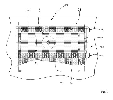
Fig. 3 shows a plan view of a detail of a sandwich panel which is still open
at the top and has
an embedded reinforcing structure.
A sandwich panel 19 with a core structure 20 is already provided on the lower
side with a
cover layer 21 but upwardly has not yet been closed by an upper cover layer.
The complex
reinforcing structure 18 formed by combining the first and second reinforcing
structures 1, 11
is inserted into a recess 22. Since both reinforcing structures 1, 11 are
enwrapped by
adhesively acting, initially not yet cured prepreg materials, an additional
adhesive bonding is
not generally required. The recess 22 is configured such that it exactly fits
the superficial
shape of the reinforcing structure 18, to achieve an interlocking and material-
locking
(adhesive) integration, free from possible gaps or cavities which would reduce
the
mechanical loading capacity of the finished sandwich panel. In this respect,
it is very
important that the height of the reinforcing structure 18 to be integrated
corresponds as
exactly as possible to the height of the core structure 20 used, in order to
avoid undesirable
thickenings or local elevations of the sandwich panel 19. As a result, there
is an
"interlocking" bonding between the reinforcing structure 18 and the core 2
surrounding said
reinforcing structure 18 along the edges.
Furthermore, the illustration of Fig. 3 shows the upper blank 7 formed by a
web-shaped
prepreg material which is constructed with reinforcing materials with a fibre
orientation of 0
- and/or 90 . In a region 23 in which the core structure 20 adjoins the
reinforcing structure
18, a suitable filling compound 24 is introduced at least into certain regions
of the core
CA 02735068 2011-02-23
PCT/EP2009/060778
Translation (P27798)
structure 20 or into the honeycombs thereof. The filling compound is
preferably formed by a
curable plastics material which is provided, if appropriate, with a
reinforcement to
mechanically strengthen the material. Furthermore, the stopper 8 is indicated
by a dashed
line, since it is completely covered by the blank 7.
Fig. 4 is a cross-sectional view through the sandwich panel with cover layers
applied to both
sides in the region of the large-area, central stopper (cf. Fig. 3).
The sandwich panel 19 is provided with the cover layers 21, 25. The
reinforcing structure 18
with the stopper 8 inserted therein is located between the cover layers 21,
25. A stepped
hole 26 used for integrating or attaching an attachment means 27 is introduced
into the
stopper 8. The attachment means 27 comprises two sleeves 28, 29 which are to
be
connected together. The sleeves 28, 29 can be connected together, for example,
by a
combined screw-clamping connection. The sleeve 28 on the left-hand side has a
tapped
hole 30 into which a screw bolt (not shown) can be screwed to connect a
further component,
for example, a galley module.
As a result of the reinforcing structure 18 which is integrated according to
the invention into
the core structure 20, the sandwich panel 19 has a high load bearing ability
while its outer
geometric dimensions remain unchanged compared to the standard dimensions of
the
sandwich panels usually used as floor panels.
To carry out the method according to the invention, in a first step a), at
least one recess 22 is
made in the core structure 20 of the sandwich panel 19 to be formed. The
recess 22 is to be
made as precisely as possible to ensure an integration, which is ideally
interlocking and
material-locking, of the at least one reinforcing structure 1, 11, 18. The
recess 22 can be
made using, for example, a CNC-controlled milling machine. In principle, it is
possible to use
the worked cutout to form the recess 22 as a core for the later reinforcing
structure 1, 11, 18.
Recesses or holes for receiving stoppers can then be made in the prepared
cores 2, 12. The
stoppers are formed using a plurality of superimposed cutout layers of a
prepreg material
which is initially still soft and the stoppers have, for example, a
cylindrical shape with a
diameter of between 10 mm and 200 mm.
In a further step b), a plurality of strips 3 to 6, 13 to 16 which are each
formed using a fibre-
reinforced prepreg material, are wound onto a core 2, 12. These cores 2, 12
can be formed
using, for example, a rigid foam or a core structure material which
corresponds to the
material used to provide the core structure 20 of the sandwich panel 19. In
the laying
CA 02735068 2011-02-23
PCT/EP2009/060778
Translation (P27798)
11
process, strips with a fibre orientation of + 45 and strips with a fibre
orientation of - 45 are
alternately laid down around the core 2, 12 in a plurality of windings.
Finally, blanks 7 of a
prepreg material with a fibre orientation of 0 - and/or 90 - are laid on the
core 2, 12. The
core 2, 12 is ideally completely surrounded by the prepreg material.
Thereafter, the prepared
reinforcing structure 1, 11, 18 is introduced into the recess 22. Regions of
the core structure
20 adjoining the reinforcing structure 1, 11, 18, i.e. the associated
honeycombs can
optionally be filled with a filling compound consisting of a curable plastics
material to improve
the connection. For example, a strip of the core structure 20 which surrounds
the embedded
reinforcing structure 1, 11, 18 and has a width of up to 2.0 cm is filled as
completely as
possible with a curable filling compound. The reinforcing structure 1, 11, 18
can optionally
also be adhesively bonded therein.
In the following step c), the cover layers 21, 25 are applied to both sides of
the core structure
20. In the final step d), the entire structure is cured by applying pressure
and/or temperature
in suitable devices, for example, a furnace or an autoclave. In principle, it
is possible to
provide one side of the core structure 20 with a cover layer 21, 25 before the
recess 22 is
made in the core structure 20.
After the curing procedure in step d), holes or stepped holes are made in the
stoppers to
receive attachment elements for connecting further components to the sandwich
panel.
Possible examples of attachment elements include inserts or clamping-screw
sleeves which
can be fastened in the holes in cured stoppers.
CA 02735068 2011-02-23
PCT/EP2009/060778
Translation (P27798)
12
List of reference numerals
1 (first) reinforcing structure
2 core (honeycomb cells)
3 strip (prepreg material, fibre orientation of - 45 )
4 strip (prepreg material, fibre orientation of - 45 )
strip (prepreg material, fibre orientation of + 45 )
6 strip (prepreg material, fibre orientation of + 45 )
7 blank (prepreg material, fibre orientation of 0 / 900)
8 stopper (large)
9 stopper (small)
stopper (small)
11 (second) reinforcing structure
12 core (honeycomb cells)
13 strip (prepreg material, fibre orientation of - 45 )
14 strip (prepreg material, fibre orientation of - 45 )
strip (prepreg material, fibre orientation of + 45 )
16 strip (prepreg material, fibre orientation of + 45 )
17 blank (prepreg material, fibre orientation of 0 / 90 )
18 reinforcing structure (combined)
19 sandwich panel (floor panel)
core structure
21 (first) cover layer
22 recess
23 region
24 filling compound
(second) cover layer
26 stepped hole
27 attachment means
28 sleeve
29 sleeve
tapped hole