Note: Descriptions are shown in the official language in which they were submitted.
CA 02735303 2011-02-25
WO 2010/025008 PCT/US2009/052669
GUIDED ROTARY FILE AS WELL AS APPARATUS FOR AND METHOD OF DEBURRING USING SUCH
A FILE.
BACKGROUND OF THE INVENTION.-
100011 This invention relates, generally to anach.ine tooling and more
particularly to
apparatus and methods for debarring operation'ns.
10002.1 Currently many machined fe ataa.res_ such as those found on aircraft
engine
parts, are debarred manually. This leads to inconsistencies in the finished
feature size acrd
shaape. With the introduction of requirements for stricter process control,
highly stressed
features require automated clel iaz in 7 processes to ensure consistency.
Because of the
difficult v machining aviation. materials- ma aye of these. features come out
of the, primary
machining operations with largge burrs that must be removed with carbide
canters (e.g.
rotary files).t'he difficulty with auÃomatin<gg these processes is removing
the burr without
removing parent mYaaterial. The burr size varies from part to part and the
location of the
feature can also vary making it impossible to program a specific toolpath to
remove e only
the burr.
100031 The state of the art for this application is to use an automated probe
to
determine the contours of the machined feature and then through adaptive
machining
morph an existing CNC toolpath to cause a deburring tool to follow the feature
and
remove the burr. Unfortunately this it is a very costly solution which
requires additional
maintenance support. It can also be vier difficult at times to probe the
feature without
probing the burrs, causing errors in the, toolpaath.
BRIEF SUNMARY OF THE INVENTION
10004 These and other shortcomings of the prior art are addressed by the
present
invention, which provides a rotary file having a guide pilot which permits
deluding
Without complex l ao .i aura ai.ar~ procedures.
[0005] According to one aspect of the invention, a rotary file includes:. (a)
a body
hay. n,_, first aand second ends, and an outer surfiace comprising a:t least
one cutting edge;
(b) a shank extending from the first end of the body which. is adapted to be
mounted in a
-l-
CA 02735303 2011-02-25
WO 2010/025008 PCT/US2009/052669
rotary tool; and (c:) a pilot extending from the second end of the bod , the
pilot defining,
an annular peripheral surface with an arcuate cross-section.
(OOOt>.[ According to another aspect of the invention, an apparatus is
provided for
.removing one or z Ãore burrs from a perip.h ral edge of a rt rchirÃed feature
isn a. workpicce.
including : (a) a debuÃri.aag, tool having a. rotatable spindle which is
resilieÃiiy deflectable
away from a nominal axis of rotation; (b) a rotar file. comprising: (i) a
body' having first
and second ends, and an outer surface compiisirw at least one cuttin ;edge-l
(ii) a shank
extending from the first end of the body which is mounted. in the spindle; and
(iii) a pilot
extending from the second end of the body, the pilot defining an annular
peripheral
surface with an arcuate cross-section,
[0007]1 According to another aspect of the invention., a method is provided
for
removing one or more burrs from a peripheral edge of a machined feature in a
vorkpiece,
The method includes: (a) providing a debarring tool has i.ng a rotatable
spindle which is
resiliently deflectable away from a nominal axis of rotation; (b) mounting a
rotaÃ- file in
the spindlen the rotary file comprising (i) a body haying first and second
ends, and an
outer surface comprising at least one cutting edge: (ii) a shank extending
from the first
end of the body which is mounted in the spindle-, and (iii) a pilot extending
from the
second end of the body, the pilot defining an annular peripheral surface with
an arcuate
cross-section; and (c) spinning the rotary file while simultaneously
traversing the rotar y
file along a preprograa macd toolpath., such that the pilot contacts a first
portion of the
a, orkpiece while the body cuts the one or more burrs. The toolpadl is
programmed to
r aaintain the spindle in a later ills, deflected position throughout the
debarring procedure
BRIEF DESCRIPTION OFJ'HE DRAWINGS
[000$) The invention may be best understood bs; reference to the following
description taken in conjunction with the accompanying drawing figures in
w0ich:
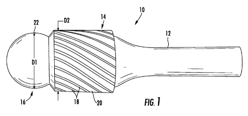
10009*1 Figure I is a side view of a rotary file constructed according to an
aspect of
the present invent:ion:.
100101 Figure 2 is in end view of the rota file of Figure
CA 02735303 2011-02-25
WO 2010/025008 PCT/US2009/052669
1.00.1.11 Figure 3 as a side view of an alterative rotary bale:
100121 Figure 4 is a side view of another alternative rotary file-
100.13-1 Figure 5 is a side view of another alterative rotary .file:
10014-1 Figure 6 is a side view of vet mother alternative rotas file;
10015 Figure 7 is as perspective view of a debarring tool with a guided rotary
file
loaded therein,
1.00161 Figure 8 is a perspectit e view of a . orkpiece azith a 1-eature m
achiared therein
before a deburring operation:
[017[ Figure 9 is a perspective view of the i vorkp.iece ofFigarre 6 with a
rotary file
performing as deburring operation thereon:
[00181 Figure 10 is a. cross-sectional view of a workpiece with a rotary file
adjacent
thereto-
(00191 Figure 11 is a cross-section a iewww of a wwworkpiece with a rotary
file engaged
therewith; and
(434320] Figure 12 is a perspective view of the work-piece of Fi<gure $ after
the
completion of the debarring operation.
DETAILED DESCRIPTION OFTHE INVENTION
(002.1.1 Referring to the drawings i.vherein identical reference numerals
denote the
same elements throu Phout the various views, Figures 1 and 2 depict. aa. rotas
file 10
constructed accordia gg to an aspect of the present in :enntionn. 'I he rotary
file 10 comprises
a shank 12, a body 14. and a pilot 1_t . 1'he rotary file 10 may be made from
a number of
krro,zn processes such as casting, forging, machining from billet stock, etc.
Typically the
rotary file 143 would be a single integral structure, but it could be built
up. for example
from components brazed or welded together. Norilirniting examples ofsuait able
materials
for the rotaa b the 10 include tool steels, trnLsten carbide- mid the like.
-3-
CA 02735303 2011-02-25
WO 2010/025008 PCT/US2009/052669
à 022 The shank 12 may be cylindrical as shorn, or may incorporate retention
and/or drive features of a known type, such as a machine taper, threads, or
one or more
fiats, ftrcets. or tabs (Dot shown.
[ 00231 The body .14 includes an array ofrutting lands 18 separated by flute
20. In
the illustrated example the cutting lands 18 have :r. conventional file tooth
profile;
however a different cutting profile or spacing may be used for the. lands 1
1004:1 The pilot 16 includes at least one peripheral surface 22 with an
arcuate cross-
section. The purpose of the arcuate shape is to allow the rotary file 10 to
contact a
wt>rpiece at va1`1'oos angles, as described in more detail below. In the
example shown D
Figure 1.7 the peripheral surface 22 defines a nearly complete sphere which
intersects the
body, 11 Figure 3 illustrates an alternative rotary file 110 having a pilot
116 which has ari
annular peripheral surface 122,,itl an arcuate cross-section that is bounded
by a flat end
C ace, 124.
100251 The dimensions of the pilot 16, in particular the overall diameter, may
vary, to
suit a ptrrticrrlrr application. Irr Fig
1. the pilot 16 is illustrated with a first outside
diameter "D I " that is slightly less than the outside diameter "D2" of the
body 14. Figure
4 illustrates another rot rra file, 210 with a pilot 216 having a. diameter "M
)" that is greater
than the diameter "W" of the body 214.
1Ã3026( Optionally., the pilot 16, or at least the peripheral surface 22, may
Incorporate
an anti friction surface. For example., it may he hardened and r
ricropolished..
Alierrratively, an anti-friction coating such as polytetraflrrorothey"lene
f(PTFE')s'Titaniurn
Nitride. Titanium Altai inum Nitride, Aluminum Nitride or other coatings
applied to
traditional metal cutting tools may be applied thereto.
1100271 The pilot may also be attached to the body by means of a threaded
fastener.
The pilot body 319 may be constructed from a. n Iaterial that is low friction
and is not
likely to mar a metallic workpiece, such as hard rubber or plastic. This 2
piece
construction method r nay also he used so as to increase the produrcability of
the tool.
[Ã 0281 As another example of a separate pilot construction, figure 6
illustrates an
-4-
CA 02735303 2011-02-25
WO 2010/025008 PCT/US2009/052669
alternative rotary file 410 having a pilot 416, shank 412, and body 41A The
pilot 416
comprises a bearing 11$ whose outer race defines an annular peripheral surface
422 as
described above. The be a.ri.ng 418 is secured to a stud 424 that protrudes
from the body
41.4, for example t-A., a friction or shrink fit, or . ith an adhesive or
threaded fastener. In
the illustrated e xarrmple the bearing 422 is of a conventional rolling-
element type.
[00291 As shown in Figure 7. the rotary file 10 ma-v be used in con unction
with a
conventional dehurring tool 24 comprising a rotary motor 26 (in this case, an
air motor)
having a compliant rotary spindle :28 with a collet 30 that receives the shank
121 ofthe
rotary file 10, The debcrrring tool 24 is carried by a manipulator arm 32
which is part of
an industrial robot of a known type, or by another suitable positioning
mechanism, While
not illustrated in det ri.l,, it will be understood that the manipulator arm
>2 is equipped to
move_ i.e. translate andfor rotate, the deburring tool 24 through multiple
degrees of
freedom. so as to cause the spindle 28 to follow a pre-programmed toolpath.
[0030[ The spindle 28 is "radially compliant," in other words, the spindle 2$
is
supported so it can pivot a\. <ay from a nominal rotational axis A of the
rotary motor 26 to
which it is attached, when a radially-directed force or "side: force" is
applied thereto. A
restoring force is provided to urge the spindle 29 towards the nominal or
centered
position when no side for ce is applied,
[003* 11 One example of a sui table deburring tool 24 is a model RC .I L.1
.`iDEBURR
device available from Al] Industrial Automation, Apex., NC 27539, USA. In this
particular device, the restoringq force is provided b A: a pneumatically
operated r rechanism.
For example when about 1.041 bar (15-60 psi) is provided to the debarring tool
24,, the
resulting restoring force will be about 12.7-42 N (2.8-9.5 lbs.), measured at
the collet 30,
In operation. the restoring force of the spindle 28 will be varied to suit a
particular
application. The restoring force is set to avalue which is high enough such
that any burrs
or chips will he effectively machined away from a \.vorkpiece feature. If the
restoring
force is too low, the rotary file 10 will tend to "ride over" those features
rather than
.
cutting them away
[0032[ Figure 8 shows a portion of a w orlcpiece W, having a. feature h
machined
eye
CA 02735303 2011-02-25
WO 2010/025008 PCT/US2009/052669
therein, such as a. slot or . roove. The .ffeature has a peripheral wall "P
that intersects the
outer surface of the w :orppiece W at a peripheral edge "E", One or more burrs
B extend
from the peripheral edge F. These burrs B are a.naturaa.l consequence ofknovvn
machi.n. n
processes.
Figure 9 shows the rotary file 10 in operation, removing a burr from the
feature Fin the
wwworkpiece W. T h.e spindle 28 is rotated at high speed (for example about
30,000 ltf M)
and moved. i,e. translated in a direction lateral to the rotational axis R of
the spindle 2 ,
in a programmed toolpath. The programmed toolpath is based on the nominal
geometry
of the feature and generally follows the peripheral wall 1', It is independent
of the
specific geometry of the burrs B (vhich is unknown). The toolpath first causes
the rotas;
file 10 to enter the open portion of the feature F. Then, as shown in Figure
110, the,
toolpath positions the rotary file 10 with a fixed amount of lateral
interference or ofset_.
denoted "O", from the peripheral surface 1' to the peripheral surface 22 of
the pilot. 16.
The amount of offset "O as selected to be large enough to ensure constant
contact of the
pilot 16 with the peripheral surface P. One example of a suitable offset
dimension 0,
,when using a rotarnfile 10 wits a body 12 having an outside di an ete.r of
about 9.53 mm
(0.375 in,), is about 3.18 rum (0.125 in.) to about 6.25 inni (0.25 in)_ With
the
programmed offset 0 , the toolpa.th causes the spindle 28 to be in a deflected
or
compliant position during the entire time the debarring} process is taking
place. The
contact between the pilot 16 and the periphea al surface P prevents the rota s
file 10 f:rorn
cutting deeper into the t-vorl piccc W. the result being that only the burrs B
are removed.
Figure 12 shows the finished workplece W,
[00331 Optionally, the rota y file 10 ma, be wised to machine a "prebreak" or
chamfer
into the peripheral edge` E. as well as .removing burrs B. This may be done by
deflecting
or angling therotary fr l e 10 more in relation to the wvorkpi ece than would
be the case for
a pure deburring operation. This process may be accommodated by making the
pilot
diameter subs Unit] alI v larger than that of the body. as shown in Figure 4.
The larger pilot
allow the deflection to be made without the edge of the flutes cutting a
coun.terhore
instead of a chamfer,
1Ã 0 4,1 Using the rotary file, 1.0 and the process described above, a
orkpieces W can
-6-
CA 02735303 2011-02-25
WO 2010/025008 PCT/US2009/052669
debarred consistently. This allows a toolpath to he programmed with reference
to
individual machined features to remove hrthTS without fear of overmachining or
leaving
some of the burr behind. Accordirx#YI '. t-1-10 cons. stenCy of an automated
process is
achieved without requiring excessive time in probing and setup procedures.
[OO3S 1 The foregoing has described a.rotary file rind a method for its use.
While specific
embodiments of the present invention have been described, it will be apparent
to those
skilled in the art that various modifications thereto can be madewithout
departing from
the spirit and scope of the invention- Accordingly, the Coregoing description
of the
preferred embodiment of the invention and the best mode for practicing the
invention are
provided for the purpose of ill ustration only and not for the purpose of
limitation.
-7-