Note: Descriptions are shown in the official language in which they were submitted.
CA 02735528 2011-02-28
WO 2010/030485 PCT/US2009/054476
DEVICE FOR OCCLUDING VASCULAR DEFECTS
BACKGROUND OF THE INVENTION
1. Field of the Invention:
The present invention relates to medical devices and associated methods for
treating
various target sites and, in particular, to medical devices having a multi-
layer structure, wherein
at least a portion of one of the layers includes a polymeric material.
II. Description of the Related Art:
A wide variety of intracardiac prosthetic devices are used in various medical
procedures.
For example, certain intravascular devices, such as catheters and guide wires,
are generally used
to deliver fluids or other medical devices to specific locations within the
vascular system of a
patient, such as a selective coronary artery. Other devices are used in
treating specific conditions,
such as devices used in removing vascular occlusions or for treating septal
defects and the like.
For example, devices have been developed for treating abnormalities, such as
an Atrial Septal
Defect (ASD), a Ventricular Septal Defect (VSD), a Patent Ductus Arteriosus
(PDA), a Patent
Foramen Ovale (PFO), as well as conditions that result from previous medical
procedures such
as Para-Valvular Leaks (PVL) following surgical valve repair or replacement.
However, the ability to deliver these devices to particular areas of the
vasculature or for
particular patients may be limited by their bulkiness. Previous devices
typically require a 14-16
French introducing catheter, which generally makes it impossible to treat
children affected with
congenital defects with these devices. With respect to a PDA, a smaller, lower
profile device
that can fit through a 4 French catheter potentially allows treatment of pre-
mature infants with a
PDA. Moreover, some of these devices are used to occlude a patient's vessel or
abnormality,
such as to stop blood flow through an artery to a tumor or other lesion.
Despite the general
ability to occlude a vessel or abnormality, reducing the time needed to
occlude the vessel or
abnormality is desired so that the device may be accurately and effectively
positioned and fixated
within the vessel.
Accordingly, it would be advantageous to provide a reliable occlusion device
which is
both easy to deploy through a catheter having a reduced diameter and that can
be accurately
placed in a vessel or an organ. It would also be desirable to provide a low-
profile recoverable
device for deployment in a vessel or an organ of a patient's body. In
addition, there exists a need
1
CA 02735528 2011-02-28
WO 2010/030485 PCT/US2009/054476
for a collapsible medical device for occluding abnormal openings in an vessel
or organ which
provides rapid occlusion following delivery and placement thereof. Moreover,
there is also a
need for an occlusion device that may be effectively fixated within a vessel
or an organ.
SUMMARY OF THE INVENTION
The above and other needs may be met by embodiments of the present invention
which,
in one embodiment, provides medical devices and methods for treating various
target sites within
the body. For example, a multi-layer occluder for treating a target site
within the body is
provided. The occluder may include coupled first and second layers. For
example, the first and
second layers may be disposed radially within one another, in either a
concentric or non-
concentric relationship. The first layer may include braided strands of
metallic material, and the
second layer may include braided strands of polymeric material, where "strand"
includes, but is
not limited to, a filament, a cord, a yarn, and/or a cable. At least one of
the first or second layers
may be configured to facilitate thrombosis.
The metallic material may include a shape memory or super-elastic alloy. The
polymeric
material may include polyester, polyolefin, polyamide, polysulphonate,
polycarbonate, and/or
polyurethane. The polymeric material may include a heat-settable polymer, such
as a shape
memory polymer, or a non-heat set polymer.
The first and second layers may be configured to be cooperatively
constrainable to a
common reduced shape through the application of external force and to
subsequently
cooperatively assume a common expanded shape when the external force is
removed. For
example, the first and second layers may respectively comprise strands braided
at a common
pitch, such that the first and second layers retain a substantially similar
length-to-diameter ratio
when axially elongated to the reduced shape.
In some embodiments, the second layer may include strands of metallic material
braided
or twisted with the strands of polymeric material. The metallic material of
the second layer may
be, but is not limited to, any of the metals mentioned previously as possible
constituent materials
for the first layer, but the composition of the metallic strands of the second
layer need not be the
same as the composition of the metallic strands of the first layer. The
strands of metallic
material of the first and second layers may have different diameters .
An elastomeric coating may be included, the coating acting to link cross-over
points of
2
CA 02735528 2011-02-28
WO 2010/030485 PCT/US2009/054476
the respective strands of the second layer. The elastomeric coating may be
constrainable to a
reduced shape through the application of external force, and may be configured
to subsequently
assume an expanded shape when the external force is removed.
A fastener may couple the first and second layers. For example, one or more
end clamps
may be employed to secure the braided strands of the first and second layers.
Alternatively, or
additionally, sutures and/or an elastic adhesive may couple the first and
second layers.
In some embodiments, the first layer may be disposed radially within the
second layer,
and the second layer may be disposed radially within a third layer. The third
layer is configured
to be constrainable to a reduced shape through the application of external
force and to
subsequently assume, when the external force is removed, an expanded shape
having at least a
portion similar to the expanded shape of the first layer. The metallic strand
densities and/or
strand diameters of the metallic material of the first and third layers may be
different from one
another.
In another aspect, a method for fabricating a multi-layer occluder is
provided. The
method includes providing a first layer comprising braided strands of metallic
material. The first
layer can be heat set in an expanded shape. A second layer can be provided
that includes braided
strands of polymeric material. The second layer may be coupled to the first
layer, for example,
by disposing the second tubular layer generally radially within or around the
first tubular layer.
The second layer may be heat set in an expanded shape similar to the expanded
shape of the first
layer, for example, by coating the second layer with a liquid elastomeric
material and curing the
elastomeric material while fixing the second layer in the expanded shape.
In some embodiments, a third layer comprising braided strands of metallic
material may
be provided, and the second layer may be positioned between the first and
third layers. The first
and third layers may be respectively braided over first and second mandrels
having different
diameters. The third layer may be heat set in an expanded shape having at
least a portion similar
to the expanded shape of the first layer.
In yet another aspect, a method of delivering an occluder to a target site
within the body
is provided. The method includes providing an occluder having a first layer
including braided
strands of metallic material and a second layer coupled to the first layer and
comprising braided
strands of polymeric material. The first and/or second layers may have a
preset expanded shape.
The occluder may be constrained to a reduced shape, for example, by axially
elongating the
3
CA 02735528 2011-02-28
WO 2010/030485 PCT/US2009/054476
occluder, and positioned, once constrained, in a catheter. The occluder can be
delivered to the
target site and deployed from the catheter such that the occluder assumes the
preset expanded
shape.
In still another aspect, a multi-layer medical device for treating a target
site within the
body is provided. The medical device includes a first layer comprising braided
strands of a first
metallic material. A second layer is coupled to the first layer and includes
braided respective
strands of polymeric and a second metallic material. In some embodiments, the
first layer may
be disposed radially within the second layer, and the first layer may be
disposed radially within a
second layer.
In yet another aspect, a medical device for treating a target site within the
body is
provided. The medical device includes a structure having braided strands of
metallic material.
At least one strand of polymeric material may be disposed spirally around and
adjacent to the
structure, for example, by being continuously in contact with a radially
exterior surface of the
structure. The braided strands may be configured to have a braid pitch and the
polymeric strand
may form a spiral configured to have a substantially similar braid pitch. In
some embodiments,
the structure may include a braided tube having a longitudinal axis, and the
polymeric strand can
spiral around the longitudinal axis.
BRIEF DESCRIPTION OF THE DRAWINGS
The foregoing features and advantages of the invention will become apparent to
those
skilled in the art from the following detailed description of a preferred
embodiment, especially
when considered in conjunction with the accompanying drawings in which like
numerals in the
several views refer to corresponding parts.
FIG. 1 is an enlarged, side elevation view of an occluder device according to
one
embodiment of the present invention;
FIG. 2 is an enlarged front elevation view of the device of FIG. 1;
FIG. 3 is an enlarged side elevation view of the device of FIG. 1 when
longitudinally
stretched;
FIG. 4 is a right end view of the device shown in FIG. 3;
FIG. 5 is an enlarged, side elevation view of an occluder device according to
an
embodiment of the present invention;
4
CA 02735528 2011-02-28
WO 2010/030485 PCT/US2009/054476
FIG. 6 is a right end view of the device of FIG. 5;
FIG. 7 is a enlarged view like that of FIG. 6;
FIG. 8 shows a multi-layered vascular plug according to an embodiment of the
present invention;
FIG. 9 shows the plug of FIG. 8 in combination with a center clamp;
FIG. 10 shows an alternative occluder device according to an additional
embodiment
of the present invention;
FIGS. 1la-l if are side and end views and cross-sectional views of an occluder
device
according to alternative embodiment for treating a vascular abnormality;
FIGS. 12a-12f show variations of occluder devices according to additional
embodiments of the present invention;
FIG. 13a is an example of a PVL anatomy;
FIGS. 13b-h illustrate various occluder devices for treating vascular
abnormalities
according to various embodiments of the present invention;
FIGS. 14a-14c are views of an occluder device according to a further
embodiment of
the present invention;
FIG. 15 depicts an embodiment of an occluder device wherein an inner braid
fills an
outer braid volume;
FIGS. 16a-16d are views of an occluder device according to alternative
embodiments
of the present invention;
FIG. 17 is an exploded perspective view of a medical device according to
another
embodiment of the present invention;
FIG. 18 is a perspective view of a medical device configured in accordance
with another
embodiment of the present invention;
FIG. 18A is a cross-sectional view of the medical device of FIG. 18;
FIG. 19 is an exploded perspective view of the medical device of FIG. 18;
FIG. 19A is a magnified view of a portion of the medical device shown in FIG.
19; and
FIG. 20 shows a braided fabric according to one embodiment of the present
invention.
DETAILED DESCRIPTION OF THE PREFERRED EMBODIMENTS
The present invention now will be described more fully hereinafter with
reference to the
5
CA 02735528 2011-02-28
WO 2010/030485 PCT/US2009/054476
accompanying drawings, in which some, but not all embodiments of the
inventions are shown.
Indeed, these inventions may be embodied in many different forms and should
not be construed
as limited to the embodiments set forth herein; rather, these embodiments are
provided so that
this disclosure will satisfy applicable legal requirements. Like numbers refer
to like elements
throughout.
Embodiments of the present invention provide an occlusion device for use in
occluding
an abnormality in a patients' body, such as an Atrial Septal Defect (ASD), a
Ventricular Septal
Defect (VSD), a Patent Ductus Arteriosus (PDA), a Patent Foramen Ovale (PFO),
conditions that
result from previous medical procedures such as Para-Valvular Leaks (PVL)
following surgical
valve repair or replacement, and the like. The device may also be used as a
flow restrictor or an
aneurysm bridge or other type of occluder for placement in the vascular
system. It is understood
that the use of the term "abnormality" is not meant to be limiting, as the
device may be
configured to occlude any vessel, organ, opening, chamber, channel, hole,
cavity, or the like,
located anywhere in the body.
According to one embodiment of the present invention for forming a
medical.device of
the invention, the device includes a braided fabric formed of a plurality of
wire strands having a
predetermined relative orientation with respect to one another. However, it is
understood that
according to additional embodiments of the present invention, the device may
be formed using
various techniques. For example, the device could be etched or laser cut from
a tube such as to
form an interstice geometry, or the device could comprise an occlusion
material coupled to a
scaffolding structure or a plurality of slices of a tubular member coupled
together, such as via
gluing. Moreover, it is understood that the device may comprise one or more
layers of occluding
material such that the device may be a variety of occluding materials capable
of at least partially
inhibiting blood flow therethrough in order to facilitate the formation of
thrombus and
epitheliazation around the device.
Although the term "strand" is discussed herein, "strand" is not meant to be
limiting, as it
is understood the fabric may comprise one or more wires, cords, fibers, yarns,
filaments, cables,
threads, or the like, such that such terms may be used interchangeably.
As used herein, "substantially preclude or impede flow" shall mean,
functionally, that
blood flow may occur for a short time, e.g., about 3-60 minutes through the
occlusive material,
but that the body's clotting mechanism or protein or other body deposits on
the braided wire
6
CA 02735528 2011-02-28
WO 2010/030485 PCT/US2009/054476
strands results in occlusion or flow stoppage after this initial time period.
For instance, occlusion
may be clinically represented by injecting a contrast media into the upstream
lumen of the device
and if no contrast media flows through the wall of the device after a
predetermined period of
time as viewed by fluoroscopy, then the position and occlusion of the device
is adequate.
Moreover, occlusion of the vascular abnormality could be assessed using
various echo
modalities. According to one embodiment of the present invention, the device
is configured to
occlude at least a portion of the PDA in less than about 4 minutes.
As used herein the term "proximal" shall mean closest to the operator (less
into the body)
and "distal" shall mean furthest from the operator (further into the body). In
positioning of the
medical device from a downstream access point, distal is more upstream and
proximal is more
downstream.
According to one embodiment, the occlusive material is a metal fabric
including a
plurality of strands, such as two sets of essentially parallel generally
helical strands, with the
strands of one set having a "hand", i.e., a direction of rotation, opposite
that of the other set. The
strands may be braided, interwoven, or otherwise combined to define a
generally tubular fabric.
The pitch of the strands (i.e., the angle defined between the turns of the
strands and the
axis of the braid) and the pick of the fabric (i.e., the number of wire strand
crossovers per unit
length) may be adjusted as desired for a particular application. For example,
the pick count
could be about 20 picks/inch to 150 picks/inch. The wire strands of the metal
fabric used in one
embodiment of the present method may be formed of a material that is both
resilient and can be
heat treated to substantially set a desired shape. One factor in choosing a
suitable material for the
wire strands is that the wires retain a suitable amount of the deformation
induced by the molding
surface (as described below) when subjected to a predetermined heat treatment
and elastically
return to said molded shape after substantial deformation.
One class of materials which meets these qualifications is so-called shape
memory alloys.
One particularly preferred shape memory alloy for use in the present method is
Nitinol. NiTi
alloys are also very elastic--they are said to be "superelastic" or
"pseudoelastic". This elasticity
may allow the device to return to a preset expanded configuration for
deployment following
passage in a distorted form through a delivery catheter. It is also understood
that the device may
comprise various materials other than Nitinol that have elastic properties,
such as spring
stainless steel, trade named alloys such as Elgiloy, or Hastalloy, Phynox,
MP35N, CoCrMo
7
CA 02735528 2011-02-28
WO 2010/030485 PCT/US2009/054476
alloys or a mixture of metal and polymer fibers. Polymer fibers may include
monofilaments or
multifilament yarns ranging from about 10-400 denier. Individual filaments may
range from
about 0.25 to 10 denier. Polymers may be composed of PET (Dacron), polyester,
polypropylene,
polyethylene, HDPE, polyurethane, silicone, PTFE, polyolefins and ePTFE. The
metal and
plastic fibers may be combined in the same layer, or the tubular layers may be
constructed in
such a manner that each layer is made from a different material. The polymer
layer may be a
multifilament braided layer or may be composed of at least one filament or
yarn wound about. a
mandrel with a pitch and diameter similar to other adjacent layers and may be
positioned about
or inside another adjacent layer or between adjacent layers. Depending on the
individual
material selected, the wire strand diameter, number of wire strands and pitch
may be altered to
achieve the desired properties of the device. Moreover, other suitable
materials include those
that are compatible with magnetic resonance imaging (MRI), as some materials
may cause heat
or torque resulting from performing MRI, and some materials may distort the
MRI image. Thus,
metallic and/or non-metallic materials that reduce or eliminate these
potential problems resulting
from using MRI may be employed.
In forming a medical device according to one embodiment of the present
invention, an
appropriately sized piece of the fabric is cut from the larger piece of fabric
which is formed, for
example, by braiding wire strands to form a long tubular braid. When cutting
the fabric to the
desired dimensions, care should be taken to ensure that the fabric will not
unravel. One can
solder, braze, weld, coat, glue, clamp, tie or otherwise affix the ends of the
desired length
together (e.g., with a biocompatible cementitious organic material).
In addition, a plurality of layers of occlusive material could be separately
woven into
tubular members, with each tubular member coaxially disposed within another
tubular member.
For further discussion regarding an exemplary multi-layer device and
techniques for fabricating
such a device, see U.S. Patent Appl. Publ. No. 2007/0265656 to Amplatz et al.,
which is hereby
incorporated in its entirety by reference.
According to one embodiment, each layer of the device may comprise 36-144 wire
strands ranging in diameter from about 0.001 to 0.012 in. formed of a shape
memory alloy, such
as Nitinol, that are braided so as to define fenestrations with an area of
about 0.00015 to 0.1 sq.
in., which are sufficiently small so as to slow the blood flow through the
wall of the device and
to facilitate thrombus formation thereon. Inner and outer braided layers may
have pitch angles
8
CA 02735528 2011-02-28
WO 2010/030485 PCT/US2009/054476
that are about equal to obtain desirable collapse and expansion
characteristics, such as
maintaining a uniform overall length.
Once an appropriately sized piece of the metal fabric is obtained, the fabric
is deformed
to generally conform to a surface of a molding element. Deforming the fabric
will reorient the
relative positions of the wire strands of the metal fabric from their initial
order to a second,
reoriented configuration. The shape of the molding element should be selected
to deform the
fabric into substantially the shape of the desired medical device when
unconstrained. Once the
molding element is assembled with the metal fabric generally conforming to a
molding surface
of that element, the fabric can be subjected to a heat treatment while it
remains in contact with
that molding surface. After the heat treatment, the fabric is removed from
contact with the
molding element and will substantially retain its shape in a deformed state.
Those skilled in the art will appreciate that in order to speed up the
occlusion of the
vessel device, the device may be coated with a suitable thrombogenic agent,
filled with a
polyester fiber, braided with an increased number of wire strands, or include
multiple layers of
fabric. The interwoven fiber may attach to a clot to retain the clot firmly
within the device as it
forms the occlusion.
The device may include a plurality of planes of occlusion. A plane of
occlusion may be
any surface, whether flat or irregular in shape, that may be oriented
generally transverse to the
flow of blood so as to facilitate the formation of thrombus. For example, an
umbrella shaped
plane, even with two layers adhered together on the front and back of a
skeleton frame, would be
projected as one plane of occlusion. Whereas a device with two umbrella
structures, each with
their own occlusive material adhered thereto, would project into two planes of
occlusion. At
least one plane of occlusion may include one or more layers of occlusive
material, such as a layer
of fabric and/or a layer of polyester fiber, two layers of metal, or two
layers of polyester. Thus,
by modifying the configuration of the device, the number of planes of
occlusion may be
modified, and by changing the number of layers of occlusive material, the rate
at which the
device occludes the vascular abnormality may also be modified. For example,
the device 10
shown in FIG. 1 has four planes of occlusion, with each plane comprising at
least two layers of
occlusive material.
Once a device having a preselected shape has been formed, the device may be
used to
treat a physiological condition of a patient. A medical device suitable for
treating the condition,
9
CA 02735528 2011-02-28
WO 2010/030485 PCT/US2009/054476
which may be substantially in accordance with one of the embodiments outlined
below, is
selected. Once the appropriate medical device is selected, a catheter or other
suitable delivery
device may be positioned within a channel in a patient's body to place the
distal end of the
delivery device adjacent the desired treatment site, such as immediately
adjacent (or even within)
the shunt of an abnormal opening in the patient's organ for example.
The delivery device (not shown) can take any suitable shape, such as an
elongate flexible
metal shaft or hypotube or metal braided polymer tube having a threaded distal
end for
engagement with a threaded bore formed in the clamp of the medical device. The
delivery device
can be used to urge the medical device through the lumen of a catheter /
sheath for deployment in
a channel of a patient's body. When the medical device is deployed out the
distal end of the
catheter, the delivery device still will retain it. Once the medical device is
properly positioned
within the shunt of the abnormal opening, the shaft of the delivery device can
be rotated about its
axis to unscrew the medical device from the delivery device.
In one embodiment the occluder device, the delivery catheter and catheter
/sheath
accommodate a coaxial guidewire that slideably passes through the device, end
clamps and
delivery catheter central lumen, and therefore helps guide the delivery device
and outer catheter/
sheath to the desired location. The guidewire may be delivered independently
through the
vasculature and across the targeted treatment location or may be extended
partially distal to the
distal end of the delivery device and catheter /sheath and advanced with the
delivery device and
catheter/sheath while the guidewire is manipulated to guide the occluder to
the desired location.
In another embodiment, the catheter / sheath is steerable to assist in
placement of the delivery
device and occluder. For further discussion regarding a delivery device and
methods that may be
used to deploy a device according to various aspects of the present invention,
see U.S. Patent
Appl. No. 11/966,397 to Adams et al., which is hereby incorporated in its
entirety by reference.
By keeping the medical device attached to the delivery device, the operator
can retract
the device for repositioning relative to the abnormal opening, if it is
determined that the device is
not properly positioned within the shunt. A threaded clamp attached to the
medical device allows
the operator to control the manner in which the medical device is deployed out
the distal end of
the catheter. When the medical device exits the catheter, it will tend to
resiliently return to a
preferred expanded shape, which is set when the fabric is heat-treated. When
the device springs
back into this shape, it may tend to act against the distal end of the
catheter effectively urging
CA 02735528 2011-02-28
WO 2010/030485 PCT/US2009/054476
itself forward beyond the end of the catheter. This spring action could
conceivably result in
improper positioning of the device if the location of the device within a
channel is critical, such
as where it is being positioned in a shunt between two vessels. Since the
threaded clamp can
enable the operator to maintain a hold on the device during deployment, the
spring action of the
device can be controlled by the operator to ensure proper positioning during
deployment.
The medical device can be collapsed into its reduced diameter configuration
and inserted
into the lumen of the catheter. The collapsed configuration of the device may
be of any shape
suitable for easy passage through the lumen of a catheter and proper
deployment out the distal
end of the catheter. For example, the device may have a relatively elongated
collapsed
configuration wherein the device is stretched along its axis. This collapsed
configuration can be
achieved simply by stretching the device generally along its axis, e.g. by
manually grasping the
clamps and pulling them apart, which will tend to collapse the expanded
diameter portions of the
device inwardly toward the device's axis. In this regard, these devices are
not unlike "Chinese
handcuffs", which tend to constrict in diameter under axial tension.
If the device is to be used to permanently occlude a channel in the patient's
body, one can
simply retract the catheter and remove it from the patient's body. This will
leave the medical
device deployed in the patient's vascular system so that it may occlude the
blood vessel or other
channel in the patient's body. In some circumstances, the medical device may
be attached to a
delivery system in such a manner as to secure the device to the end of the
delivery means. Before
removing the catheter in such a system, it may be necessary to detach the
medical device from
the delivery means before removing the catheter and the delivery means.
Although the device will tend to resiliently return to its initial expanded
configuration,
i.e., its shape prior to being collapsed for passage through the catheter, it
should be understood
that it might not always return entirely to that shape. For example, it may be
desirable that the
device has a maximum outer diameter in its expanded configuration at least as
large as and
preferably larger than, the inner diameter of the lumen of the abnormal
opening in which it is to
be deployed. If such a device is deployed in a vessel or abnormal opening
having a small lumen,
engagement with the lumen will prevent the device from completely returning to
its expanded
configuration. Nonetheless, the device would be properly deployed because it
would engage the
inner wall of the lumen to seat the device therein.
When the device is deployed in a patient, thrombi will tend to collect on the
surface of
11
CA 02735528 2011-02-28
WO 2010/030485 PCT/US2009/054476
the wires. By having a greater wire density and smaller flow passages between
wires as afforded
by the multiple layer construction of the present invention, the total surface
area of the wires and
flow resistance will be increased, increasing the thrombotic activity of the
device and permitting
it to relatively rapidly occlude the vessel in which it is deployed.
The device may be delivered and properly placed using two dimensional ICE,
MRI,
transesphogeal echocardiograpy, angiography, and/or Doppler color flow
mapping. With the
advent of two dimensional ICE, MRI, trans-esophageal echocardiography, bi-
plane angiography,
and Doppler color flow mapping, the approximate anatomy of the defect can be
visualized. The
device that is employed will be based on the approximate size of the vessel or
abnormality to be
occluded.
Referring now to the drawings, a discussion of the embodiments of the medical
device of
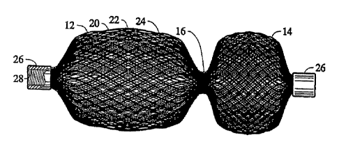
the present invention will next be presented. FIGS. 1-4 illustrate a first
embodiment of a medical
device 10 for treating a vascular abnormality, such as an ASD. The device 10
is shown in FIGS.
1 and 2 in its relaxed, non-stretched state with two aligned disks 12 and 14
linked together by a
short middle cylindrical section 16 (FIG. 3). This device 10 may also be well
suited in occluding
defects such as a PFO. Those skilled in the art will appreciate that a device
of this configuration
may also be suitable for use in a transcatheter closure during a Fenestrated
Fontan's procedure.
The device 10 is sized in proportion to the shunt to be occluded. In the
relaxed
orientation, the fabric is shaped such that two disk like members 12 and 14
are axially aligned
and linked together by the short cylindrical segment 16 (i.e., 4 planes of
occlusion). The length
of the cylindrical segment 16 when not stretched may approximate the thickness
of the atrial
septum and may range, for example, between 3 to 5 mm. The proximal disk 12 and
distal disk 14
may have an outer diameter sufficiently larger than the shunt to prevent
dislodging of the device.
The proximal disk 14 has a relatively flat configuration, whereas the distal
disk 12 may be
cupped towards the proximal end slightly overlapping the proximal disk 14. In
this manner, the
spring action of the device 10 will cause the perimeter edge 18 of the distal
disk to fully engage
the sidewall of the septum and likewise an outer edge of the proximal disk 14
will fully engage
an opposite sidewall of the septum. Perimeter edge 18 of disk 12 as well as
the perimeter edge of
disk 14 may alternatively be configured with a larger radius outer edge
compared to that shown
in FIG. 1, to diminish forces on the tissue abutting the device.
In accordance with one embodiment of the present invention, the device 10
includes an
12
CA 02735528 2011-02-28
WO 2010/030485 PCT/US2009/054476
outer braided layer 20, a first inner layer 22 and an optional third and
innermost layer 24, thereby
significantly increasing the wire density without unduly increasing the
stiffness of the device or
its ability to assume a decreased outer diameter upon longitudinal stretching.
The ends of the
tubular braided metal fabric device 10 may be welded or clamped together with
clamps as at 26,
to avoid fraying. The ends of all of the layers may be grouped together and
secured by two
clamps 26, one at each end or separate clamps can be applied on each end of
the individual
layers. The clamp 26 tying together the wire strands of the multiple layers at
one end may also
serve to connect the device to a delivery system, as described above. In the
embodiment shown
in FIG. 1, the clamp 26 is generally cylindrical in shape and has a recess
(not-shown) for
receiving the ends of the metal fabric to substantially prevent the wires
comprising the woven
fabric from moving relative to one another. The clamp 26 also has a threaded
bore 28. The
threaded bore is adapted to receive and engage a threaded distal end of a
delivery device, such as
a pusher wire.
FIG. 3 illustrates the ASD device 10 in a somewhat longitudinally stretched
state. The
distance separating the distal and proximal disks 12 and 14 is preferably
equal or slightly less
than the length of the cylindrical segment 16. The cup shape of each disk 12
and 14, ensures
complete contact between the outer edge of each disk 12 and 14 and the atrial
septum. Upon
proper placement, a new endocardial layer of endothelial cells may form over
the occlusion
device 10, thereby reducing the chance of bacterial endocarditic and
thromboembolisms.
The distance separating the disks 12 and 14 of occluding device 10 may be
increased to
thereby provide an occluding device suitable for use in occluding a channel
within a patient's
body, having particular advantages in use as a vascular occlusion device. The
relative sizes of the
tubular middle section 16 and the expanded diameter portions 12, 14 can be
varied as desired.
The medical device can be used as a vascular occlusion device to substantially
stop the flow of
blood through a patient's blood vessel. When the device 10 is deployed within
a patient's blood
vessel, it is positioned within the vessel such that its longitudinal axis
generally coincides with
the axis of the vessel segment in which it is being inserted. The dumbbell
shape is intended to
limit the ability of the vascular occlusion device to turn at an angle with
respect to the axis of the
blood vessel to ensure that it remains in substantially the same position in
which the operator
deploys it within the vessel.
In order to position and ensure proper fixation within the lumen of the blood
vessel, the
13
CA 02735528 2011-02-28
WO 2010/030485 PCT/US2009/054476
maximum diameter of the expanded diameter portions 12, 14 should be selected
so that it is at
least as great as the diameter of the lumen of the vessel in which it is to be
deployed and
preferably slightly greater than that diameter. When the device is deployed
within the patient's
vessel, the vascular occlusion device will engage the lumen at two spaced
apart locations. The
device may be longer along its axis than the dimensions of its greatest
diameter. This may
substantially prevent the vascular occlusion device 10 from turning within the
lumen at an angle
to its axis, essentially preventing the device from becoming dislodged and
tumbling along the
vessel within the blood flowing through the vessel.
The relative sizes of the generally tubular middle portion 16 and expanded
diameter.
portions 12, 14 of the vascular occlusion device can be varied as desired for
any particular
application by appropriate selection of a mold to be used during the heat
setting of the device.
For example, the outer diameter of the middle portion 16 may range between
about 1/4 and about
1/3 of the maximum diameter of the expanded diameter portions and the length
of the middle
portion 16 may comprise about 20% to about 50% of the overall length of the
device 10.
Although these dimensions are suitable if the device is to be used solely for
occluding a vascular
vessel, it is to be understood that these dimensions may be varied if the
device is to be used in
other applications, such as a VSD.
The aspect ratio (i.e., the ratio of the length of the device over its maximum
diameter or
width) of the device 10 illustrated in this embodiment is desirably at least
about 1.0, with a range
of about 1.0 to about 3.0 being preferred and then aspect ratio of about 2.0
being particularly
preferred. Having a greater aspect ratio will tend to prevent the device 10
from rotating generally
perpendicularly to its axis, which may be referred to as an end-over-end roll.
So long as the outer
diameter of the expanded diameter portions 12, 14 of the device 10 is large
enough to seat the
device fairly securely against the lumen of the channel in which the device is
deployed, the
inability of the device to turn end-over-end will help keep the device
deployed precisely where it
is positioned within the patient's vascular system or in any other channel in
the patient's body.
Alternatively, having expanded diameter portions 12, 14 which have natural
relaxed diameters
substantially larger than a lumen of the vessels in which the device is
deployed should also
suffice to wedge the device into place in the vessel without undue concern
being placed on the
aspect ratio of the device.
Referring next to FIGS. 5-7, there is shown generally a device 100 suitable
for occluding
14
CA 02735528 2011-02-28
WO 2010/030485 PCT/US2009/054476
a PDA according to one embodiment of the present invention. The PDA device 100
has a
generally bell-shaped body 102 and an outwardly flaring forward end 104. The
bell-shaped body
102 is adapted to be positioned within the aorta to help seat the body of the
device in the shunt.
The base 106 flares out relatively rapidly to define a shoulder 108, tapering
radially outwardly
from the body 102. When the device 100 is deployed in a vessel, this shoulder
108 is configured
to abut the perimeter of the lumen being treated with higher pressure. The
forward end 104 is
retained within the vessel and urges the base of the body 102 open to ensure
that the shoulder
108 engages the wall of the vessel to prevent the device from becoming
dislodged from within
the shunt. The sizes of the body 102 and the end portion 104 can be varied as
desired during
manufacture to accommodate different sized shunts. For example, the body 102
may have a
diameter along its generally slender middle of about 10 mm and a length along
its axis of about
25 mm. In such a medical device 100, the base of the body may flare generally
radially outward
until it reaches an outer diameter equal to that of the forward end 104 which
may be on the order
of about 20 mm in diameter.
With reference to the enlarged view of FIG. 7, the outer layer 110 comprises a
frame that
defines the outer shape of the medical device 100. Within the frame is a layer
112 that forms an
outer liner. There may also be a third layer 114 incorporated as an inner
liner. According to one
embodiment, clamps 120 may be used to tie together the respective ends of the
wire strands on
each end 116 and 118 of the tubular braid members forming the occlusion device
100 as
described above. Alternatively, different clamps may be used to secure the
ends of the metal
strands of the outer fabric layer than are used to secure the ends of the
metal strands of each of
the inner layers. One or both clamps 120 of the outer layer may include a
threaded bore 122 that
serves to connect the device 100 to a delivery system (not shown).
FIGS. 8-10 show various devices according to additional embodiments of the
present
invention, which may be suited for treating a variety of arterial-venous
malformations and
aneurysms. These devices can also be used to block blood flow to a tumor or
lesion. Likewise,
these devices can be used to block fluid flow through a portion of the
vasculature of the body in
connection with the treatment of other medical conditions. Each embodiment
shown in FIGS. 8-
10 may have a multi-layered braided structure 150, i.e., two or more layers of
braided fabric.
When the multi-layered braided structure has a tubular shape, a pair of end
clamps 152 and 154
are provided to prevent the multi-layered braided structure from unraveling.
Those skilled in the
CA 02735528 2011-02-28
WO 2010/030485 PCT/US2009/054476
art will recognize that only a single end clamp is required if the braids are
in the form of a sack
as opposed to having a tubular shape.
The embodiment shown in FIG. 8 has a cylindrical wall 155 with two faces 156
and 158
at the opposite ends (i.e., two planes of occlusion). Generally, when the
device is in its expanded
configuration as shown in FIG. 8, the cylindrical wall abuts the wall of the
vessel in which the
device is deployed to hold the device in place. The two faces 156 and 158
preclude fluid flow
past the device.
In some treatment situations, it may be desirable to increase the number of
faces to
increase the ability of the device to occlude blood flow therethrough. For
example, the device
1o shown in FIG. 9 has a cylindrical wall 155, a proximal face 156, and a
distal face 158. The
embodiment of FIG. 9 further provides an intermediate clamp 160 clamping an
intermediate
portion of the fabric material. This divides the cylindrical wall into two
sections 155a and 155b
and forming two additional faces 162 and 164 (i.e., four planes of occlusion).
When the device of
FIG. 9 is deployed, the two sections 155a and 155b of cylindrical wall 155
still abuts the vessel
wall to hold the device in place yet fluid must to traverse all four faces
(namely faces 156, 158,
162 and 164) to flow past the device. The reduction in flow provided by the
two additional faces
162 and 164 can result in faster clotting. The device shown in FIG. 10 has a
similar
configuration as the device shown in FIG. 9. However, the two sections 155a
and 155b have a
bulbous configuration rather than a cylindrical form. The widest part of
sections 155a and 155b
engage the vessel wall and hold the device in place after deployment.
The intermediate clamp 160 can be made of any suitable material. Suture thread
has
proven to be effective. The two end clamps 152 and 154 are preferably made of
a radiopaque
material so they can easily be visualized using, for example, a fluoroscope.
The intermediate
clamp can be made of such material as well. Also, additional intermediate
clamps can be added
to further increase the number of faces. For example, if two intermediate
clamps are used, a total
of six faces would be present. With each additional clamp, two additional
faces are provided.
Also, when the multi-layered braided structure (or at least one of the layers
thereof) is made of a
superelastic or shape memory material, it may be possible to eliminate the
intermediate clamps
and instead mold the device to have such a shape (e.g., a shape such as that
shown in FIG. 8)
when fully deployed and in its expanded preset configuration.
An alternative embodiment of a device 200 for the treatment of a PDA is shown
is FIGS.
16
CA 02735528 2011-02-28
WO 2010/030485 PCT/US2009/054476
11 a-11 d. The device 200 in its relaxed, unstretched state has two disks 202
and 204 aligned in
spaced relation, linked together by a cylindrical segment 214 (i.e., six
planes of occlusion). The
length of the cylindrical segment 214 may approximate the thickness of the
atrial septum. The
proximal 202 and distal 204 disks may have an outer diameter sufficiently
larger than the cavity,
opening, or the like to prevent dislodgement of the device. The disks 202 and
204 are generally
frustroconical in configuration, with the larger diameter portions facing one
another. Thus, as
shown in FIG. I la, the disks 202 and 204 taper from a smaller diameter C to a
larger diameter B.
The angle F extending between diameters B and C may vary and may be, for
example, between
about 20 and 40 degrees. Similarly, the distance between the smaller and
larger diameter
surfaces of each disk 202 and 204 may vary. The disks 202 and 204 are
configured to extend
inwardly to slightly overlap the cylindrical segment 214, which can be seen in
the cross-sectional
view of FIG. 11 a. As also shown in FIG. 11 a, the cylindrical segment 214
connects with each of
the disks 202 and 204 at a diameter E which is smaller than both the diameter
of the cylindrical
segment and the disks. This configuration may allow the disks 202 and 204 to
easily pivot about
diameters E to allow the disks to align themselves with anatomical vessel
walls that are not
perpendicular to the aperture therebetween. Although the device 200 may have
one or more
layers of occlusive material, FIG. 11 a shows that the device may include an
inner layer 212 and
an outer layer 210. As noted above, the ends 216 and 218 of the braided layers
may be secured
with clamps 220 in order to prevent the braids from unraveling.
FIG. 11 c illustrates a condition where the disks 202, 204 are relatively
parallel but at a
substantial angle to the central section or device axis. The central section
is elongated due to a
smaller passage than anticipated and the elongation accommodates the
lengthened passage
between disks. In FIG. 11 d the disks are non-parallel to accommodate the
walls of the aorta and
again the central section is elongated as it conforms to the passageway
between the disks. FIG.
11 e illustrates a device placed in a para-membranous VSD. In this case the
device is shown
conforming to a thin membrane at the upper portion of the defect and to the
thicker septum in the
bottom portion of the defect. The central section fully expands to shorten the
distance between
disks to aid in clamping force and to fill the defect. FIG. 11 If shows a
device placed in a tear
through a ventricular septum. The device central section 214 elongates to fill
the tear and the
disks conform to the septum walls.
The device 200 is symmetrical so that is may be deliverable by catheter
venously or
17
CA 02735528 2011-02-28
WO 2010/030485 PCT/US2009/054476
arterially, such as from either the pulmonary side or the aortic side as
selected by the physician.
The advantage of a venous approach for PDA closure is to potentially treat
infants as small a 1
kg. The advantage of an arterial approach in slightly larger premature infants
is that both
angiography and device implant can take place from a common access point in
the femoral
artery.
The device 200 may have various dimensions depending on the particular vessel
or
abnormality to be occluded. For example, the cylindrical portion 214 of
diameter C may range
from 2 mm to 6 mm. The length of the cylindrical central section A, may range
from 2 mm to 8
mm. The reduced diameter E may range from 1 mm to 2 mm, preferably 1 mm (or a
tightly
bunched group of wires). The ratio of the large disk diameter B to the small
diameter E may
range from 6 to 12 mm. This ratio may allow the disks to conform or pivot to a
wide range of
wall angles relative to the axis of the PDA, which in the four exemplary
examples of FIG. 11 c-
l If. In addition, the disks may be spaced apart at their outermost point a
distance D that ranges
from 1 mm to 3 mm. The distance between the inner surface of each disk, in the
portion (C)
perpendicular to the device central axis, is G and may range from 3 to 7 mm.
The difference
between distance G and A may provide for passageway length variability and
conformability to
surface irregularities as well as act like a spring to apply clamping pressure
at each disk to the
vessel to hold the device in place. Diameter C may be selected to be slightly
larger (e.g., 10-
20%) than the passageway it is intended for in order to facilitate anchoring
of the device. If the
passageway is longer than anticipated, the central portion can elongate to
accommodate the
longer length.
Other alternative embodiments of the present invention are shown in FIGS. 12a-
12f. In
FIG. 12a the disks 202' and 204' are fabricated from a single layer folded
back on itself, while
the central portion is double layered. FIG. 12f shows an embodiment where the
design is
reversed to have double layers in the disk portion back to back, with a single
layer in the central
portion or a different shape for each layer in the central portion as shown.
FIG. 12b illustrates a
design variation where the multiple braid layers have end wires connected at
one end in a
common clamp 220 but where the inner layer at the opposite end has a clamp 220
that free floats
and is separate from the clamp for the outer layer. In the embodiment of FIG.
12c the inner layer
212 is suspended by suture connectors between the layers and the end clamps of
each layer are
independent of each other. In FIG. 12d the inner layer 212 has independent end
clamps 220 as in
18
CA 02735528 2011-02-28
WO 2010/030485 PCT/US2009/054476
FIG. 12c, but rather than the layers connected by sutures, the layers 210 and
212 have their end
clamps connected by elastic members, such as made from silicone rubber. FIG.
12e is similar to
FIG. 12d except that the connector could be a non-elastomer such as suture or
wire and may be
connected optionally at only one set of end clamps. Like the embodiments of
FIGS. 11 a-11 If, the
embodiments shown in FIGS. 12a-12f have a small transition diameter extending
between each
disk 202' and 204' and the central portion. It is anticipated that the various
optional
characteristics, as shown in FIGS. 12a-12f, could be combined in any manner
desired for any
embodiment described herein.
Various embodiments for treating vascular abnormalities, such as PVLs and
PDAs, are
illustrated in FIGS. 13a-13h. FIG. 13a shows an artificial bi-leaflet valve
sewn by suture 232 into
a patient. Three cross-hatched areas 234, 236, and 238 along the valve cuff
represent open areas
where tissue has pulled away from the cuff from weak tissue or broken or loose
sutures. These
open areas allow blood to short circuit the valve and result in poor heart
function and lower
blood pressure. The shown in FIGS. 13b-13e are configured to close/occlude
these PVLs such as
are shown in FIG. 13a.
With reference to FIG. 13b-I, the outer layer 310 of the device 300 includes a
frame that
defines the outer shape of the medical device 300. Within this frame is an
inner layer 312. The
device 300 may further include a third layer 314 (not shown) as an innermost
liner. As noted
above, the ends 316 and 318 of the braided layers may be secured with clamps
320 in order to
prevent the braids from unraveling.
Since the openings of the vascular abnormalities may be of various shapes it
is
anticipated that a number of sizes and shapes of occluder devices may be
needed to close these
leaks. It is also important that the occluder be positioned securely to
prevent migration or
embolization of the device. As shown in FIG. 13b-I, device 300 is formed of
two layers each
having the same shape. FIG. 13b-II is a plan view of device 300 and FIG. 13b-
III is an end view
thereof. This particular design is intended to occlude openings that are
somewhat oblong in
shape. Radiopaque markers 330 may be placed either on the narrow or wide side
of the expanded
shape to help the physician orient the device as needed. These markers may be
radiopaque
platinum wire or platinum iridium markers attached to the braid in a manner
which does not
impede braid collapse or self expansion. Since the wire diameter is small, the
oblong shape of the
device 300 shown in FIG. 13b may conform to shapes that may be more rounded or
longer. FIG.
19
CA 02735528 2011-02-28
WO 2010/030485 PCT/US2009/054476
13c illustrates a crescent-shaped occluder 324, and FIG. 13d illustrates a
round occluder 326.
The inside radius of the crescent-shaped occluder 324 maybe about 11 , and
the occluder may
incorporate a radiopaque marker to facilitate proper orientation thereof. The
crescent-shaped
occluder 324 may be useful in areas such as around valves. In FIG. 13e, one
edge of the device
that interfaces with the cuff 240 is shaped to match the cuff shape whereas
the other side that
interfaces with the tissue 242 has a shape more conducive to the thickness of
the tissue at the
interface.
Furthermore, FIG. 13g illustrates an additional embodiment of an oblong or
oval-shaped
occluder 300'. In this particular embodiment, the device 300' includes a pair
of oval disks 340,
342 and a portion 344 that is also oval in configuration. Extending between
the disk 340 and the
cylindrical portion 344 is a narrow waist 346 to facilitate articulation
therebetween. At the
opposite side of the device 300', the disk 342 necks down to the oval portion
344. It is
understood that there may also or alternatively be a narrow waist 346
extending between the disk
342 and the oval portion 344 according to additional aspects of the present
invention.
Furthermore, FIG. 13h illustrates that device 300' in an elongated state,
wherein the device may
be elongated for delivery within a delivery device. FIG. 13h also illustrates
that the device 300'
comprises four layers of fabric that are heat set to self expand from an
elongated configuration to
the unconstrained configuration shown in FIG. 13g. Thus, the device shown in
FIG. 13h may
have at least 4 planes of occlusions (i.e., 2 for disk 340 (opposing surfaces
of the disk), 1 for disk
342 (surface opposite the oval portion 344), and 1 for the oval portion 344
(surface coupled to
the waist 346). For illustrative purposes, dimensions are given for the oblong
occluders of FIGS.
13b and 13g in Tables 1 and 2, as well as dimensions for exemplary delivery
catheters for
delivering such devices. As shown in Table 2, the oblong occluders may have
two to four layers
of occlusive fabric material. The dimensions of each Braid Layer in Table 2
correspond to the
strand diameter, number of strands, and the diameter of the mandrel on which
the strands were
braided.
Table 1
Waist Device Sheath Minimum Guide C (mm) D (mm) I (mm) G (mm
(E X B mm) Length Minimum ID (in.) Catheter
(F mm) Minimum
4x2 6.5 5F 0.066 6F 8.0 6.0 21.0 4.0
CA 02735528 2011-02-28
WO 2010/030485 PCT/US2009/054476
6x3 6.5 5F 0.066 6F 10.0 7.0 25.25 4.0
8x4 6.5 5F 0.074 7F 12.0 8.0 29.5 4.0
10x5 6.5 6F 0.070 8F 14.0 9.0 33.0 4.0
12x5 6.5 6F 0.070 8F 16.0 9.0 36.5 4.0
14x5 6.5 7F 0.070 9F 18.0 9.0 44.0 4.0
Table 2
Device Size (mm) Braid Layer A Braid Layer B Braid Layer C Braid Layer D
4 x 2 0.0015x144x8 mm 0.0015x144x8 mm N/A N/A
6 x 3 0.0015x144x12 mm 0.0015x144x12 mm 0.0015x144x12 mm N/A
8x4 0.0015x144x12 mm 0.0015x144x12 mm 0.002x144x12 mm N/A
10x5 0.0015x144x15 mm 0.0015x144x15 mm 0.002x144x15 mm N/A
12 x 5 0.0015x144x17 mm 0.0015x144x17 mm 0.002x144x17 mm 0.002x144x17 mm
14 x 5 0.0015x144x20 mm 0.0015x144x20 mm 0.002x144x20 mm 0.002x144x20 mm
FIG. 13f illustrates an exemplary clamp 320 for the device 300 intended to be
compatible
with delivery of the occluder over a guidewire. In this design the clamps 320
have a central
passage 338 for the guidewire to slidable pass there through. The clamp 320 is
therefore
fabricated with an inner ring 330 having an inside diameter slightly larger
(e.g., about 0.002-
0.004 inch) larger than the guidewire diameter. The clamp also has an outer
ring 332 large
enough to contain the braided wire ends between the two rings. The outer ring
332 may be
swaged to compress the outer ring against the wires and the inner ring 330 or
the wire ends and
rings may be welded, brazed, soldered or held by adhesive or other known
techniques. At least
one of the clamps may have threads either externally on the outer ring of the
clamp or internally
in the inner ring to accommodate a threaded delivery device having an internal
lumen sized for
passage of a guide wire therethrough.
Another embodiment of an occluder is a variation of the devices shown in FIGS.
12a-12f,
whereby the occluder device 400, as shown in FIGS. 14a-14c, includes a soft,
conformable, outer
braid 410 enclosing a volume 430 that is pre-shaped as desired, with two or
more internal
braided tubular members 412a, 412b, 412c side by side with shared braid end
wire connectors
420 at least at one end. As can be seen in FIGS. 14b and 14c, the multiple
braids need not be
concentric. This arrangement allows the inner braided members 412 to shift
relative to one
another to fill the available volume of unknown size or shape such as an
oblong, crescent, or oval
cavity shape. This is accomplished by selecting a heat set shape for braids
412 that have a large
enough diameter to exert a force against the outer tubular braid 410 to compel
the outer braid
against the wall of the cavity the device is placed in. To share a common end
wire clamp 420 the
21
CA 02735528 2011-02-28
WO 2010/030485 PCT/US2009/054476
internal braided members 412 may be clamped with end clamps 420, such as by
compressing the
braided members against each other at the ends and shaped into a crescent to
fit in annular
fashion about the end clamp 420. The proximal clamp 420 at wire end 418 may
have threads (not
shown) for connection to a delivery catheter (not shown). The proximal wire
ends of braids 412
be connected to clamp 420 by means of a tether or elastic member to allow for
a braid length
change that would vary based on the shape of the device 400 within a cavity.
In addition, an
optional over the guidewire delivery embodiment may be employed as described
in previous
embodiments.
In a further embodiment of a device 500 shown in FIG. 15, the outer braid 510
may be
pre-shaped to define a volume shape 530 that is soft and conformable.
Contained within the outer
braid and coaxially sharing the outer braid distal wire end clamp 520 is a
smaller diameter
tubular braid 512 that is pre-shaped into a bead and chain shape. The internal
smaller braid 512 is
much longer than the outer braid 510 and is designed to meander into the outer
braid defined
volume 530 as braid 512 is inserted to fill the volume completely and help the
outer braid to
conform to the cavity shape it is within. The distal braided wire end clamp
520 at wire end 516 is
preferably a two part clamp arrangement with an internal ring and external
ring pinching the
braid wires between the rings. The proximal braided wire end clamp 522 is
similarly constructed
but the outer ring is threaded to mate with threads on the delivery catheter
540 for selective
connection between the device and the delivery catheter. In this embodiment, a
portion of the
inner braid remains within the delivery catheter when the outer braid is fully
deployed. In order
to deliver the balance of the inner tubular braid 512 into the volume 530, a
pusher wire 528
within the delivery catheter 540 acts against the proximal end wire end clamp
523 of braid 512 to
advance the braid completely out of the delivery catheter. The pusher wire 528
may optionally
have a threaded end to engage with optional threads in the wire end clamp 523.
The delivery
catheter 540 may be advanced to the treatment site through a sheath. The high
density of wire
within the volume 530 may facilitate rapid hemostasis while maintaining a low
profile for
delivery. The spherical shape of the bead chain fills the volume with sphere
against sphere
against the outer braid and thereby loads the outer braid surface against the
cavity wall desired to
be occluded. The wire end clamps 520 and 523 may be of the two ring
configuration as
previously described in other embodiments to allow the device to be configured
for over the
guidewire delivery.
22
CA 02735528 2011-02-28
WO 2010/030485 PCT/US2009/054476
In another embodiment as shown in FIGS. 16a-16d, intended primarily for para-
membranous VSD occlusion. The device may have one articulating flange 600
(right chamber)
with a small transition diameter E, and the flange 602 on the opposing end
(left chamber) may be
smaller in diameter to prevent interference with the aortic valve. The single
articulating flange
600 may reduce pressure of the conductive His bundle to help prevent heart
block, and the lack
of articulation on the left chamber side may better resist dislodgement of the
device from the
higher arterial blood pressure (FIGS. 16b and 16c). In order to relieve the
left chamber flange
602 diameter to prevent interference with the aortic valve, the left chamber
flange may be offset
from the central axis with respect to the central device portion so that the
flange is displaced
away from the valve as shown in FIG. 16d. Further modification, by eliminating
transition
diameter E is also anticipated as shown in FIG. 16d.
As described above, medical devices according to embodiments of the present
invention
may include a layer that comprises at least portion of polymeric material. The
polymeric
material can include, for example, polyester (e.g., polyethylene
terephthalate, expanded
polytetrafluoroethylene, polycaprolactone, poly(glycolic acid), or
polylactide), polyolefin (e.g.,
polypropylene), polyamide (e.g., nylon 6 or nylon 6, 6), polysulphonate,
polycarbonate, and/or
polyurethane. The polymeric material may be a braided fabric of polymeric
strands, such as with
single filaments or multi-filaments, and the fabric layer may include one or
more polymeric
materials.
As briefly mentioned above, the medical device may include a fabric layer of
braided
strands of polymeric material, or the fabric layer may be a combination of
braided stands of
metallic and polymeric material (i.e., a composite material). The strands may
be braided with
alternating strands of polymeric and metallic materials in opposite or both
helix directions to
form a composite, single braided structure. For example, FIG. 20 shows that a
braided fabric
900 may include strands of metallic material 902 and polymeric material 904
braided in both
helix directions. Alternatively, or additionally, the strands of metallic
material may be twisted
with the strands of polymeric material, such that the braided fabric is a
composite material of
metallic/polymeric strands. The metallic strands may not be used &s structural
support but,
rather, to flatten the polymeric strands and improve the coverage and handling
of the fabric layer.
For instance, polymeric strands having a substantially circular cross section
may be flattened to a
substantially rectangular cross section when braided with metallic strands
thereby decreasing the
23
CA 02735528 2011-02-28
WO 2010/030485 PCT/US2009/054476
pore size between the braided strands. The metallic material may be a shape-
memory material as
described above or may be formed of strands of a material that do not have
shape memory
properties. In a multi-layered medical device, one layer may be a metallic
material that may or
may not be the same as the metallic material of a composite layer of metallic
and polymeric
materials.
The layer of polymeric material may be configured to be heat set to the
expanded shape.
For example, in one embodiment, the polymeric material is a heat-settable
polymer, wherein the
polymer may be shaped by application of heat to a softening point, formed into
a desired shape,
and then cooled to retain the shape. Examples of heat-settable polymers
include, but are not
limited to, polyesters, polypropylenes, polyethylenes, or polyurethanes. In
some embodiments,
the heat-settable polymer may be a polymeric shape memory material. Examples
of shape
memory polymers include, but are not limited to, oligo(e-caprolactone)
dimethacrylate n-butyl
acrylate. Where the layer comprises a composite of polymeric and metallic
materials, the
metallic material may be heat set at a lower temperature that is compatible
with the polymeric
material.
According to one embodiment, the metallic/composite layer is not heat set, but
is rather
coated with an elastomeric material to hold the shape by elastically linking
cross-over points of
the filaments while still being configured to be constrainable to a reduced
shape through the
application of external force and to subsequently assume an expanded shape
when the external
force is removed, as described above. For instance, the elastomeric coating
may be a silicone or
urethane material. Thus, the composite layer can be composed at least
partially of strands of a
metallic material that do not have shape memory properties, such as stainless
steel.
The layer including at least a portion of polymeric material may be disposed
either within
or around the layer of metallic material. For example, the layers may be
disposed in an
overlying relationship with one another, such that one layer is disposed
radially within the other,
such as outer and inner layers shown in FIGS. 1 la and 13b. In addition, the
layers may be
disposed either generally concentrically relative to one another or such that
the central axes of
the layers are not aligned with one another. For instance, the inner and outer
layers could be
tubular and substantially similar in shape and have a common central axis. The
extent to which
the expanded shapes of the layers are mutually similar will affect how
completely the layers nest
with one another, and the layers may have at least partially similar expanded
shapes in order to
24
CA 02735528 2011-02-28
WO 2010/030485 PCT/US2009/054476
facilitate nesting therebetween. However, it is understood that the layers may
have dissimilar
expanded or undeformed shapes. For example, FIG. 17 illustrates a medical
device 700 that may
include an inner layer 704 that is constructed of a material(s), such as a
layer made solely of
polymeric material, that is sufficiently compliant in order to allow the inner
layer to generally
conform to the shape of the outer layer 702 in an expanded shape.
In some cases, the nesting of the layers within one another may suffice to
couple the
layers together, while in other cases a fastener or other techniques may be
used to couple the
layers together. The fastener may include, for example, end clamps configured
to
simultaneously secure free ends of respective strands of the layers.
Alternatively, or
additionally, the fastener may include sutures that couple the layers at one
or more points along
their length, or an elastic adhesive, such as epoxy, that is applied at one or
more points between
the two layers. The suture may comprise radiopaque material such as platinum
ribbon, which
may be used to orient or otherwise position the medical device within a lumen
for treating a
target site. As another alternative, each of the layers may be respectively
associated with distinct
first and second end clamps, and the first and second end clamps can be
connected to one
another.
As also indicated above, the multi-layered medical device may be configured to
be
cooperatively constrainable to a common reduced shape through the application
of external force
and to subsequently cooperatively assume a common expanded shape when the
external force is
removed. For example, first and second layers may be respectively braided at
approximately the
same braid pitch so as to retain substantially similar length-to-diameter
ratios when axially
elongated. In this way, when the layers are disposed one within the other,
simultaneous axial
elongation of both of the layers may result in the layers together moving into
mutually similar
reduced shapes. Such simultaneous elongation may be initiated, for example, by
applying force
to one layer, which then urges the other tube into a similar shape due to the
two layers being
coupled together.
In order to facilitate the transition between the expanded and reduced shapes,
the layers
may have different physical properties. For example, a second layer of
material may be
configured so as to be more compliant than a first layer of material, and the
second layer may be
disposed within the first layer. For example, where the second layer includes
strands of metallic
and polymeric material, the metallic strands of the second layer may have
diameters smaller than
CA 02735528 2011-02-28
WO 2010/030485 PCT/US2009/054476
the diameters of the strands of metallic material of the first layer. For
example, the first layer
may have a metallic strand diameter of about 0.004 inches, while the second
layer may have a
metallic strand diameter of about 0.002 inches. This may allow the first layer
to dictate the
overall configuration of the medical device when the first layer is subject to
deformation by an
external force. Moreover, the first layer may have about 36-144 strands and a
braided diameter
of about 3-45 mm, a pick count of about 20-150 picks/inch, and a fenestration
size of about
0.00015-0.05 square inches. The second layer may have about 72 metallic
strands and 72
polymeric strands of a multi-filament strand of about 100-400 denier. However,
it is understood
that the particular configuration of the first and second layers may vary
depending on the type of
medical device and particular physical properties desired.
As also indicated above, medical devices according to various embodiments of
the
present invention may comprise three layers of material, such as shown in
FIGS. 2 and 7. For
instance, a medical device may comprise a second layer including at least a
portion of polymeric
material sandwiched between first and third layers of metallic material.
According to one
embodiment, the second layer can be disposed radially within the first layer,
and the second layer
can be disposed radially within the third layer such that the second layer is
located between the
first and third layers. In other embodiments, the second layer may be disposed
radially within
the first layer, or the third layer may be radially disposed within the second
layer.
The first layer may be configured to outwardly compress the second layer
against the
third layer. The compression of the second layer between the first and third
layers may cause the
second layer to generally conform to the profiles of the first and third
layers, and may act to
secure the second braided tube in place between the first and third layers,
and as such, separate
fasteners may not be required in order to secure the second layer in position.
End clamps may be
employed to clamp the free ends of one or more of the strands of the layers
together, such as by
clamping the ends of all of the layers or only clamping the ends of the first
and third layers
together.
The third layer may be configured to be constrainable to a reduced shape
through the
application of external force and to subsequently assume, when the external
force is removed, an
expanded shape. The expanded shape of the third layer may have at least a
portion that is similar
to the expanded shape of the first layer, which may facilitate mating or
nesting of at least a
portion of the first and third braided tubes and compression of the second
layer therebetween.
26
CA 02735528 2011-02-28
WO 2010/030485 PCT/US2009/054476
The second layer may or may not have an expanded/undeformed shape that is
similar to that of
the first or third layers.
The third layer may be configured to be more compliant than the first layer.
For
example, the third layer can have a density of metallic strands that is less
than a density of the
metallic strands of the first layer. In some embodiments, the strands of
metallic material of the
third layer may have smaller diameters than those of the strands of metallic
material of the first
layer since the third layer may be predominantly employed to retain the second
layer in position,
and the first layer may be employed to provide structural support. The first
layer may for
example have 72 braided metal strands of 0.003 to 0.006 inch diameter where as
the third layer
may have 144 braided metal strands of 0.0015 to 0.003 inch diameter. The third
layer may
alternatively have an increased number of strands in comparison to the first
layer in order to
increase its density and occlusive properties. Moreover, the strand diameter
of the first layer in a
three-layer device may have a reduced diameter in comparison to the strand
diameter of a two-
layer device, since the third layer also adds structural support. Furthermore,
in order to facilitate
the placement of the layers in an overlying relationship with one another, the
layers can be
braided over respective mandrels of approximately the same or different
diameters, which may
produce layers that can accommodate one another. For example, the third layer
could be braided
over a mandrel having a diameter that is approximately 1 mm larger than a
diameter of the
mandrel that the second layer is braided upon.
FIGS. 18 and 19 illustrate a medical device according to another embodiment of
the
present invention. The medical device 800 could be, for example, a stent
graft. The medical
device includes a structure, such as a braided tube 802, that has braided
strands 806 of metallic
material and defines a longitudinal axis A. The braided tube 802 can be
configured to be
constrainable to a reduced shape through the application of external force and
to subsequently
assume an expanded shape when the external force is removed.
As alluded to previously, at least one layer of material may be formed by
wrapping a
strand of polymeric material about at least one underlying layer. For
instance, FIG. 18 shows a
strand 808 of polymeric material disposed spirally around the outer surface of
the braided
tube 802 (note that FIG. 18 only shows the strand wrapped partially along the
length of the inner
layer). For example, the polymeric strand 808 may be continuously in contact
with a radially
exterior surface 803 of the braided tube 802, spiraling around the
longitudinal axis A. In some
27
CA 02735528 2011-02-28
WO 2010/030485 PCT/US2009/054476
embodiments, the strand 808 may be configured to facilitate thrombosis.
According to another
embodiment, a second strand (or the same strand) may be spirally wrapped in an
opposite
direction to form a layer on top of the first layer formed by the first strand
808. Thus, the
medical device 800 may include any number of layers of spirally wrapped
strands 808. The
strand 808 may be secured in position using different techniques, such as by
tying or gluing the
ends of the strand to a wire at each end. The strand 808 may be adhered or
sutured to the wire
braid at select locations along the length of the medical device 800.
The braided strands 806 of the braided tube 802 can be configured to have a
braid
pitch P1 and a diameter D1, as shown in FIG. 19. The polymeric strand 808 can
be disposed
helically around the braided tube at a pitch P2 and an inner diameter D2, with
the longitudinal
axis A generally serving as the axis of the helical curve of the strand. FIG.
19A shows an
exemplary strand 808 that is wrapped in a helical configuration. In some
embodiments, when
the diameter DI is approximately equal to the diameter D2 (e.g., when the
polymeric strand 808
is in contact with the outer surface 803 of the braided tube 802), the pitch
P1 may be
approximately the same as the pitch P2. When the medical device 800 is axially
elongated, for
example, by an elongation force, the strand 808 may remain in generally
continuous contact with
the outer surface 803, such that the internal diameter formed by the spiral
strand remains
approximately the same as the external diameter of the elongated tube 802.
Moreover, the denier and/or density of the polymeric strands 808 in each layer
may be
the same or substantially similar to the denier and density of the underlying
braided fabric layer.
Alternatively, the denier and/or density of the polymeric strands 808 may be
greater than the
inner layer, which may improve the occlusive properties of the medical device
800. For
instance, the strands 808 may comprise a smaller diameter in order to provide
a greater density
and more flexibility. According to one embodiment, the medical device 800 may
include a third
or outer layer of material disposed over the spirally wrapped strand 808. For
example, the outer
layer may comprise a braided fabric of metallic strands. Thus, either the
outer or inner layers
may be sufficient to provide structural support for the spirally wrapped
strand 808 that is
disposed therebetween.
The embodiments described above may be employed for treating various vascular
abnormalities, such as PDA, VSD, ASD, PFO, PVL, or any other similar
abnormality. The
various occluder embodiments described above may occlude relatively quickly
compared to
28
CA 02735528 2011-02-28
WO 2010/030485 PCT/US2009/054476
prior art devices due the increased number of occlusion planes, as well as the
small pore size and
large surface area created by the multitude of wires resulting from using
multiple layers of
occlusive material. Because of the increase in the number of wire strands in a
composite multi-
layer structure, it may no longer be necessary to incorporate a sewn-in
polyester material in order
to reduce the time required to establish total occlusion of a PDA, VSD, ASD,
PFO, PVL, or
other vascular location. In addition, the occluder devices may have a lower
profile, improved
retention force, and improved conformability to adjust to a variety of vessel
passageways with
minimal interference in the native vessel flow. The reduced profile of this
device may be
configured for delivery within a 4 French catheter or sheath. Over the
guidewire tracking offers
options for delivery to difficult to reach anatomy. Due to device symmetry,
some embodiments
are deliverable from either the venous or arterial side of the same defect.
Many modifications and other embodiments of the inventions set forth herein
will come
to mind to one skilled in the art to which these inventions pertain having the
benefit of the
teachings presented in the foregoing descriptions and the associated drawings.
Therefore, it is to
be understood that the inventions are not to be limited to the specific
embodiments disclosed and
that modifications and other embodiments are intended to be included within
the scope of the
appended claims. Although specific terms are employed herein, they are used in
a generic and
descriptive sense only and not for purposes of limitation.
29