Note: Descriptions are shown in the official language in which they were submitted.
CA 02735546 2016-05-24
IMAGING BASED ON COSMIC-RAY PRODUCED CHARGED PARTICLES
Background
[0002] This patent document relates to detection of cosmic radiation and
imaging based on
imaging based on cosmic-ray produced charged particles.
[0003] Cosmic ray tomography is a technique which exploits the multiple
Coulomb scattering
of cosmic ray-produced charged particles (e.g., muons) to perform non-
destructive inspection of
the material without the use of artificial radiation. The earth is
continuously bombarded by
energetic stable particles, mostly protons, coming from deep space. These
particles interact with
atoms in the upper atmosphere to produce showers of particles that include
many short-lived
pions which decay producing longer-lived muons. Muons interact with matter
primarily through
the Coulomb force having no nuclear interaction and radiating much less
readily than electrons.
Such cosmic ray-produced particles slowly lose energy through electromagnetic
interactions.
Consequently, many of the cosmic ray-produced muons arrive at the earth's
surface as highly
penetrating charged radiation. The muon flux at sea level is about 1 muon per
cm2 per minute.
Also at sea level, there exists a flux of cosmic ray generated electrons, from
delta ray production
(electron knock-out), Bremsstrahlung or the decay of particles in cosmic ray
induced showers.
The electron flux at sea level is about 1 electron per cm2 per 3 minutes.
[0004] As a charged particle such as a muon moves through material, Coulomb
scattering off of
the charges of sub-atomic particles perturb its trajectory. The total
deflection depends on several
material properties, but the dominant effect is the atomic number, Z, of
nuclei. The trajectories of
charged particles (e.g., muons) are more strongly affected by materials that
make good gamma
ray shielding, such as lead and tungsten, and by special nuclear materials
1
CA 02735546 2011-02-28
WO 2010/025300 PCT/US2009/055253
(SNMs), such as uranium and plutonium, than by materials that make up more
ordinary
objects such as water, plastic, aluminum and steel. Each charged particle
(e.g., a muon)
carries information about the objects that it has penetrated. The scattering
of multiple
charged particles (e.g., muons) can be measured and processed to probe the
properties of
these objects. A material with a high atomic number Z and a high density can
be detected
and identified when the material is located, inside low-Z and medium-Z matter.
[0005] Coulomb scattering from atomic nuclei in a matter results in a
very large number
of small angle deflections of charged particles as the transit the matter. A
correlated
distribution function can be used to approximately characterize the
displacement and angle
change of the trajectory that depends on the density and the atomic charge of
the material. As
an example, this distribution function can be approximated as a Gaussian
distribution. The
width of the distribution function is proportional to the inverse of the
momentum of the
particle and the square root of the real density of material measured in
radiation lengths. The
correlated distribution function of cosmic ray-produced charged particles
(e.g., muons) can
provide information on materials in the paths of the charged particles with no
radiation dose
above the earth's background and proper detection of such cosmic ray-produced
charged
particles (e.g., muons) can be implemented in a way that is especially
sensitive to selected
materials to be detected such as good radiation shielding materials.
[0006] A charged particle tomography detection system, e.g., a muon
tomography
detection system, can be configured to perform tomography of a target object
under
inspection based on scattering of charged particles by the target object and
can be used as a
portal monitor at various locations, such as border crossing points, ports,
roadway
checkpoints and other security checkpoints, for detecting certain targeted
objects such as
smuggled nuclear materials, nuclear and conventional weapons or other
contraband. Charged
particle tomography detector systems can be used jointly with or an
alternative to other
nuclear material detectors such as gamma or X ray detectors. Gamma and X ray
detectors
operate by directing Gamma and X ray radiation to a target and measuring
penetrated Gamma
and X ray radiation. Shielding of nuclear materials can reduce the count rates
in the Gamma
and X ray detectors and reduce the detection performance of Gamma and X ray
detectors.
Charged particle tomography detection systems can be configured to detect
shielded nuclear
materials and objects.
2
CA 02735546 2011-02-28
WO 2010/025300 PCT/US2009/055253
Summary
[0007] This document provides techniques, apparatus and systems for
obtaining
tomographic images of a volume of interest by using charged particle
tomography detection
systems.
[0008] In one aspect, a method for sensing a volume exposed to charged
particles
includes measuring energy loss of charged particles that enter and penetrate
the volume or are
stopped inside the volume without penetrating through the volume; based on the
measured
energy loss, determining a spatial distribution of the charged particles that
enter and penetrate
the volume or are stopped inside the volume without penetrating through the
volume; and
using the spatial distribution of the energy loss of the charged particles to
reconstruct the
three-dimensional distribution of materials in the inspection volume.
[0009] In another aspect, a tomography inspection system is provided to
include a first set
of position sensitive detectors located on a first side of an object holding
area to measure
positions and directions of incident charged particles entering the object
holding area; a
second set of position sensitive detectors located on a second side of the
object holding area
opposite to the first side to measure positions and directions of outgoing
charged particles
exiting the object holding area, or the absence of charged particles that have
stopped in the
volume; and a signal processing unit to receive data of measured signals of
the incoming
charged particles from the first set of position sensitive detectors and
measured signals of the
outgoing charged particles from the second set of position sensitive
detectors. The signal
processing unit is configured to analyze behaviors of the charged particles
caused by
interactions with materials within the object holding area based on the
measured incoming
and outgoing positions and directions of charged particles to obtain a
tomographic profile or
the spatial distribution of materials within the object holding area. The
signal processing unit
is operable to measure energy loss of charged particles that enter the volume
and penetrate
through the volume, and charged particles that are stopped inside the volume
without
penetrating through the volume, determine a spatial distribution of the
charged particles that
enter the volume and penetrate through the volume and charged particles that
are stopped
inside the volume without penetrating through the volume; and, based on the
measured
energy loss, using the spatial distribution to reconstruct the spatial
distribution of materials
within the inspection volume.
3
CA 02735546 2016-05-24
object holding area without penetrating through the object holding area. Based
on the measured
energy loss, the signal processing unit uses the spatial distribution of the
charged particles that
enter the object holding area and penetrate through the object holding area
and charged particles
that are stopped inside the object holding area to reconstruct the spatial
distribution of materials
within the object holding area.
[0009] In accordance with another embodiment, there is provided a method
for sensing a
volume exposed to charged particles. The method involves using a first set of
position sensitive
detectors located on a first side of the volume to measure positions and
directions of incident
charged particles that penetrate the first set of position sensitive detectors
to enter the volume.
The method further involves using a second set of position sensitive detectors
located on a
second side of the volume opposite to the first side to measure positions and
directions of
outgoing charged particles exiting the volume or the lack thereof, and using
measurements made
by the second set of position sensitive detectors to determine incident
charged particles that enter
the volume and penetrate through the volume and charged particles that do not
penetrate through
the volume to reach the second set of position sensitive detectors. The method
further involves
determining energy loss of charged particles that enter the volume and
penetrate through the
volume and charged particles that are stopped inside the volume without
penetrating through the
volume and determining a spatial distribution of the charged particles that
enter the volume and
are stopped inside the volume without penetrating through the volume, based on
measured
energy loss. The method further involves using the spatial distribution of
charged particles that
enter the volume and are stopped inside to reconstruct the spatial
distribution of materials in the
volume.
[0010] In another embodiment, there is provided a method for sensing a
volume exposed to
charged particles. The method involves measuring energy loss of charged
particles that enter the
volume and are stopped inside the volume without penetrating through the
volume, based on the
measured energy loss, determining a spatial distribution of the charged
particles that enter the
volume and are stopped inside the volume without penetrating through the
volume, and using the
spatial distribution to detect presence of one or more low density materials
with low atomic
numbers.
4
CA 02735546 2016-05-24
100111 The method may involve measuring the charged particles that enter
and penetrate
through the volume to determine presence of one or more high density materials
with atomic
numbers higher than the low atomic numbers of one or more low density
materials, and
combining measurements of both the one or more high density materials and the
one or more low
density materials to inspect content inside the volume.
[0012] In another embodiment, there is provided a tomography inspection
system. The
system includes a first set of position sensitive detectors located on a first
side of an object
holding area to measure positions and directions of incident charged particles
towards the object
holding area, and a second set of position sensitive detectors located on a
second side of the
object holding area opposite to the first side to measure positions and
directions of outgoing
charged particles exiting the object holding area. The system further includes
a signal processing
unit to receive data of measured signals of the incoming charged particles
from the first set of
position sensitive detectors and measured signals of the outgoing charged
particles from the
second set of position sensitive detectors. The signal processing unit is
configured to analyze
scattering behaviors of the charged particles caused by scattering of the
charged particles in
materials within the object holding area based on the measured incoming and
outgoing positions
and directions of charged particles to obtain a tomographic profile or a
spatial distribution of
scattering centers within the object holding area. The signal processing unit
is operable to
measure energy loss of charged particles that enter the object holding area
and are stopped inside
the object holding area without penetrating through the object holding area,
and is operable to
determine a spatial distribution of the charged particles that enter the
object holding area and are
stopped inside the object holding area without penetrating through the object
holding area, and
based on the measured energy loss, use the spatial distribution to detect
presence of one or more
low density materials with low atomic numbers.
[0013] In another embodiment, there is provided a method for sensing a
volume exposed to
charged particles. The method involves using a first set of position sensitive
detectors located on
a first side of the volume to measure positions and directions of incident
charged particles that
penetrate the first set of position sensitive detectors to enter the volume,
and using a second set
CA 02735546 2016-05-24
of position sensitive detectors located on a second side of the volume
opposite to the first side to
measure positions and directions of outgoing charged particles exiting the
volume. The method
further involves using measurements made by the second set of position
sensitive detectors to
determine incident charged particles that enter the volume and do not
penetrate through the
volume to reach the second set of position sensitive detectors, and
determining energy loss of
charged particles that enter the volume and are stopped inside the volume
without penetrating
through the volume. The method further involves determining a spatial
distribution of the
charged particles that enter the volume and are stopped inside the volume
without penetrating
through the volume, based on the measured energy loss and using the spatial
distribution to
detect presence of one or more low density materials with low atomic numbers
inside the
volume.
[0014] The method may involve measuring the charged particles that enter
and penetrate
through the volume to determine presence of one or more high density materials
with atomic
numbers higher than the low atomic numbers of one or more low density
materials, and
combining measurements of both the one or more high density materials and the
one or more low
density materials to inspect content inside the volume.
[0015] The method may involve using comic ray produced muons that naturally
exist on the
earth surface as a source of the charged particles without using an artificial
radiation source to
generate the charged particles in sensing the volume.
[0016] The method may involve using measurements of energy loss of only the
charged
particles that enter and penetrate the volume, without using measurements of
the energy loss of
the charged particles that are stopped inside the volume without penetrating
through the volume,
to reconstruct the spatial distribution of one or more materials in the
volume.
[0017] The method may involve using measurements of energy loss of only the
charged
particles that are stopped inside the volume without penetrating through the
volume, without
using measurements of the energy loss of the charged particles that enter and
penetrate the
volume, to reconstruct the spatial distribution of one or more materials in
the volume.
6
CA 02735546 2016-05-24
[0017a] The method may involve using measurements of energy loss of electrons
that are
produced by the comic ray produced muons inside the volume and that are
stopped inside the
volume without penetrating through the volume, to reconstruct the spatial
distribution of one or
more materials in the volume.
[0017b] The method may involve using measurements of energy loss of positrons
that are
produced by the comic ray produced muons inside the volume and that are
stopped inside the
volume without penetrating through the volume, to reconstruct the spatial
distribution of one or
more materials in the volume.
[0017c] The system may use comic ray produced muons that naturally exist on
the earth's
surface as a source of the incident charged particles to the object holding
area without using an
artificial radiation source.
[0017d] The method may involve using comic ray produced muons that naturally
exist on the
earth's surface as a source of the charged particles without using an
artificial radiation source to
generate the charged particles in sensing the volume.
[0017e] The method may involve using comic ray produced muons that naturally
exist on the
earth's surface as a source of the charged particles without using an
artificial radiation source to
generate the charged particles in sensing the volume.
[0017f] The system may use comic ray produced muons that naturally exist on
the earth's
surface as a source of the incident charged particles to the object holding
area without using an
artificial radiation source.
[00018] These and other aspects are described in greater detail in the
drawings, the description
and the claims.
Brief Description of Drawings
[00019] FIG. 1 illustrates operations of an exemplary draft tube gas chamber
for detecting
charged particles.
7
CA 02735546 2016-05-24
[00020] FIG. 2 shows an example of a muon tomography system based on gas
chambers
described in this application.
[00021] FIG. 3 an estimate of the sea level cosmic ray flux broken into its
electron and muon
components.
[00022] FIG. 4 shows an illustration of the two modes of using cosmic rays
discussed in this
paper. On the left (a) is an illustration of a transmitted cosmic ray and on
the right (b) is an
illustration of a stopped cosmic ray.
[00023] FIG. 5 shows an effective mean free path as a function of energy. This
estimate has
ignored electron showering, and has assumed an energy loss of 2 MeV/g/cm2.
[00024] FIG. 6 shows a plot of the stopping power and radiation lengths for a
set of normal
materials and explosive materials along with the measurement error bars
expected for a
22x22x22cm3 sized simple of these materials in a one minute exposure.
[00025] FIG. 7 shows the product of the minimum value of the energy loss
(dE/dx) and
radiation length is plotted across the periodic table.
[00026] FIG. 8 shows a plot of the 2 dimensional distribution of stopped
cosmic ray particles
in a 20 kg block of Tungsten. The red peak represents the additional stopped
7a
CA 02735546 2011-02-28
WO 2010/025300 PCT/US2009/055253
particles in the tungsten block and is located at the X-Y position of the
tungsten in the
detector.
[00027] FIG. 9 shows an example of the stopping power for charged particles
versus
charged particle incident energy.
[00028] FIG. 10 shows an example illustration of the energy loss measurement
in
materials and how the measured loss probes properties of the materials in the
volume of
interest.
[00029] FIG. 11 shows an operation of the system in FIG. 2 based on
information
measured in both penetrated charged particles and trapped charged particles.
Detailed Description
[00030] The charged particle tomography detection techniques, apparatus and
systems
described in this application can be implemented to detect the presence of
certain objects or
materials such as nuclear materials and to obtain tomographic information of
such objects in
various applications including but not limited to inspecting packages,
containers, occupied
vehicles at security check points, border crossings and other locations for
nuclear threat
objects that may range from fully assembled nuclear weapons to small
quantities of highly
shielded nuclear materials. The approach enables detection of shielded and
unshielded
nuclear material using a single detector system in a compact configuration to
provide a cost
effective way for detecting nuclear and other targeted devices and materials.
[00031] Background cosmic radiation provides a source that can be used to
study the
internal structure of objects with no need for additional radiation. Muon
tomography (MT)
produces 3-dimensional images of the "scattering density," the density
weighted by the
radiation length of a material. MT can discriminate between general classes of
materials
(high-, medium-, low-Z) in sub-one minute exposure times in 5 cm voxels. Range
radiography, which uses the component of the cosmic ray flux that stops in an
object being
studied, provides added information and can complement the muon tomography
signal in a
way that provides information about the material composition of objects. A
cosmic ray
tracker, which measures the incident particles, adds considerable statistical
power to the
range information.
8
CA 02735546 2011-02-28
WO 2010/025300 PCT/US2009/055253
[00032] Charged particle tomography takes advantage of the constant sea-level
flux of
charged particles generated via interactions of cosmic radiation with the
Earth's atmosphere.
Outside the hadronic sector, the muon interacts only via the Coulomb and weak
forces, for
example. Because of this, it is highly penetrating of matter. These charged
particles have an
average energy of approximately 3 GeV. For example, most atmospheric muons
will
penetrate more than a meter of lead. Muons reach the surface with a cosine-
squared
distribution in zenith. Flux is low at angles off zenith close to 90o, but the
average muon
angle off zenith is 37.5 .
[00033] Features described in this application can be used to construct
various charged
particle tomography detection systems. For example, a charged particle
tomography system
can include an object holding area or volume for placing an object to be
inspected, a first set
of position sensitive charged particle detectors located on a first side of
the object holding
area to measure positions and directions of incident charged particles towards
the object
holding area, a second set of position sensitive charged particle detectors
located on a second
side of the object holding area opposite to the first side to measure
positions and directions of
outgoing charged particles exiting the object holding area, and a signal
processing unit, which
may include, e.g., a microprocessor, to receive data of measured signals of
the incoming
charged particles from the first set of position sensitive charged particles
detectors and
measured signals of the outgoing charged particles from the second set of
position sensitive
charged particle detectors.
[00034] As an example, each of the first and second sets of charged particle
detectors can
be implemented to include drift tubes arranged to allow charged particle
positional
measurements in a first direction and charged particle positional measurements
in a second
direction different from the first direction. The signal processing unit is
configured to
analyze scattering behaviors of the charged caused by scattering of the
charged particles in
the materials within the object holding area based on the measured incoming
and outgoing
positions and directions of charged particles to obtain a tomographic profile
or the spatial
distribution of scattering centers within the object holding area. The
obtained tomographic
profile or the spatial distribution of scattering centers can be used to
reveal the presence or
absence of one or more objects in the object holding area such as materials
with high atomic
9
CA 02735546 2016-05-24
numbers including nuclear materials or devices, or objects with specific
density and atomic
number signatures, such as low-Z explosives or other medium- or low-Z
contraband.
[00035] In addition, electromagnetic showers generated by charged particles,
such as high
energy electrons interacting with objects within a volume of interest can be
characterized at the
second set of charged particle detectors. Electrons and positron from the
generated
electromagnetic showers traverse through the volume and exit the second set of
charged particle
detectors.
[00036] Each position sensitive charged particle (e.g., muon) detector can be
implemented in
various configurations, including drift cells such as drift tubes filled with
a gas which can be
ionized by charged particles. Such a system can be implemented to utilize
natural cosmic ray-
produced charged particles as the source of charged particles for detecting
one or more objects in
the object holding area. Various features of exemplary charged particle
tomography detection
systems are described in PCT Application No. PCT/US2007/082573 entitled
"Particle Detection
Systems and Methods" and filed on October 25, 2007 (Published as WO
2008/123892).
[00037] In some applications, the particle detection systems can utilize drift
tubes to enable
tracking of charged particles, such as muons, passing through a volume.
However, those skilled
in the art would understand that such charge particle detectors can be
employed in applications
other than cosmic ray-produced charged particle tracking to detect charged
particles other than
cosmic ray-produced charged particles. These charged particle detectors are
applicable to any
charged particle from any appropriate source. For example, muons can be
produced by cosmic
rays or a low intensity beam of muons from an accelerator.
[00038] Cosmic ray-produced charged particles can provide information with no
radiation dose
above the earth's background and proper detection of such cosmic ray-produced
charged particles
can be implemented in a way that is especially sensitive to good shielding
materials. A charged
particle detection system can be configured to perform tomography of a target
object under
inspection based on scattering of charged particles by the target object. The
system can be
configured to perform tomography to localize scattering (RC & LS). The
tomographic position
resolution can be expressed approximately as follows:
CA 02735546 2011-02-28
WO 2010/025300 PCT/US2009/055253
Ax = 6L
where:
6 RIVIS = the root-mean-square (rms) of the scattering angle, and
L = the size of the volume under the detection by the detection apparatus.
[00039] For example, for an exemplary rms scattering angle of 0.02 radian and
an
apparatus size of 200cm, the tomographic position resolution is 0.02 x 200cm =
4cm .
[00040] In one approach, the angular resolution is determined by the following
equation
based on the Poisson statistics:
AO 1
6' 1 2/AT
where:
0 = the rms scattering angle,
N = number of cosmic ray-produced charged particles such as muons passing
through a region of interest.
[00041] For example, the angular resolution for N = 100 (corresponding to a
10x10cm2
resolution element after one minute of counting is AO = 0.070 .
[00042] Table 1 illustrates theoretical energy loss rate (dE/dx) and radiation
length (X) for
various materials. One minute of counting distinguishes a 10 cm cube of iron
from a 10cm
cube of lead at 6 standard deviations on the basis of their different values
of X.
11
CA 02735546 2011-02-28
WO 2010/025300 PCT/US2009/055253
Table 1
Material dEi dx X.
MeV-cm2/gm cm
H20 2.06 36
Fe 187 1.76
Pb 1.54 0.56
[00043] Tomographic methods, designed to construct an image or model of an
object from
multiple projections taken from different directions, can be implemented in
the cosmic ray
system to provide a discrete tomographic reconstruction of the volume of
interest based on
the data provided by the charged particles. In some implementations, Monte
Carlo simulation
techniques can be used to study applications and shorten scanning times. Other
stochastic
processing methods may also be used in implementing the charged particle
tomographic
imaging described in this application.
[00044] The cosmic ray radiography function of the particle detection systems
of the
embodiments can be more readily understood with reference to examples of
detection
systems adapted to detect charged particles.
[00045] Drift tubes are gas chambers designed for detecting moving charged
particles.
Each drift tube includes a gaseous medium enclosed inside a chamber that can
be ionized by
a moving charged particle passing through the gaseous medium. An anode wire
conductor is
placed near the center of the drift tube and the wall of the drift tube is
grounded to establish
an electric field directed from anode wire conductor towards the wall. An
incoming charged
particle ionizes the gas molecules of the gas medium to produce free electrons
that are
accelerated by the electric field towards the anode wire conductor. The drift
time for such an
electron to reach the anode wire conductor can be measured. Along the path of
the incoming
charged particle inside the drift tube, the drift times of electrons generated
at different
locations of the path of the charged particle are measured and are used to
determine the track
of the charged particle inside the drift tube. One applications for drift
tubes is detection of
charged particles (e.g., muons) by using one or more arrays of drift tubes.
[00046] FIG. 1 illustrates operations of an exemplary draft tube gas chamber
for detecting
charged particles. The drift tube in this example is a cylindrical tube formed
by outer
cylindrical wall 110 and is filled with a detector gas 112 such as Argon-
Isobutane 230 to
12
CA 02735546 2011-02-28
WO 2010/025300 PCT/US2009/055253
enable detection of the cosmic ray-produced charged particles, such as muons.
A central
anode wire 120 extending along the length of the cylindrical tube is provided
to electrically
biased at a higher potential than the outer wall 110 to produce a positive
voltage (e.g., 2-3kV
or higher) to generate a high-voltage static field inside the tube directing
along radial
directions from the anode wire 120 towards the wall 110 in an ionization
region 112 inside
the outer wall 110. When a charged particle 130 enters the tube and interacts
with gas atoms
in the region 112, multiple electrons 132 are liberated from those gas atoms.
The static field
causes the "string" of electrons to drift toward the positively charged anode
wire 120. The
anode wire 120 can be very thin, e.g., 0.001" in diameter, thus creating a
very high electric
field near the wire 120 to produce an electron avalanche when the first
electron arrives. For
example, in some drift tubes, he avalanche of charge can be about 105
electrons per incoming
electron that are easily detected with sensitive electronics. The anode wire
120 is connected
to a readout circuit and is read-out electronically with the TDCS (time-to-
digital converters)
of the data acquisition electronics. As such, a hit signal is produced when a
charged particle
moves through the detector drift tube.
[00047] The examples described in this application can use various materials
to construct
the tube wall 110 that defines the ionization region 112. For example,
aluminum and other
metallic or electrically conductive materials can be used to construct the
wall 110. For
another example, other non-conductive materials, such as insulators, may also
be used to
construct the outer wall 110 and an electrically conductive layer or coating
can be formed on
the inner surface of the outer wall 110, such as carbon composite with
internal conductive
coatings. The drift tubes may be cylindrical with a circular cross section or
in other
geometries. For example, the drift tubes may be constructed from aluminum
extrusions with
multiple, non-circular cross-sections.
[00048] A signal processing unit can be coupled to receive and process data
associated
with the hit signal from the drift tube in FIG. 1. This signal processing unit
can be integrated
in the data acquisition circuit of the detector or can be remote from the
detector. A hit signal
includes data collected from the drift cell and represents: 1) time that the
hit is collected by
the electronics relative to a consistent but arbitrary origin, and 2) the
drift cell channel
number (or other identifier) for a detector using an array of drift tubes. The
signal processing
module can include a track reconstruction module that reconstructs the track
of the charged
particle passing through the detector and a calibration data base that
calibrates the result.
13
CA 02735546 2011-02-28
WO 2010/025300 PCT/US2009/055253
Predetermined drift cell positional information is stored in the calibration
data base. The
modules may be software or hardware.
[00049] As illustrated in FIG. 1, to track a cosmic ray-produced muon or other
charged
particle traveling through a given drift tube detector, a closest approach may
be used in data
processing. A "drift radius" as marked in FIG. 1 represents the closest
distance between the
path of a charged particle and the detector anode wire 120 running down the
axis of the tube
is determined. In some implementations, the path through the draft tube of a
charged particle
(e.g., a muon) can be approximated as a straight line because the deflection
of the motion of
the charged particle (e.g., muon) caused by the electrical field in the drift
tube may be
insignificant in such implementations. The moment of time that a charged
particle (e.g.,
muon) passing through the drift tube causes ionization at a location on the
charged particle
track is the time zero (TO) and ionizations at different locations on the
charged particle track
have different values for the time zero (TO). Because charged particles (e.g.,
muons) move
nearly at the speed of light, and much faster than the drifting electrons, it
is a good
approximation that any given charged particle passes through the entire
apparatus
instantaneously to cause ionization at different locations along the charged
particle track in
the drift tube at the same time which is the time the charged particle enters
the drift tube.
Under the above approximation, the time zero TO is common to all of the hits
in a given
charged particle track. The time zero TO can be determined for each charged
particle track.
The drift distance can be determined based on the travel time of the free
electrons to the
anode. This and other processing can be performed by the signal processing
unit.
[00050] FIG. 2 shows an example of a muon tomography system based on gas
chambers.
The system in this example includes a set of two or more planes 210 of
position-sensitive
charged particle detectors 212 arranged above an object holding or inspection
volume 201 to
be imaged for providing the position and angles (i.e., directions in the 3-D
space) of charged
particle tracks 230 231. The charged particle detectors 212 are configured to
measure the
position and angles of charged particle tracks 230 231 with respect to two
different
directions, e.g., in two orthogonal coordinates along x and y axes. Charged
particles (e.g.,
muons) pass through the volume 201 where the object 203 may be located and are
scattered
and lose energy to an extent dependent upon the material occupying the volume
through
which they pass. Another set of two or more planes 220 of position-sensitive
charged particle
detectors 222 are configured to record outgoing charged particle positions and
directions 230
14
CA 02735546 2011-02-28
WO 2010/025300 PCT/US2009/055253
or the lack thereof 231. In some implementations, the drift tubes in detectors
212 and 222 in
the two sets 210 and 220 are arranged to allow at least three charged particle
positional
measurements in a first direction and at least three charged particle
positional measurements
in a second direction which is different from the first direction and may be
orthogonal to the
first direction. Side detectors (not shown) may be used to detect more
horizontally orientated
charged particle tracks. In some implementations, additional side drift tube
detectors can be
implemented on sides of the volume 201 to form a box or four sided structure
into which a
package, a vehicle or cargo container can enter for scanning by the system.
The scattering
angle of each charged particle (e.g., muon) is computed from the incoming and
outgoing
measurements. As a specific example, each set of position sensitive detectors
210 or 220 can
include a first double-layer of drift tubes arranged in the X direction and a
second double-
layer of drift tubes arranged in the Y direction. In each of the layers, the
drift tubes can be
arranged in two rows, offset by half a tube diameter from each other.
[00051] The system in the example in FIG. 2 includes a signal processing unit,
e.g., a
computer, to receive data of measured signals of the incoming charged
particles 230 231 by
the detectors 211 and outgoing charged particles (e.g., muons) 230 by the
detectors 222.
This signal processing unit is configured to analyze the scattering and energy
loss of the
charged particles in the volume 201 based on the measured positions and
directions of
charged particles 230 231 to obtain a tomographic profile or the spatial
distribution of the
scattering density and energy loss reflecting the spatial distribution of
materials within the
volume 201. The obtained tomographic profile or the spatial distribution of
the scattering
density within the volume 201 can reveal the presence or absence of the object
203 in the
volume 201.
[00052] The processing of measurements for cosmic ray-produced charged
particles (e.g.,
muons) in a volume under inspection (e.g., a package, a container or a
vehicle) by the
processing unit for the system in FIG. B can include reconstructing the
trajectory of a charged
particle through the volume 201, measuring the momentum of an incoming charged
particle
based on signals from the detectors 212, measuring the momentum of an outgoing
charged
particle based on signals from the detectors 222, and determining the spatial
distribution of
materials in the volume 201. These and other processing results can be used to
construct the
tomographic profile and measure various properties of the volume 201.
CA 02735546 2016-05-24
[00053] For example, the reconstruction of the trajectory of a charged
particle passing through
a detector 212 or 222 having a set of drift tubes in FIG. 2 can include (a)
receiving hit signals
representing identifiers of drift cells hit by charged particles and
corresponding hit times; (b)
grouping in-time drift cell hits identified as being associated with a track
of a particular charged
particle passing through the detector; (c) initially estimating time zero for
the particular charged
particle; (d) determining drift radii based on estimates of time zero, drift
time conversion data
and the time of the hit; (e) fitting linear tracks to drift radii
corresponding to a particular time -
zero; and (0 searching and selecting a time-zero value associated with the
best of the track fits
performed for particular charged particle and computing error in time-zero and
tracking
parameters. Such reconstruction of the track based on the time zero fit
provides a reconstructed
linear trajectory of the charged particle passing through the charged particle
detector without
having to use fast detectors (such as photomultiplier tubes with scintillator
paddles) or some
other fast detector which detects the passage of the charged particle through
the apparatus to the
nearest few nanoseconds to provide the time -zero. Implementations for
reconstruction of the
trajectory of a charged particle are described in PCT Application No.
PCT/US2007/082731
entitled "Determination of Trajectory of A Charged Particle" and filed on
October 26, 2007
(Publication No. W02008/118208).
[00054] For another example, the processing for measuring the momentum of an
incoming or
outgoing charged particle based on signals from the detectors 212 or 222 in
FIG. 2 can include
(a) configuring a plurality of position sensitive detectors to scatter a
charged particle passing
therethrough; (b) measuring the scattering of a charged particle in the
position sensitive
detectors, wherein measuring the scattering comprises obtaining at least three
positional
measurements of the scattering charged particle; (c) determining at least one
trajectory of the
charged particle from the positional measurements; and (d) determining at
least one momentum
measurement of the charged particle from the at least one trajectory. This
technique can be used
to determine the momentum of the charged particle based on the trajectory of
the charged
particle which is determined from the scattering of the charged particle in
the position sensitive
detectors themselves without the use of additional metal plates in the
detector. Implementations
of techniques for determining the momentum of a charged particle are described
in PCT
16
CA 02735546 2016-05-24
Application No. PCT/US2007/082752 entitled "Measuring Momentum for Charged
Particle
Tomography" and filed on October 26, 2007 (Publication No. WO 2008/140559).
[00055] For yet another example, the spatial distribution of the scattering
density of the volume
201 in FIG. 2 can be determined from charged particle tomographic data by: (a)
obtaining
predetermined charged particle tomography data corresponding to scattering
angles and
estimated energy loss of charged particles passing through object volume or
charged particles
stopping in a volume; (b) providing the probability distribution of charged
particle scattering and
energy loss for use in an expectation maximization (ML/EM) algorithm, the
probability
distribution being based on a statistical multiple scattering and energy loss
model; (c)
determining substantially maximum likelihood estimate of object volume density
using the
expectation maximization (ML/EM) algorithm; and (d) outputting reconstructed
object volume
spatial material distribution. The reconstructed object volume scattering
density can be used to
identify the presence and/or type of object occupying the volume of interest
from the
reconstructed spatial material distribution. Various applications include
cosmic ray-produced
charged particle tomography for various homeland security inspection
applications in which
vehicles or cargo can be scanned by a charged particle tracker.
Implementations of techniques
for determining the spatial distribution of the scattering density of a volume
are described in PCT
Application No. PCT/US2007/082753 entitled "Statistical Tomographic
Reconstruction based on
Measurements of Charged Particles" and filed on October 26, 2007 (Publication
No. WO
2008/140560).
[00056] The tomographic processing part of the signal processing unit may be
implemented in
a computer at the same location as the detectors 212 and 222. Alternatively,
the tomographic
processing part of the signal processing unit may be implemented in a remote
computer that is
connected on a computer network such as a private network or a public network
such as the
Internet.
[00057] Thus, multiple scattering of cosmic ray-produced charged particles
(e.g., muons) can
be used to selectively detect high z-material in a background of normal cargo.
Advantageously,
this technique is passive, does not deliver any radiation dose above
background, and is selective
of high-z dense materials. As a charged particle traverses matter, it
encounters Coulomb forces
from each nucleon it passes and is deflected by the
17
CA 02735546 2011-02-28
WO 2010/025300 PCT/US2009/055253
Coulomb forces. Each charged particle can be measured to provide the
scattering angle of
the charged particle trajectory as a measure of the integrated nuclear density
along its path,
the thickness of the material through which the charged particle has passed
based on the
distance of closest approach between linear extrapolations of the trajectory
of the charged
particle as it enters and leaves the volume of interest, and the location
along the charged
particles path where the scattering occurred as the point of closest approach
between linear
extrapolations of the charged particle's trajectory as it entered and left the
volume of interest.
Three-dimensional representations of the nuclear density in the volume of
interest are
generated from charged particle scattering data. The resolution of this
reconstruction is
determined by the number of charged particles passing through each resolution
element
(voxel). Studies have shown that in most scenes, approximately 7 to 10 charged
particles
traversing a voxel may be sufficient to distinguish at the level between low-Z
filled voxels
(concrete, water), medium-Z filled voxels (iron, copper) and high-Z filled
voxels (tungsten,
uranium). As an example, 5 cm voxels are traversed by 7 to 10 charged
particles in
approximately 20 seconds.
[00058] In addition to the above imaging based on detection of charged
particles such as
muons that penetrate through a volume of interest or under inspection,
relatively "soft"
charged particles, that have lower energy and are stopped inside the volume
without
penetrating through the volume, can also be detected to obtain information of
the volume.
This use of "soft" charged particles can be combined with the detection of the
"hard" charged
particles that penetrate through the volume to improve the overall imaging
sensitivity a and
sensing capability of the system (e.g., the system in FIG. B) that may be
difficult to achieve
by detecting either one type of the "hard" charged particles and the "soft"
charged particles
without detecting the other type.
[00059] When primary cosmic rays (protons, alpha particles, and heavier
nuclei) strike the
Earth's atmosphere, they produce cascades of various types of subatomic
particles. The
cosmic ray flux at the earth's surface is mainly a combination of muons and
electrons. Muons
originate from the decay of pions, while electrons and positrons are the
product of muon
decay, electron knock-out, and Bremsstrahlung. The flux of muons at sea level
is
approximately 1 cm-2, and the electron flux is about 35-40% of the muons.
Individual cosmic
rays are usually classified as part of the soft or hard component of the
spectrum. The soft
18
CA 02735546 2011-02-28
WO 2010/025300 PCT/US2009/055253
component is defined as the part of the spectrum that is stopped by 15 cm of
lead. Electrons
and positrons dominate the makeup of the soft component.
[00060] The component of the cosmic ray flux that is sufficiently high in
energy to pass
through an object can be used for muon tomography (MT). Other background
radiation
induced processes that might provide information about unknown objects have
also been
studied. The soft component of the cosmic ray flux is not very penetrating and
can provide
additional information. In materials, charge particles are slowed and
eventually stop because
of the Coulomb interaction with electrons in the material. This process is
sensitive to the
electron density in the material through which the charge particles are
passing. An analysis
of the statistical precision of the information available from the stopping of
cosmic rays,
when the incident trajectories are measured, leads to the surprising discovery
that it is more
significant than the information from MT for thick objects.
[00061] An estimate of the relative electron and muon fluxes as a function of
energy is
shown in FIG. 3. The energy integral muon component has been normalized to
1/cm2/minute
and the electron component to 45% of this.
[00062] An MT scanner can be used to separate transmitted events from stopped
events as
shown in FIG. 4. In a), a cosmic ray comes in through the top detectors and
out through the
bottom detectors after passing through a threat object. In b), a cosmic ray
stops in the threat
object. The absence of signals from the low detector separates these stopped
events from
transmitted events. The tracking information from the entrance detectors
enables tomography
based on the stopping fraction expected for a model of the object given
integral of the
stopping power along the entrance trajectory. Multiple scattering in the
entrance detector can
be used to give a momentum estimate for the entering cosmic ray and this can
be used to
improve the estimate of the stopping fraction.
Counting time estimates
[00063] A 20 kg cube of high explosive with a density of 1.8 gm/cm3 and linear
dimensions of 22 cm has been studied. This amount of explosives would be
likely to cause
catastrophic damage if it were detonated in a passenger rail car in a tunnel
under the Hudson
River. This object may be identifiable using the cosmic ray signals if its
geometry can be
19
CA 02735546 2011-02-28
WO 2010/025300 PCT/US2009/055253
constrained to suitable precision with tomographic techniques or by some other
means such
as optical imaging.
[00064] Conventional radiography takes advantage of the absorption of
penetrating
radiation. For X-ray radiography,6 the areal density of an object is
determined the absorption
or scattering of the incident beam:
NT =Noe 4 , (1)
where L is the path length (areal density) through an object, and Lo is the
mean free path for
scattering or absorption and NT and No are the number of transmitted and
incident particles
respectively. Here we have assumed that all incident particles are described
by the same
mean free path, such as would be obtained with monoenergetic x-rays. The
thickness of an
object is given by:
N
L= L0 ln . (2)
o
[00065] The uncertainty in the transmission is related tom the Poison
statistics of the
transmitted flux, ANT = J, the only independent measured variable. Ifr = NT I
No,
Ar = .J7/ N0. The precision of radiographic measurement of L is
Al Ar 1
_ _ ______________________________________________ (3)
L0 r /VT
[00066] With charged particles one can separately measure the transmitted
flux, NT, and
the stopped flux, Ns =No¨ NT. This gives:
N
r= T
NT Ns
(4)
Ar =11NTNs
(NT +N)3
So:
Al, 1Ns
Lo A/Ns+ NT (5)
=
[00067] We see that measuring the incident flux results in a considerable
statistical benefit
when the transmission approaches unity (Ns <NT). Here the attenuation can be
locally
CA 02735546 2011-02-28
WO 2010/025300 PCT/US2009/055253
modeled as an exponential where LO is an effective mean free path, given by
the inverse of
the logarithmic derivative of the flux remaining after the path length of the
object being
interrogated:
f N(E)dE)
Lo = e(x)
d( f N(E)dE)=
e(x)
dx
[00068] Where N(E) is the cosmic ray flux as a function of energy, and E(x) is
the energy
lost in the distance x. We have plotted this for the sum of the hard and soft
components of the
cosmic ray flux in FIG. 5.
[00069] Complementary information is provided by multiple scattering
radiography.
Charged particles, such as protons or muons, interact with matter by multiple
Coulomb
scattering. The many small interactions add up to yield an angular deviation
that follows a
Gaussian distribution to a good approximation:
dN 1 0,2
(6)
de., 27-c 00
The width of the distribution is related to the scattering material:
14 IlL
(7)
pp X
where p is the particle momentum, 13 is the velocity divided by the velocity
of light, and Xis
the radiation length.. If the muon scattering angle in an object can be
measured, and its
momentum is known, then the path length, A1/1 can be determined to a precision
of
(8)
1
1 N ,
It is assumed an incident cosmic ray flux (sum of electrons and muons) of
1.4/cm2/minute.
[00070] FIG. 6 shows the potential for cosmic ray measurement to be able to
distinguish
between some explosive materials and other normal materials. It is assumed
that the
properties of the solid materials can be extracted based on their geometry and
the overburden
21
CA 02735546 2011-02-28
WO 2010/025300 PCT/US2009/055253
materials are negligible. A four minute exposure reduces these errors by a
factor of 2 and
allows the different types of explosives to be distinguished.
[00071] FIG. 7 the product of the minimum value of the energy loss (dE/dx) and
radiation
length is plotted across the periodic table.
[00072] Another potential use of the stopping is to distinguish between
different materials
that may be configured to have the same density. It has been suggested that on
method of
thwarting muon tomography is to dilute uranium so that it has the same density
as some
innocuous material such as iron. Although the naïve model presented here
suggests that
distinguishing these should be trivial, mixtures of three materials can be
fabricated that
reproduce the density, radiation length and stopping power of any material
bracketed by the
surrogate materials. However, measuring stopping power makes it more difficult
to spoof a
cosmic ray scanner, and the composite objects require more shielding and need
refabrication
before the can be used as nuclear explosives.
[00073] In the above we have neglected to deal with electron showering. When
objects are
several radiation lengths or thicker, the transport of electrons becomes
dominated by
electromagnetic showering. In this case the incident energy is rapidly
transformed into
shower of particles. This will alter the stopping rates estimated above.
Empirically
determined stopping rates using suitably designed test objects will be
required in the analysis
of actual data, and may change some of the conclusions presented above.
[00074] FIG. 8 A plot of the 2 dimensional distribution of stopped cosmic ray
particles in a
20 kg block of Tungsten. The red peak represents the additional stopped
particles in the
tungsten block and is located at the X-Y position of the tungsten in the
detector.
Object reconstruction
[00075] The estimates presented above are geometrically over simplified. In
reality the
particle trajectory are not normal to the face of the cube but come from
random directions and
sample varying path lengths.
22
CA 02735546 2011-02-28
WO 2010/025300 PCT/US2009/055253
[00076] The information can be extracted for a three dimensional object
illuminated from
a randomly distributed flux by using a regularized maximum likelihood method,
such has
been used for single photon emission computed tomography (SPECT)
reconstructions. A
scene can be described as a set of voxelized densities, pi,j,k. Here the
densities are weighed by
dE/dx, the stopping power for the material in the given voxel. If each cosmic
ray, 1, is
described by a path length, LlIkJ, then the energy loss for a given cosmic ray
T1, is given
by: Ti = Liijk pijk . The probability that a given cosmic ray will stop can be
approximately
calculated as:
e dNdE
dE
= ___________________ dN
dE
0dE
[00077] The likelihood function for a set of cosmic rays for which n have
stopped and m
have not stopped is:
L(Pik) = JJYi 11 (1 ) =
n m
[00078] The 3-d image can be reconstructed by finding the puk that maximize
the
likelihood. Regularization methods can be used to damping fluctuations in
situations where
counting statistics limit the accuracy or even lead to an underdetermined
solution to this
problem.. The product of the stopping and multiple-scattering likelihood can
be solved
simultaneously. In this case the stopping information is expected to provide
important
information about the low-density, low-z parts of the object. It is also
expected to provide
additional information to that available from the angular deflection signal
about medium- and
high-Z objects. In this case an addition parameter can be added to each voxel
that gives the
relative value of the stopping and radiation lengths. This problem appears to
be non-linear,
although linear approximations to the log-likelihood function may be found.
[00079] Therefore, for low areal mass scenes, the information contained in the
cosmic ray
stopping signal obtained from the "soft" charged particles is larger than that
in the multiple
scattering signal obtained from the "hard" charged particles. These two
sources of
information depend differently on atomic charge, so combining them allows both
density and
material identification. The extraction of tomographic information from the
cosmic ray
stopping requires solving a non-linear problem.
23
CA 02735546 2011-02-28
WO 2010/025300 PCT/US2009/055253
[00080] In addition to the multiple Coulomb scattering induced trajectory
changes to
charged particles traversing a volume of interest and the stopping of the
charged particles
inside the volume of interest, energy loss of penetrated charged particles
(e.g., muons) can be
characterized and used in tomographic reconstruction. Techniques for acquiring
energy loss
information from a charged particle tracking system are provided below and use
this
information in a tomographic reconstruction of the materials and their
distribution within the
volume of interest.
[00081] Charged particle tomography generates 3-dimensional pictures using the
information contained in the multiple coulomb scattering that occurs as a
charged particle
passes through matter. As a charged particle traverses matter, it encounters
Coulomb forces
from each nucleon it passes. The more high atomic number nuclei the charged
particle
encounters, the more integrated scattering is possible. In addition to the
detection of its
trajectory, the charged particle loses some fraction of its energy according
to its incident
energy and the material through which it passes. The energy loss interaction
is primarily an
effect from the interactions of the particle with electrons in the material,
rather than the
scattering signal which is dominated by interactions with protons.
[00082] Referring to the system in FIG. 2, in addition to detecting the
movement of
charged particles in and out of the volume 201 of interest, the energy loss of
the charged
particles traversing the can be detected and analyzed. The charged particles
enter the volume
of interest 201 and interact with objects present in the trajectories of the
charged particles.
When the charged particles scatter in response to interacting with the
objects, the charged
particles lose energy based on the characteristics of the objects.
[00083] FIG. 9 shows an example of the stopping power for charged particles
versus
charged particle incident energy. An example stopping power (= (dE/dx)) is
shown for
positive muons in copper as a function of kinetic energy T (12 orders of
magnitude range).
[00084] The energy loss is high for muons with kinetic energy at or below the
rest mass of
the muon (non-relativistic muons). Around the mean cosmic-ray muon kinetic
energy of 4
GeV, the energy loss is described by Bethe's theory describing primarily
ionization and
excitation losses with some added corrections. Mean energy loss is
approximately 2 MeV
cm2/g. Energy loss depends differently on atomic size and charge than multiple
Coulomb
24
CA 02735546 2011-02-28
WO 2010/025300 PCT/US2009/055253
scattering. Thus, a measurement of the energy loss, when combined with a
multiple
Coulomb scattering measurement, provides additional information about the
materials in a
volume of interest.
[00085] FIG. 10 shows an example illustration of the energy loss measurement
in
materials and how the measured loss probes properties of the materials in the
volume of
interest. Knowledge of the trajectory of the charged particle provides
information on the
position and distribution of materials causing the energy loss.
Measuring energy loss in a charged particle tracking detector
[00086] The momentum of a charged particle can be measured in a tracking
detector
according to its multiple scattering in the material comprising the detector.
By evaluating the
degree of agreement between the data produced by a charged particle and a
straight line fit,
an estimate of the momentum of the particle can be inferred. The momentum
measurement
can be made independently for the incoming and outgoing trajectories,
providing a
measurement of the energy lost while traversing the volume of interest.
Incorporating energy loss in tomographic reconstructions
[00087] Reconstruction programs are implemented to use voxels to define a
volume of
interest. Integers nx, ny and nz are used to define the sides x, y and z of an
example
rectangular volume. Each voxel includes sides dx, dy and dz with each side
represented by a
ratio of the side divided by the number n (i.e. dx = x/nx , etc.). Another
parameter that can be
used in reconstruction is a weighting factor assign to the voxels that result
in an image when
a 2D or 3D plot of the weighting factor versus the location of the voxels in
space is
generated.
[00088] The weighting factor can be considered as an average density of matter
in each
voxel. This is based on the weighting factor representing a measure of the
average radiation
length of matter in each voxel. The radiation length depends on the density
and elemental
charge of matter and is a measurable constant for each element that can be
obtained from
simulations of compounds of known elemental composition. Reconstruction
algorithms can
CA 02735546 2011-02-28
WO 2010/025300 PCT/US2009/055253
be implemented to assign weighting factors to the voxels based on the probe of
the volume of
interest that is being utilized.
[00089] For charged muons and electrons, the weighting factors can include
scattering,
energy loss, stopping, and showering as distinct processes that can be used
for imaging of an
interrogation volume. Weighting factors are added to voxels that are traversed
by the
charged particles and the sum of the weighting factors is related to the
density or radiation
length. Simple routines can be implemented to use the incoming trajectory and
any outgoing
trajectories of the charged particles that are measured by detectors (e.g.,
detectors 120 and
130) located on 2 sides of the volume of interest. More complicated routines
can be
implemented to use dynamic adjustments of the size of the voxels based on the
density after
the passage of a small sample of the charged particles; and smoothing or
clustering based on
the density of neighboring voxels.
[00090] In charged particle tomography (MT), three-dimensional representations
of the
scattering density, a measurement of density and atomic number (proton
density) of the
material in the volume of interest are generated from charged particle
scattering data. The
fidelity of this reconstruction is determined by the number of charged
particles passing
through each resolution element (voxel) and the amount of information
available from each
charged particle. The scattering angle, its location and the distance of
closest approach
between incoming and outgoing projections of the charged particle trajectory
are included in
a likelihood function. This function can be maximized according to the
scattering data set to
reconstruct the material properties and distribution in the volume of
interest. Adding the
energy loss of the charged particle to the likelihood function provides a
related but partially
independent measure of the electron density and distribution of materials in
the volume of
interest.
[00091] The update function is defined for each set of charged particles that
pass through
the volume of interest in a given time. This is considered to be one
iteration. Each iteration
is then added to a total number until the end of the scan. The update function
is dependent on
the number of voxels, the measurements that determine one or more weight
factors. Each
voxel is updated with some value calculated from the charged particles (e.g.,
muons and/or
electrons) passing through the voxel, scattering angles and displacements. The
information
from showers can be added to this update function in each iteration. This way,
all data is
26
CA 02735546 2011-02-28
WO 2010/025300 PCT/US2009/055253
considered in the same likelihood calculation instead of calculating each
(scattering and
showering) separately. Other information that can be considered includes
information from
stopping and energy loss.
[00092] In implementation, the system in FIG. 2 can be used to obtain measured
data
containing information on penetrated charged particles (e.g., penetrated
muons) and stopped
charged particles that are trapped inside the volume of interest. Based on
such information,
the processing unit produces tomographic images of the volume based on
different
measurements and then produces a final image using one or a combination of at
least two
tomographic images.
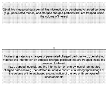
[00093] FIG. 11 shows an operation of the system in FIG. 2 based on
information
measured in both penetrated charged particles and trapped charged particles.
Based on the
measurements of the penetrated and stopped charged particles, the processing
unit combines
two or three types of measured data of trajectory changes of penetrated
charged particles
(e.g., penetrated muons), the information on stopped charged particles that
are trapped inside
the volume of interest (e.g., trapped muons), and the information on energy
loss of
penetrated charged particles (e.g., penetrated muons) to construct a
tomographic image of the
volume of interest. This process uses information of different processes
inside the volume of
interest to improve the fidelity and resolution of the final image for the
volume of interest and
to reduce the false detection. In one implementation, three types of
measurements can be
input into a processing algorithm to construct a single, maximum likelihood
material
tomographic map of the volume. As such, with the available three types of
measurements
from the system in FIG. 2, the generated tomographic image of the volume of
interest can be
more precise and accurate than the image from any of the measurements alone.
[00094] While this document contains many specifics, these should not be
construed as
limitations on the scope of any invention or of what may be claimed, but
rather as
descriptions of features specific to particular embodiments. Certain features
that are
described in this document in the context of separate embodiments can also be
implemented
in combination in a single embodiment. Conversely, various features that are
described in the
context of a single embodiment can also be implemented in multiple embodiments
separately
or in any suitable subcombination. Moreover, although features may be
described above as
acting in certain combinations and even initially claimed as such, one or more
features from a
27
CA 02735546 2011-02-28
WO 2010/025300 PCT/US2009/055253
claimed combination can in some cases be excised from the combination, and the
claimed
combination may be directed to a subcombination or variation of a
subcombination.
[00095] Thus, particular embodiments have been described. Variations and
enhancements
of the described embodiments and other embodiments can be made based on what
is
described and illustrated in this document.
28