Note: Descriptions are shown in the official language in which they were submitted.
CA 02735706 2011-02-28
DESCRIPTION
Title of the Invention
FUEL CELL POWER GENERATION SYSTEM
Technical Field
[0001] The present invention relates to a fuel cell power generation system
configured to activate an oxidant electrode of which catalytic activity is
deteriorated
by impurities contained in an oxidant gas, thereby enhancing efficiency of
power
generation and durability of a fuel cell.
Background Art
[0002] As shown in Fig. 7, a related art general fuel cell power generation
system includes a fuel cell 4 including an electrolyte 1 sandwiched between a
fuel
electrode 2 and an oxidant electrode 3, and generates electric power by
supplying
a fuel gas including at least hydrogen to the fuel electrode 2 and supplying
an
oxidant gas including at least oxygen to the oxidant electrode 3.
[0003] Air (an atmosphere) is usually used for an oxidant gas. However, air
contains various impurities in many cases. Some of the impurities are
substances
adhered to the oxidant electrode 3, to thus deteriorate activity of a catalyst
of the
oxidant electrode 3, and hinder occurrence of a chemical reaction required for
power generation, thereby decreasing an output voltage of the fuel cell 4.
[0004] In order to remove impurities adhered to the oxidant electrode 3, the
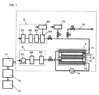
related art fuel cell power generation system includes, for example, an
external
power supply 5 except for a power generation circuit. The external power
supply
is electrically connected to the fuel cell 4, and a voltage is applied to the
fuel cell 4
during halting of power generation such that the oxidant electrode 3 to which
impurities remain adhered becomes a positive electrode. An electric potential
of
the oxidant electrode 3 is made higher than a natural electric potential for a
given
period of time, thereby oxidizing the impurities adhered to the oxidant
electrode 3
and desorbing the impurities from the oxidant electrode 3 (see Patent Document
1).
Related Art Documents
Patent Documents
1
CA 02735706 2011-02-28
[0005] Patent Document 1: JP-A-2005-259368
Summary of the Invention
Problem to be Solved by the Invention
[0006] However, a method for making the electric potential of the oxidant
electrode higher by use of the external' power supply involves a necessity for
providing an external power supply, such as a secondary cell, as well as
complicating a configuration of a system, thus raising a problem of non-
economic.
[0007] The present invention solves the problem of the related art, and an
object thereof is to provide a fuel cell power generation system capable of
removing
impurities adhered to an oxidant electrode without use of an external power
supply
and by a simple structure.
Means for Solving the Problem
[0008] The present invention provides a fuel cell power generation system
configured to generate electric power by a reaction of a fuel gas and an
oxidant gas,
said fuel cell power generation system comprising: a fuel cell comprising: a
fuel
electrode to which a fuel gas containing at !east hydrogen is supplied; an
oxidant
electrode to which an oxidant gas containing at least oxygen is supplied; and
an
electrolyte on which the fuel electrode and the oxidant electrode are formed;
an
output control unit configured to apply a predetermined voltage or more to the
oxidant electrode, with no electric power supplied to an outside of the fuel
cell
power generation system; and a determination unit configured to determine
timing
at which the output control unit applies the predetermined voltage or more.
[0009] According to the configuration of the present invention, the
determination unit determines the timing at which the output control unit
applies the
predetermined voltage or more before an irreversible voltage fall is caused by
impurities. Therefore, deterioration of efficiency of power generation, caused
by a
voltage fall, is prevented. Further, the output control unit which applies the
predetermined voltage or more to the oxidant electrode is activated with no
electric
power supplied to the outside of the fuel cell power generation system,
thereby
increasing the electric potential of the oxidant electrode without a necessity
for an
external power supply to thereby oxidize, desorb, and remove impurities
adhered to
the oxidant electrode. It is possible to provide a durability-enhanced fuel
cell
2
CA 02735706 2011-02-28
power generation system that enables activation of a fuel cell and maintenance
of
desired performance.
Advantages of the Invention
[0010] The present invention enables provision of a fuel cell power generation
system that can remove impurities adhered to an oxidant electrode without use
of
an external power supply and by means of a simple structure, to thus activate
a fuel
cell, and that exhibits superior efficiency of power generation and
durability.
Brief Description of the Drawings
[0011] Fig. 1 is a schematic view of a fuel cell power generation system
according to first through fifth embodiments of the present invention.
Fig. 2 is a flowchart showing a method for operating a fuel cell power
generation system of the second embodiment of the present invention.
Fig. 3(a) is a graph showing a behavior of a stack voltage of the fuel
cell power generation system when the fuel cell is not brought into an open
circuit
state, and Fig. 3(b) is a graph showing the behavior of the stack voltage of
the fuel
cell power generation system of the second embodiment of the present
invention.
Fig. 4 is a flowchart showing a method for operating a fuel cell power
generation system of a third embodiment of the present invention.
Fig. 5 is a flowchart showing a method for operating a fuel cell power
generation system of a fourth embodiment of the present invention.
Fig. 6 is a graph showing a behavior of a stack voltage appearing
when operation is performed under the fuel cell power generation system
operating
method.
Fig. 7 is a general schematic view of a related-art fuel cell power
generation system.
Mode for Carrying Out the invention
[0012] In a first invention, a fuel cell power generation system is configured
to
generate electric power by a reaction of a fuel gas and an oxidant gas, and
the fuel
cell power generation system includes: a fuel cell comprising: a fuel
electrode to
which a fuel gas containing at least hydrogen is supplied; an oxidant
electrode to
which an oxidant gas containing at least oxygen is supplied; and an
electrolyte on
3
CA 02735706 2011-02-28
which the fuel electrode and the oxidant electrode are formed; an output
control
unit configured to apply a predetermined voltage or more to the oxidant
electrode,
with no electric power supplied to an outside of the fuel cell power
generation
system; and a determination unit configured to determine timing at which the
output
control unit applies the predetermined voltage or more. According to the
present
invention, the determination unit determines timing at which the output
control unit
applies the predetermined voltage or more before an irreversible voltage fall
is
caused by impurities. Therefore, deterioration of efficiency of power
generation,
caused by a voltage fall, is prevented. Further, the output control unit which
applies the predetermined voltage or more to the oxidant electrode is
activated with
no electric power supplied to the outside of the fuel cell power generation
system,
thereby increasing the electric potential of the oxidant electrode without a
necessity
for an external power supply to thereby oxidize, desorb, and remove impurities
adhered to the oxidant electrode. It is possible to provide a durability-
enhanced
fuel cell power generation system that enables activation of a fuel cell and
maintenance of desired performance.
[0013] A second invention is based on the first invention, wherein the
predetermined voltage or more is a voltage higher than that applied during
normal
operation of the fuel cell. It is possible to obtain a fuel cell power
generation
system that can increase an electric potential of the oxidant electrode to
thereby
remove impurities adhered to the oxidant electrode through oxidation and in
turn
make it possible to make the fuel cell active.
[0014] A third invention is based on the first invention, wherein the
predetermined voltage or more is a voltage required for oxidizing impurities
adhered to the oxidant electrode. It is possible to obtain a fuel cell power
generation system that can increase an electric potential of the oxidant
electrode to
thereby remove impurities adhered to the oxidant electrode through oxidation
and
in turn make it possible to make the fuel cell active.
[0015] A fourth invention is based on any one of the first through third
inventions, wherein the predetermined voltage or more is a voltage obtained by
disconnecting a load from the fuel cell so as to bring the fuel cell into an
open circuit
state. It is possible to obtain a fuel cell power generation system that can
increase
an electric potential of the oxidant electrode to thereby remove impurities
adhered
4
CA 02735706 2011-02-28
to the oxidant electrode through oxidation and in turn make it possible to
make the
fuel cell active.
[0016] A fifth invention is based on any one of the first through third
inventions,
wherein the predetermined voltage or more is a voltage obtained by making a
load
of the fuel cell power generation system small. It is possible to obtain a
fuel cell
power generation system that can increase an electric potential of the oxidant
electrode to thereby remove impurities adhered to the oxidant electrode
through
oxidation and in turn make it possible to make the fuel cell active.
[0017] A sixth invention is based on any one of the first through fifth
inventions,
wherein the output control unit applies the predetermined voltage or more to
the
oxidant electrode in a state in which a fuel gas is supplied to the fuel
electrode, an
oxidant gas is supplied to the oxidant electrode, and no electric power is
supplied to
the outside of the fuel cell power generation system. It is possible to obtain
a fuel
cell power generation system that can increase an electric potential of the
oxidant
electrode to thereby remove impurities adhered to the oxidant electrode
through
oxidation and in turn make it possible to make the fuel cell active.
[0018] A seventh invention is based on any one of the first through fifth
inventions, wherein the output control unit applies the predetermined voltage
or
more to the oxidant electrode in a state in which supply of the fuel gas to
the fuel
electrode is stopped, supply of the oxidant gas to the oxidant electrode is
stopped,
and no electric power is supplied to the outside of the fuel cell power
generation
system. It is possible to obtain a fuel cell power generation system that can
increase an electric potential of the oxidant electrode to thereby remove
impurities
adhered to the oxidant electrode through oxidation and in turn make it
possible to
make the fuel cell active.
[0019] An eighth invention is based on any one of the first through seventh
inventions, wherein the determination unit comprises an power generation time
integration unit configured to integrate a power generation time of the fuel
cell, and
is configured to determine the timing at which the predetermined voltage or
more is
applied to the oxidant electrode based on an integrated time obtained by the
power
generation time integration unit. It is possible to obtain a fuel cell power
generation system capable of removing impurities adhered to the oxidant
electrode
by means of a very simple configuration; namely, integration of a power
generation
CA 02735706 2011-02-28
time, to thus make it possible to make the fuel cell active.
[0020] A ninth invention is based on any one of the first through seventh
inventions and further comprises an impurity concentration detection unit
configured to detect a concentration of impurities contained in the oxidant
gas,
wherein the determination unit calculates an integrated amount of impurities
supplied to the oxidant electrode based on the concentration of impurities
detected
by the impurity concentration detection unit and an amount of oxidant gas
supplied
to the oxidant electrode, and determines the timing at which the predetermined
voltage or more is applied to the oxidant electrode. As a result, it is
possible to
detect a concentration of impurities in the oxidant gas in real time and
remove the
impurities adhered to the oxidant electrode according to an actual integrated
amount of impurities, to thus make it possible to make the fuel cell active.
Therefore, it is possible to obtain a fuel cell power generation system that
exhibits
much superior efficiency of power generation and durability.
[0021] A tenth invention is based on any one of the first through ninth
inventions, wherein the impurities contained in the oxidant gas are sulfur
compounds. The sulfur compounds that poison the oxidant electrode, to thus
deteriorate the activity of the oxidant electrode, can be oxidized and removed
at a
neighborhood of a natural potential where the sulfur compounds are likely to
be
oxidized, by applying the predetermined voltage or more to the oxidant
electrode.
Therefore, it is possible to obtain a fuel cell power generation system that
exhibits
much superior efficiency of power generation and durability.
[0022] An eleventh invention is based on any one of the first through seventh
inventions and further comprises a voltage detection unit configured to detect
a
voltage of the fuel cell, wherein the determination unit calculates an
integrated
amount of impurities supplied to the oxidant electrode based on the voltage
detected by the voltage detection unit, and determines the timing at which the
predetermined voltage or more is applied to the oxidant electrode. As a
result,
even when means for directly detecting impurities is not available, an active
state of
the oxidant electrode is determined from a voltage of the fuel cell that
decreases in
response to the integrated amount of impurities. When the voltage is
determined
to be lower than a voltage acquired in normal times, the fuel call can be made
active. Therefore, the fuel cell power generation system can be further
simplified.
6
CA 02735706 2011-02-28
[0023] A twelfth invention is based on the eleventh invention, wherein, when a
number of times the predetermined voltage or more is applied to the oxidant
electrode exceeds a predetermined number of time and when the voltage detected
by the voltage detection unit falls below the predetermined voltage for a
given
period of time, the output control unit is configured to: stop power
generation of the
fuel cell and stops at least the supply of the oxidant gas so as to decrease
an
electric potential of the oxidant electrode to a predetermined electric
potential;
thereafter again supply the oxidant gas so as to bring the fuel cell into an
open
circuit state for a given period of time; and thereafter start power
generation of the
fuel cell. If the voltage is not recovered. even when the fuel cell is brought
into an
open circuit state in the middle of power generation, start-up operation is
stopped,
thereby decreasing the electric potential of the oxidant electrode from a high
electric potential (a natural electric potential) to a low electric potential,
thereby
removing various impurities through oxidation. Hence, the activity of the fuel
cell
can further be recovered.
[0024] A thirteenth invention is based on the fourth invention, wherein the
output control unit brings the fuel cell into the open circuit state while a
pressure of
the fuel gas supplied to the fuel electrode is maintained so as to become
lower than
a pressure of the oxidant gas supplied to the oxidant electrode. The amount of
hydrogen cross-leaking from the fuel electrode toward the oxidant electrode is
thereby decreased, whereby the electric potential of the oxidant electrode can
further be increased. Therefore, the impurities adhered to the oxidant
electrode
are further oxidized, so that the oxidant electrode can be made more active.
[0025] A fourteenth invention is based on the fourth invention, wherein the
output control unit brings the fuel cell into the open circuit state while a
pressure of
the fuel gas is maintained so as to become lower than a pressure of the
oxidant gas
supplied to the oxidant, electrode by decreasing a flow rate of the fuel gas
supplied
to the fuel electrode, and the flow rate of the fuel gas supplied to the fuel
electrode
is decreased only during a period in which power generation is temporarily
suspended. Therefore, the amount of hydrogen cross-leaking from the fuel
electrode to the oxidant electrode is decreased, so that the electric
potential of the
oxidant electrode can be increased further. Hence, impurities adhered to the
oxidant electrode are more oxidized, so that the oxidant electrode can be made
7
CA 02735706 2011-02-28
more active.
[0026] A fifteenth invention is based on the thirteenth invention and further
includes a fuel cell bypass line configured to bypass the fuel electrode of
the fuel
cell, wherein the output control unit brings the fuel cell into the open
circuit state
while the pressure of the fuel gas is maintained so as to become lower than
the
pressure of the oxidant gas supplied to the oxidant electrode by supplying a
part of
the fuel gas to the fuel cell bypass line thereby decreasing the flow rate of
the fuel
gas supplied to the fuel electrode. Further, a part of the fuel gas is
supplied to the
fuel cell bypass line only in a period during which power generation is
temporarily
suspended, to thus decrease the pressure of the fuel gas supplied to the fuel
electrode, and the fuel gas is supplied while a total amount of fuel gas
generated by
a fuel processing unit is maintained at a given level. Therefore, control of
the fuel
processing unit can be simplified.
[0027] A sixteenth invention is based on any one of the first through seventh
inventions, wherein the output control unit is configured to: control a supply
amount
of the fuel gas and supply amount of oxidant gas according to fluctuations in
a load
of the fuel cell, thereby controlling an output of the fuel cell; forcefully
decrease the
output of the fuel cell at the time determined by the determination unit,
thereby
decreasing the amount of fuel gas and the amount of oxidant gas to
predetermined
supply amounts under a predetermined output or less; and thereafter apply the
predetermined voltage or more to the oxidant electrode. With this
configuration,
the oxidant electrode is activated, and the power generation is stopped at a
low
output at which a consumed amount of fuel gas and a consumed amount of oxidant
gas are small. Therefore, the consumed amount of fuel gas and the consumed
amount of oxidant gas, which are not used for power generation, can be
minimized,
so that the fuel cell can be made active with superior efficiency.
[0028] Embodiments of the present invention are hereunder described by
reference to the drawings. The present invention shall not be limited by the
embodiments.
[0029] (First Embodiment)
Fig. 1 is a general schematic view of a fuel cell power generation
system of a first embodiment of the present invention.
[0030] A fuel cell power generation system of the first embodiment of the
8
CA 02735706 2011-02-28
present invention has a fuel cell 4 having a membrane electrode assembly 6.
The
membrane electrode assembly 6 includes a solid polymer electrolyte 1
(hereinafter
mentioned as an "electrolyte 1") that is made of perfluorocarbon sulfonate
polymer
exhibiting hydrogen ion conductivity and that is sandwiched between a fuel
electrode 2 and an oxidant electrode 3. The fuel cell power generation system
can generate electric power by supplying a fuel gas including at least
hydrogen to
the fuel electrode 2 and supplying an oxidant gas including at least oxygen to
the
oxidant electrode 3.
[0031] The fuel cell power generation system includes the fuel cell 4; a power
output unit that supplies a.c. electric power to at least an external load,
like an
inverter; and an internal load, like a power supply of auxiliary machinery and
a
control board.
[0032] Each of the fuel electrode 2 and the oxidant electrode 3 includes: a
catalyst layer that is formed from a mixture of a catalyst that is made by
means of
highly porous oxidation-resistant carbon carrying precious metal, like
platinum, and
a polymer electrolyte exhibiting hydrogen ion conductivity; and a gas
diffusion layer
that is stacked on the catalyst layer and that exhibits air permeability and
electron
conductivity. The fuel electrode 2 is formed from platinum-ruthenium alloy
catalyst
exhibiting CO resistance. The catalyst used for the fuel electrode 2 shall not
be
limited to the platinum-ruthenium alloy.
[0033] The gas diffusion layer is formed from carbon paper given water
repellency. The gas diffusion layer shall not be limited to the carbon paper
and
can be made of carbon cloth or nonwoven carbon fabric.
[0034] A pair of gaskets are placed in a neighborhood of the membrane
electrode assembly 6 made by sandwiching the electrolyte 1 between the fuel
electrode 2 and the oxidant electrode 3, in order to prevent mixing or leakage
of
gases. The fuel electrode 2 and the oxidant electrode 3 are sandwiched between
a pair of conductive carbon separator plates 71 and 72, thereby making up a
single
cell. The separator plate 71 having a gas flow channel supplies a fuel gas to
the
fuel electrode 2 and lets the fuel gas exit from the fuel electrode. The
separator
plate 72 having a gas flow channel supplies an oxidant gas to the oxidant
electrode
3 and lets the gas exit from the oxidant electrode.
[0035] Moreover, a plurality of single cells are layered, and a collector
plate,
9
CA 02735706 2011-02-28
f
an insulation plate, and an end plate are disposed on either end of the
stacked cells.
These plates are fastened by means of firmly fastening rods, thereby forming a
stack. A passageway for supplying and discharging cooling water is laid
between
the cells. In order to prevent dissipation of heat to the outside of the stack
and
maintain a stable temperature, a heating insulating material is disposed
around the
stack.
[0036] A fuel processing unit 8 for supplying a fuel gas and an oxidant gas
supply unit 9 for supplying an oxidant gas are connected to the fuel cell 4
having
the foregoing configuration, thereby constituting a fuel cell power generation
system.
[0037] The fuel processing unit 8 comprises a desulfurization unit 81 that
reforms a source gas, such as a hydrocarbon-containing city gas like methane,
to
thus supply a fuel gas containing hydrogen, and that adsorbs and removes a
sulfur
compound contained in odorant; a reforming unit 82 that reforms a
hydrocarbon-containing source gas, like methane; a CO shift unit 83 that
shifts
carbon monoxide (CO) caused by a reforming reaction; and a CO removal unit 84
that additionally, selectively removes CO through oxidation.
[0038] After having first undergone desulfurization in the desulfurization
unit
81, the source gas is reformed by the reforming unit 82, to thus turn into a
fuel gas
containing hydrogen. When methane is used as a source gas, a reaction
represented by (Chemical Formula 1) occurs in the reforming unit 82 with
generation of steam, whereupon about 10% of CO develops along with hydrogen
that is a fuel gas.
[0039] [Chemical Formula 1]
CH4 + H2O -* CO + 3H2
[0040] A platinum catalyst included in the fuel electrode 2 is poisoned by a
nominal amount. of CO in an operating temperature range of the fuel cell 4.
Activity of the catalyst resultantly decreases. Therefore, as represented by
(Chemical Formula 2), CO developed in the reforming unit 82 is shifted into
carbon
dioxide by the CO shift unit 83. The concentration of carbon dioxide drops to
about 5000 ppm. Since the CO removal unit 84 disposed at a downstream
position oxides hydrogen of the fuel gas as well as CO, the CO shift unit 83
must
decrease the concentration of CO to the minimum possible level.
CA 02735706 2011-02-28
[0041] [Chemical Formula 2]
CO + H2O -> CO2 + H2
10042] The CO removal unit 84 selectively oxides the remaining CO as
represented by (Chemical Formula 3) by means of the air taken in from the
atmosphere by a selective oxidation air supply unit 85. The concentration of
CO
decreases to about 10 ppm or less at. which deterioration of activity of the
catalyst
of the fuel electrode 2 can be prevented.
[0043] [Chemical Formula 3]
CO + 1/202 -> CO2
[0044] The fuel processing unit 8 is not limited to the steam reforming
technique, and another hydrogen generation technique, like an automatic
thermal
technique can also be adopted.
[0045] Further, there is adopted a configuration in which an air-bleeding unit
for supplying air to the fuel electrode 2 that is in the middle of power
generation,
is disposed in front of the fuel electrode 2 and in which slightly-remaining
influence
of CO is further lessened by mixing about 1 to 2% of air into the fuel gas
generated
by the fuel processing unit 8. The air-bleeding unit 10 can also be omitted
according to the concentration of CO contained in the fuel gas.
[0046] An oxidant gas supply unit 9 is made up of a blower 91 that takes in an
oxidant gas; an impurity removal unit 92 that removes impurities from the
oxidant
gas; and a humidifier 93 that humidifies the oxidant gas. The oxidant gas
supply
unit 9 supplies a humidified oxidant gas to the oxidant electrode 3 of the
fuel cell 4.
The oxidant gas is a generic designation of a gas including at least oxygen
(or a
gas capable of supplying oxygen). For instance, atmosphere (air) can be
mentioned as the gas.
[0047] Operation of the fuel cell 4 having the foregoing configuration is now
described. A fuel gas is supplied to the fuel electrode 2, and an oxidant gas
is
supplied to the oxidant electrode 3, whereupon a load is connected to the fuel
cell.
Thereby, hydrogen contained in the fuel gas supplied to the fuel electrode 2
discharges electrons at a boundary surface between the catalyst layer of the
fuel
electrode 2 and the electrolyte, to thus become hydrogen ions, as indicated by
a
reaction formula (Chemical Formula 4).
[0048] [Chemical Formula 4]
11
CA 02735706 2011-02-28
H2->2H++2e
[0049] Hydrogen ions migrate to the oxidant electrode 3 through the
electrolyte 1 and receives electrons at the boundary surface between the
catalyst
layer of the oxidant electrode 3 and the electrolyte. The thus-received
electrons
react with oxygen contained in the oxidant gas supplied to the oxidant
electrode 3,
thereby generating water. The reaction formula is represented as illustrated
by
(Chemical Formula 5).
[0050] [Chemical Formula 5]
1/202 + 2H+ + 2e -> H2O
[0051] All reactions are represented by (Chemical Formula 6).
[0052] [Chemical Formula 6]
H2 + 1 /202 -> H2O
[0053] A flow of electrons flowing through the load at this time can be
utilized
as electric energy of a d.c. Further, since the series of reactions are
thermal
reactions, reaction heat can be utilized as thermal energy.
[0054] In Fig. 1, an output control unit 11 controls an output from the fuel
cell 4
according to fluctuations in load. When a larger amount of electric power
generated is required as a result of an increase in the load of the fuel cell
4, the
amount of source gas supplied to the fuel processing unit 8 is increased,
thereby
increasing the amount of fuel gas generated. Further, a capability value of
the
blower 91 is increased, thereby increasing the supply amount of oxidant gas.
[0055] Conversely, the power generation system is configured in such a way
that, when the amount of electric power generated is not much required, the
supply
amount of fuel gas or oxidant gas is decreased, thereby decreasing the output.
[0056] Incidentally, there are many cases where the atmosphere includes a
variety of impurities. For instance, the atmosphere includes sulfur compounds,
such as sulfur dioxide included in a volcano or a combustion exhaust gas, a
nitrogen oxide much included in combustion exhaust gases from a factory and an
automobile, and ammonia that is a malodorous component.
[0057] The impurities adversely affect the fuel cell 4. When reached the
oxidant electrode 3 while mixed in the oxidant gas, the impurities adhere
(adsorb)
to a catalyst included in the oxidant electrode 3, thereby impeding a chemical
reaction required to generate electric power. For this reason, an output of
the fuel
12
CA 02735706 2011-02-28
cell 4 is sometimes decreased. Of the impurities, the sulfur compound exhibits
comparatively strong adsorption force. When a large amount of sulfur compound
is accumulated, difficulty is encountered in removing the sulfur compound,
which in
turn becomes a cause of deterioration of efficiency of power generation or
durability
of the fuel cell 4.
[0058] In the meantime, the oxidation reaction of the impurities can be
promoted according to a polarity potential of the oxidant electrode 3. A
reaction of
water with air can easily desorb the impurities adhered to the oxidant
electrode 3
from the oxidant electrode 3.
[0059] The fuel cell power generation system of the embodiment has at least
the fuel electrode 2 that is supplied with a fuel gas including at least
hydrogen; the
oxidant electrode 3 that is supplied with an oxidant gas including at least
oxygen;
the fuel cell 4 that includes the electrolyte 1 having the fuel electrode 2
and the
oxidant electrode 3; the output control unit 11 that applies a predetermined
voltage
or more to the oxidant electrode 3 in a state in which electric power is not
supplied
to the outside of the fuel cell power generation system; and a determination
unit 12
that determines timing for applying the predetermined voltage or more from the
output control unit 11.
[0060] An external load (not shown) of the fuel cell power generation system
is equipped with a power output unit (not shown), such as an inverter for
supplying
a.c. power. The fuel cell 4 supplies electric power to the external load and
internal
load (not shown), such as auxiliary machinery included in the fuel cell power
generation system or a power supply of a control substrate. A state in which
electric power is not supplied to the outside of the fuel cell power
generation
system is a state in which the external load is disconnected while all of the
internal
loads or some of the internal loads remain intact.
[0061] In the configuration of the present embodiment, the determination unit
12 determines timing at which the output control unit 11 is to apply a
predetermined
voltage or more before an irreversible voltage fall is caused by impurities,
according
to a result of a determination made by the determination unit 12. Therefore,
deterioration of efficiency of power generation, which would otherwise be
caused
by a voltage fall, is prevented. Further, the output control unit 11 which
applies a
predetermined voltage or more to the oxidant electrode is activated with no
electric
13
CA 02735706 2011-02-28
power supplied to the outside of the fuel cell power generation system,
thereby
increasing the electric potential of the oxidant electrode 3 without a
necessity for an
external power supply to thereby oxidize, desorb, and remove impurities
adhered to
the oxidant electrode. It is possible to provide a durability-enhanced fuel
cell
power generation system that enables activation of the fuel cell 4 and
maintenance
of desired performance.
[0062] The predetermined voltage or more is a voltage that is higher than that
acquired during normal operation of the fuel cell 4. It is possible to obtain
a fuel
cell power generation system that increases the electric potential of the
oxidant
electrode 3 to thus remove the impurities adhered to the oxidant electrode 3
through oxidation, thereby making it possible to make the fuel cell 4 active.
Further, the predetermined voltage or more is a voltage required to
oxidize the impurities adhered to the oxidant electrode 3. It is possible to
obtain a
fuel cell power generation system that makes it possible to remove the
impurities
adhered to the oxidant electrode 3 through oxidation, thereby making the fuel
cell 4
active.
[0063] The predetermined voltage or more is a voltage obtained by making a
load of the fuel cell power generation system low. It is possible to obtain a
fuel cell
power generation system that makes it possible to bring the oxidant electrode
3 into
a high potential, to thus remove the impurities adhered to the oxidant
electrode 3
through oxidation and to thereby make the fuel cell 4 active.
[0064] Further, the predetermined voltage or more is a voltage obtained when
the fuel cell 4 is brought into an open circuit state as a result of the load
on the fuel
cell being disconnected. It is possible to obtain a fuel cell power generation
system that makes it possible to bring the oxidant electrode 3 into a high
potential,
to thus remove the impurities adhered to the oxidant electrode 3 through
oxidation
and to thereby make the fuel cell 4 active.
[0065] An explanation is hereunder given to a configuration for oxidizing and
removing the impurities adhered to the oxidant electrode 3 by use of the
predetermined voltage or more that is acquired when the load of the fuel cell
4 is
brought into an open circuit state as a result of the load on the fuel cell
being
disconnected.
[0066] An electrode potential at which an oxidation reaction is promoted
14
CA 02735706 2011-02-28
r
changes according to types of impurities. A sulfur compound, such as sulfur
dioxide, is likely to be oxidized at an electrode potential that is higher
than that
acquired during generation of electric power. The present inventors found the
followings. Specifically, there is set an open circuit state in which the load
is
disconnected from the fuel cell 4 while the output control unit 11 is
supplying a fuel
gas to the fuel electrode 2 and an oxidant gas to the oxidant electrode 3. An
electrode potential that is higher than an electrode potential achieved during
power
generation of the fuel cell is achieved even at a natural potential achieved
in the
open circuit state. Most of the sulfur compound adhered to the oxidant
electrode 3
can be oxidized, and the sulfur compound oxidized by the oxidant gas being
continually supplied can be desorbed and removed from the oxidant electrode 3.
[0067] Therefore, in the present invention, an attention is paid to the sulfur
compound that causes an irreversible voltage fall when accumulated to a
certain
extent. The fuel cell 4 is brought into an open state at a small integrated
amount
of sulfur compound which does not cause an irreversible voltage fall, thereby
bringing the oxidant electrode 3 into a high electric potential (a natural
electric
potential). Thus, the sulfur compound adhered to the oxidant electrode 3 is
oxidized and removed, thereby activating the fuel cell 4.
[0068] In relation to a threshold value of an integrated amount of impurity
supplied to the oxidant electrode 3 when the fuel cell 4 is brought into an
open
circuit state, a limit amount that does not cause an irreversible voltage fall
and at
which the voltage recovers so long as the natural potential is retained for
one
second to ten minutes is previously determined through a test. Further, an
integrated amount achieved before the limit amount is taken as a threshold
value.
[0069] So long as the threshold value of the integrated amount of impurity is
a
value that meets the objective of the limit amount, a direct amount of
impurities can
be the threshold value or an indirect amount equivalent to the amount of
impurities
can also be the threshold value. There is provided the determination unit 12
that
determines a period at which the fuel cell is brought into an open circuit
state,
according to the threshold value for the integrated amount of impurities.
[0070] According to the configuration of the present embodiment, the
determination unit 12 determines a period at which the fuel cell is brought
into an
open circuit state before the impurities cause an irreversible voltage fall.
Hence, a
CA 02735706 2011-02-28
fall in efficiency of power generation, which would otherwise be caused by a
voltage fall, does not occur. Moreover, the output control unit 11 that brings
the
fuel cell 4 into an open circuit state at a period determined by the
determination unit
12 brings the oxidant electrode 3 into a high electric potential without a
necessity
for an external power supply. Impurities adhered to the oxidant electrode 3
are
oxidized, and the impurities oxidized by the oxidant gas are desorbed and
removed.
Thus, it is possible to obtain a durability-enhanced fuel cell power
generation
system that can activate the fuel cell 4 and maintain desirable performance.
[0071] A specific example for obtaining a threshold value for an integrated
amount of impurities is described hereunder.
[0072] The integrated amount of impurities is added with elapse of a power
generation time of the fuel cell 4. Accordingly, the determination unit 12 has
a
power generation time integration unit (not shown) that integrates a power
generation time of the fuel cell 4. When the integration time acquired by the
power
generation time integration unit has become equal to the threshold value for
the
integrated amount of impurities, the determination unit 12 determines timing
at
which the fuel cell 4 is to be brought into an open circuit state. The output
control
unit 11 disconnects, at a period determined by the determination unit 12, the
load of
the fuel cell 4 with the fuel gas supplied to the fuel electrode 2 and with
the oxidant
gas supplied to the oxidant electrode 3, thereby bringing the fuel cell into
an open
circuit state.
[0073] According to the present embodiment, it is possible to obtain a fuel
cell
power generation system that enables activation of the fuel cell 4 by removing
the
impurities adhered to the oxidant electrode 3 according to a very simple
configuration that integrates a power generation time.
[0074] In the foregoing explanation, the output control unit 11 supplies the
fuel
gas to the fuel electrode 2 and the oxidant gas to the oxidant electrode 3,
thereby
bringing the fuel cell into an open circuit state. However, the essential
requirement is to apply a predetermined voltage or more to the oxidant
electrode 3
with no electric power supplied to the outside of the fuel cell power
generation
system and without bringing the fuel cell into an open circuit state. It is
possible to
obtain a fuel cell power generation system that brings the oxidant electrode 3
into a
high electric potential to thereby remove the impurities adhered to the
oxidant
16
CA 02735706 2011-02-28
electrode 3 through oxidation, thereby activating the fuel cell.
[0075] The output control unit 11 can also be configured in such a way that,
with the supply of fuel gas to the fuel electrode 2 and the supply of oxidant
gas to
the oxidant electrode 3 stopped and with no electric power supplied to the
outside
of the fuel cell power generation system, the predetermined voltage or more is
supplied to the oxidant electrode 3. Even in a state which supplying the fuel
gas
and the oxidant gas is suspended, a predetermined voltage is still applied by
the
gases supplied to the fuel electrode 2 and to the oxidant electrode 3
immediately
before halting the gas supply.
[0076] (Second Embodiment)
Fig. 1 shows a general configuration of a fuel cell power generation
system of a second embodiment of the present invention.
[0077] The power generation time integration unit provided in the
determination unit 12 of the first embodiment is deleted from the fuel cell
power
generation system of the second embodiment of the present invention. The
system is provided with an impurity concentration detection unit 13 for
detecting a
concentration of impurities included in the oxidant gas instead. The other
constituent elements are assigned the same reference numerals, and their
explanations are omitted for brevity.
[0078] The determination unit 12 connected to the output control unit 11
computes a time that will elapse before the fuel cell 4 is brought into an
open state,
from a concentration of impurities in a flow subsequent to the impurity
removal unit
92 estimated from an impurity removal ratio of the impurity removal unit 92, a
supply amount of oxidant gas, and an integrated amount of impurities supplied
to
the oxidant electrode. The determination unit 12 can send to the output
control
unit 11 a timing command for bringing the fuel cell 4 into an open circuit
state.
[0079] In relation to the concentration of impurities in the atmosphere, an
average concentration of impurities acquired in normal times is previously
input to
the determination unit 12, by reference to impurity information about a
location
where the fuel cell power generation system is installed. Alternatively, the
concentration of impurities in the atmosphere can be automatically acquired by
way
of a communication unit, the Internet, as required. In the present embodiment,
the
fuel cell power generation system is equipped with the impurity concentration
17
CA 02735706 2011-02-28
detection unit 13 and configured so as to detect a real-time concentration of
impurities in the oxidant gas acquired in the installation environment. A
sulfur
dioxide gas sensor capable of detecting sulfur dioxide is used for the
impurity
concentration detection unit 13.
[0080] An operation sequence of the fuel cell power generation system of the
present invention is now described by reference to a flowchart shown in Fig.
2.
[0081] First, the determination unit 12 calculates an integrated amount of
impurities (sulfur dioxide) supplied to the oxidant electrode, from the
concentration
of sulfur dioxide detected by the impurity concentration detection unit 13, a
rate of
removal of sulfur dioxide achieved in the impurity removal unit 92, and a
amount of
oxidant gas supplied to the oxidant electrode 3 by the blower 91 from
initiation of
power generation, thereby determining timing at which the fuel cell 4 is to be
brought into an open circuit state (step S101).
[0082] It is now determined whether or not the integrated amount of impurities
determined in step 101 is larger than a threshold value of an integrated
amount of
impurities that has previously been determined by way of experiment (step
102).
[00"03] When the integrated amount of impurities is in excess of the threshold
value, the output control unit 11 maintains an open circuit state (for about
one
second to ten minutes) in which the load is disconnected from the fuel cell 4
with
the fuel gas supplied to the fuel electrode 2 and the oxidant gas supplied to
the
oxidant electrode 3 (step 103). Since power generation of the fuel cell is
consequently brought into a halt state, power generation is depicted as being
halted in Fig. 2.
[0084] When the fuel cell is brought into the open state for about one second
to ten minutes, the load is connected, and power generation is started again
(steps
104 and 105).
[0085] As in the first embodiment, activity of the fuel cell 4 is recovered as
a
result of having been brought into an open circuit state, so that efficiency
of power
generation and durability of the fuel cell power generation system can be
enhanced.
[0086] Carbon contained in a catalyst layer of the oxidant electrode 3
becomes more susceptible to corrosion and oxidation at a high electric
potential, to
thus become deteriorated. However, in the fuel cell power generation system of
18
CA 02735706 2011-02-28
f
the present embodiment, the electric potential of the electrodes increases up
to a
natural potential as a result of the fuel cell being brought into an open
circuit state.
Therefore, oxidation of carbon making up the catalyst layer can be prevented.
[0087] In order to ascertain an advantage of the fuel cell power generation
system of the embodiment having the foregoing configuration, a simulation was
actually carried out with an oxidant gas including impurities (sulfur dioxide)
supplied
to the oxidant electrode 3 of the fuel cell 4. The concentration of sulfur
dioxide
supplied was set to a concentration achieved after removal of an average
concentration of impurities included in an actual atmosphere by the impurity
removal unit 92. Fig. 3 shows a test result.
[0088] Fig. 3(a) shows a shift in stack voltage occurred when power
generation is performed with the fuel cell not held in an open circuit state
and with
impurities being supplied. The drawing shows that a voltage (designated by
solid
circles) achieved after elapse of a given time since power generation was
started
gradually decreases. A conceivable reason for this is that sulfur dioxide in
the
oxidant gas is gradually built up in the oxidant electrode 3, thereby
poisoning the
catalyst, so that a chemical reaction is hindered, thereby causing
deterioration of
activity of the fuel cell.
[0089] In the meantime, Fig. 3(b) shows that the stack voltage acquired under
the operating method of the present invention shifts constantly without
involvement
of occurrence of a decrease in the voltage (designated by solid circles in the
drawing) after elapse of a given time since power generation was started, as a
result of the fuel cell being periodically brought into an open circuit state
in the
middle of power generation according to the integrated amount of impurities.
[0090] Consequently, the fuel cell power generation system of the present
embodiment can detect the concentration of impurities in oxidant gas in real
time
and remove the impurities adhered to the oxidant electrode 3 through oxidation
according to the integrated amount of actual impurities, thereby activating
the fuel
cell 4. Therefore, efficiency of power generation and durability of the fuel
cell 4
can be enhanced.
[0091] (Third Embodiment)
Fig. 1 shows a general configuration of a fuel cell power generation
system of a third embodiment of the present invention.
19
CA 02735706 2011-02-28
[0092] The impurity concentration detection unit 13 shown in Fig. 1 is deleted
from the fuel cell power generation system of the third embodiment of the
present
invention. The fuel cell power generation system is equipped with a voltage
detection unit 14 that detects a voltage of the fuel cell 4. When a voltage
detected
by the voltage detection unit 14 has fallen below, for a given period of time,
a
predetermined voltage determined by an output of the fuel cell 4, an
integrated time
output from the power generation time integration unit, and the time elapsed
since
power generation was started, the determination unit 12 determines the time as
timing for bringing the fuel cell 4 into an open circuit state. The fuel cell
power
generation system of the third embodiment is analogous to the fuel cell power
generation system of the second embodiment except the above. Detailed
explanations are given to a difference between the second embodiment and the
third embodiment.
[0093] As mentioned above, the voltage of the fuel cell 4 is decreased by
impurities. So long as the concentration of impurities is equal to or less
than a
predetermined concentration, the voltage shifts according to the
concentration.
For this reason, so long as the voltage is monitored, it is possible to
determine the
concentration of impurities and an integrated amount of impurities to a
certain
extent even when means, like the impurity concentration detection unit 13, is
not
provided.
[0094] Consequently, if consideration is given to a voltage that gradually
decreases in conjunction with durability regardless of impurities and to a
voltage
that gradually decreases for reasons of a recovery effect immediately after
start-up
of the fuel cell power generation system, a threshold value equivalent to the
integrated amount of impurities can be determined from the voltage detected by
the
voltage detection unit 14.
[0095] In the third embodiment, the determination unit 12 calculates, from the
voltage detected by the voltage detection unit 14, an integrated amount of
impurities that are included in the oxidant gas and that are supplied to the
oxidant
electrode 3. Further, the determination unit determines timing at which the
fuel
cell 4 is to be brought into an open circuit state. Even when the impurity
concentration detection unit 13 is not provided, the active state of the
oxidant
electrode 3 is determined from the voltage of the fuel cell 4 that decreases
in
CA 02735706 2011-02-28
response to the integrated amount of impurities. When the voltage is lower
than
the voltage of the fuel cell achieved in normal times, the fuel cell 4 is
brought into an
open circuit state. Therefore, the fuel cell power generation system can
further be
simplified.
[0096] Further, there is realized the following configuration. Specifically,
when the number of times the fuel cell 4 is brought into an open circuit state
since
power generation was started has surpassed a predetermined number of times and
when the voltage detected by the voltage detection unit 14 still falls below
the
predetermined voltage for a given period of time, the output control unit 11
disconnects the load from the fuel cell 4, thereby forcefully stopping power
generation of the fuel cell 4. After the electric potential of the oxidant
electrode 3
is decreased to a predetermined electric potential by suspending at least an
oxidant gas supply, the fuel cell 4 is re-started and brought into an open
circuit state
for a given period of time, and power generation is subsequently resumed.
[0097] It is not always necessary to stop the fuel gas.supply. It is desirable
to avoid stopping the fuel gas supply from the viewpoint of preventing useless
energy consumption, which would otherwise arise when the fuel processing unit
8
that remains stably hot at a high temperature is deactivated.
[0098] Fig. 4 shows a flowchart of operation of a method for operating the
fuel
cell power generation system of the third embodiment of the present invention.
[0099] First, the voltage detection unit 14 monitors the voltage of the fuel
cell 4
(step 201).
[0100] The determination unit 12 determines whether or not the voltage
detected by the voltage detection unit 14 has become lower than a threshold
value
that is a voltage acquired at timing when the integrated amount of impurities,
which
has not yet reached a limit amount at which an irreversible voltage fall
occurs, has
adhered to the oxidant electrode 3. The determination unit 12 determines
timing
at which the fuel cell 4 is to be brought into an open circuit state (step
202). The
output control unit 11 maintains, for a predetermined period of time (about
one
second to 10 minutes), an open circuit state in which the load is disconnected
from
the fuel cell 4 with the fuel gas supplied to the fuel electrode 2 and the
oxidant gas
supplied to the oxidant electrode 3 when the voltage detected by the voltage
detection unit 14 is under the threshold value (step 203). Since power
generation
21
CA 02735706 2011-02-28
of the fuel cell is consequently brought into a halt, power generation is
depicted as
being halted in Fig. 4.
[0101] After the fuel cell has been held in an open circuit state for about
one
second to ten minutes, the load is again connected to the fuel cell 4, thereby
releasing the fuel cell from the open circuit state and commencing power
generation (steps 204 and 205).
[0102] The number of times the fuel cell is brought into an open circuit state
since power generation was started is counted up (step 206). In a case where
the
voltage is determined not to increase even when the count has exceeded a
predetermined number of times the fuel cell is brought into an open circuit
state (a
threshold value) (step 207), the fuel cell shifts to a normal power generation
stop
mode in which the load is disconnected from the fuel cell 4 to thereby
forcefully stop
the fuel cell.
[0103] Power generation is first stopped (step 208), and at least the oxidant
gas supply is subsequently stopped (step 209).
[0104] Since hydrogen that is a fuel gas is present around the fuel electrode
2,
the voltage of the stack can be deemed to be substantially equal to the
electric
potential of the oxidant electrode 3. When the electric potential of the
oxidant
electrode 3 has decreased to about OV to 0.2V or when a time equivalent to a
period of decrease in electric potential has elapsed (step 210), the oxidant
gas
supply to the oxidant electrode 3 is resumed (step 211). When the oxidant gas
supply is started, the electric potential of the oxidant electrode 3 starts
increasing,
to thus reach the natural electric potential.
[0105] The load is connected to the fuel cell 4, and power generation is
resumed (step 212).
[0106] According to the present embodiment, if the voltage is not recovered
even when the fuel cell has been brought into an open circuit state a
plurality of
times or more during power generation, the electric potential of the oxidant
electrode 3 is decreased from a high electric potential (the natural electric
potential)
to a low electric potential by means of deactivating the fuel cell. The
oxidant
electrode 3 thus changes from an oxidized state to a reduced state, so that
the
activity of the oxidant electrode 3 can be recovered.
[0107] As a result of the fuel cell being brought into an open circuit state,
the
22
CA 02735706 2011-02-28
impurities adhered to the oxidant electrode 3 are oxidized. Hence, the
thus-oxidized impurities can be dissolved in condensed water caused by
deactivation or water generated during power generation, and resultant
dissolved
impurities can be discharged out of the system. Thus, influence of the
impurities
can further be lessened by combination of the open circuit state with
deactivation.
[0108] (Fourth Embodiment)
Fig. 1 is a general configuration of a fuel cell power generation system
of a fourth embodiment of the present invention.
[0109] The fuel cell power generation system of the fourth embodiment of the
present invention is based on the fuel cell power generation system of the
second
embodiment. The fuel cell power generation system of the present embodiment is
identical with the fuel cell power generation system of the second embodiment
except the followings. Namely, the output control unit 11 disconnects the load
from the fuel cell 4 for a predetermined period of time with the pressure of
the fuel
gas supplied to the fuel electrode 2 maintained lower than the pressure of the
oxidant gas supplied to the oxidant electrode 3, thereby bringing the fuel
cell 4 into
an open circuit state to thus activate the oxidant electrode 3. Detailed
descriptions
are given to a difference between the second embodiment and the fourth
embodiment.
[0110] In the configuration of the embodiment, the determination unit 12 of
any of the first through third embodiments determines timing when the fuel
cell is
brought into an open circuit state before an irreversible voltage fall is
caused by
impurities. The pressure of the fuel gas is made lower than the pressure of
the
oxidant gas at the timing determined by the determination unit 12.
Subsequently,
the output control unit 11 disconnects the load from the fuel cell 4 for a
predetermined period of time, thereby bringing the fuel cell 4 into an open
circuit
state.
[0111] In the present embodiment, the pressure of the fuel gas is made lower
than the pressure of the oxidant gas, thereby causing a decrease in amount of
hydrogen cross-leaking from the fuel electrode 2 toward the oxidant electrode
3.
The electric potential of the oxidant electrode 3 can be further increased, so
that
the impurities adhered to the oxidant electrode 3 become more susceptible to
oxidation and that the oxidant electrode can be activated to a much greater
extent.
23
CA 02735706 2011-02-28
[0112] Pressure of the fuel gas supplied to the fuel electrode 2 is decreased
by means of decreasing the flow rate of the fuel gas.
[0113] As shown in Fig. 1, a fuel cell bypass line 15 is provided so as to
bypass the fuel electrode 2 of the fuel cell 4. Only when the fuel cell 4 is
activated,
a portion of fuel gas is supplied to the fuel cell bypass line 15, thereby
decreasing
the amount of fuel gas supplied to the fuel electrode 2. The pressure of the
fuel
gas is maintained so as to become lower than the pressure of the oxidant gas
supplied to the oxidant electrode 3. The fuel gas generated by the fuel
processing
unit 8 can be supplied with a constantly-maintained total amount of the fuel
gas, so
that control of the fuel processing unit 8 can be simplified.
[0114] (Fifth Embodiment)
Fig. 1 shows a general configuration of a fuel cell power generation
system of a fourth embodiment of the present invention.
[0115] The fuel cell power generation system of the fifth embodiment of the
present invention is analogous to the fuel cell power generation system of the
second embodiment except the following point. The output control unit 11
forcefully decreases an output of the fuel cell 4 at the time that is
determined by the
determination unit 12 as timing for bringing the fuel cell 4 into an open
circuit state.
After the amount of fuel gas and the amount of oxidant gas have decreased to
their
predetermined supply amounts at a predetermined output level or less, the load
is
disconnected from the fuel cell 4, to thus bring the fuel cell 4 into an open
circuit
state. Detailed descriptions are given to a difference between the present
embodiment and the second embodiment.
[0116] An operation sequence of the fuel cell power generation system of the
fifth embodiment of the present invention is described by reference to a
flowchart of
Fig. 5.
[0117] First, the determination unit 12 calculates an integrated amount of
impurities from the concentration of sulfur dioxide detected by the impurity
concentration detection unit 13, a ratio of sulfur dioxide removed by the
impurity
removal unit 92, and the amount of oxidant gas supplied from the blower 91 to
the
oxidant electrode 3 since power generation was started (step 301).
[0118] A determination is now made as to whether or not the integrated
amount determined in step 301 is greater than the threshold value for the
24
CA 02735706 2011-02-28
integrated amount previously determined by way of experiment (step 302).
[0119] If the integrated amount is in excess of the threshold value, the
output
of the fuel cell 4 is forcefully decreased. The supply amount of the fuel gas
and
the supply amount of the oxidant gas are correspondingly decreased (step 303).
The output, the supply amount of fuel gas, and the supply amount of oxidant
gas
are set to the minimum output and corresponding supply amounts of the fuel
cell
power generation system.
[0120] When the supply amount of fuel gas and the supply amount of oxidant
gas have reached threshold values, there is maintained for a given period of
time
(about one second to ten minutes) an open circuit state in which the load is
disconnected from the fuel cell 4 with the fuel gas supplied to the fuel
electrode 2
and the oxidant gas supplied to the oxidant electrode 3 (steps 304 and 305).
As a
consequence, power generation of the fuel cell is brought into a halt. Hence,
power generation is depicted as being halted in Fig. 5.
[0121] After the fuel cell has been held in the open circuit state for about
one
second to ten minutes, the load is again connected to the fuel cell 4, thereby
stopping the open circuit state of the fuel cell and starting power generation
(steps
306 and 307).
[0122] According to the fuel cell power generation system of the fourth
embodiment of the invention, power generation is halted at a small output at
which
the consumed amount of fuel gas and the consumed amount of oxidant gas are
small. Therefore, the amount of fuel gas and the amount of oxidant gas that
are
consumed but not used for power generation can be minimized, so that the fuel
cell
can be made active with superior efficiency.
[0123] Fig. 6 shows a behavior of the stack voltage appearing before and
after the fuel cell is brought into an open circuit state. After the time "t"
elapsed
before the integrated amount of impurities reaches the limit amount at which a
voltage fall occurs since power generation was started, the output of the fuel
cell 4
is decreased, and the supply amount of fuel gas and the supply amount of
oxidant
gas are also decreased simultaneously. The voltage of the stack has increased
at
this time. Further, immediately after the stack voltage increased, the fuel
cell is
brought into an open circuit state in which the load is disconnected from the
fuel cell
4 with the fuel gas supplied to the fuel electrode 2 and with the oxidant gas
supplied
CA 02735706 2011-02-28
to the oxidant electrode 3. Further, the stack voltage is again increased, and
the
voltage of the open circuit is held for about 10 seconds.
[0124] The load is later reconnected, and the supply amount of fuel gas and
the supply amount of oxidant gas are increased in order to return the fuel
cell into
the original state of power generation, thereby increasing the output of the
fuel cell
4. Similar activation processing is again performed after elapse of time "t"
from a
point in time when the fuel cell was brought into an open circuit state, to
thus
become active.
[0125] The integrated amount of impurities achieved at time "t" remains
constant. Since the constant integrated amount of impurities are thoroughly
removed by the same operation, to thus make the fuel cell active, a fuel cell
power
generation system exhibiting high resistance to impurities can be produced.
[0126] Incidentally, the fuel cell power generation system uses a city gas as
a
source gas. For this reason, a gas supply line is sometimes equipped with a
safety device that is called a microcomputer meter. The microcomputer meter is
a
gas meter that monitors a flow rate of the gas and has a capability of
automatically
shutting off the supply of gas in case of escape of gas.
[0127] For instance, when the consumed amount of the gas remains constant
for a given period of time and when no variations occurred in a constant flow
rate, a
gas is determined to escape and therefore shut off. In the meantime, there is
a
high probability of a fuel cell power generation system being continually used
when
compared with another gas apparatus. When electric power is generated at a
given output, gas may be shut off in spite of no escape of gas.
[0128] Forceful shutoff of gas will arouse an apprehension that an energy
saving characteristic will be deteriorated and that durability of an apparatus
will be
affected. For these reasons, there is a known technique of forcefully changing
and decreasing an output of a fuel cell power generation system when power
generation is continually performed at a given output for a given period of
time or
more, thereby changing the amount of gas used.
[0129] When the predetermined period of time during which electric power is
continually generated at a given output is shorter than the time "t" of the
present
invention that elapses before the integrated amount of impurities reaches the
limit
amount at which a voltage fall is caused, an output may be decreased in order
to
26
CA 02735706 2011-02-28
prevent occurrence of false detection of the microcomputer meter. The fuel
cell 4
may be brought into an open circuit state at timing at which the supply amount
of
fuel gas and the supply amount of oxidant gas are decreased only for a short
period
of time, thereby making the oxidant electrode 3 active. So long as the oxidant
electrode is made active at this timing, the efficiency of power generation
and
durability of the fuel cell 4 can be enhanced more effectively.
[0130] In the second through fifth embodiments, a configuration for
disconnecting the load from the fuel cell 4, to thus bring the fuel cell into
an open
circuit state, has been described as a configuration for applying a
predetermined
voltage or more to the oxidant electrode 3. The predetermined voltage or more
may also be any choice from a voltage that is higher than that achieved during
normal operation of the fuel cell 4, a voltage required to oxidize the
impurities
adhered to the oxidant electrode 4, and a voltage produced when a load of the
fuel
cell power generation system is made small load.
[0131] The output control unit 11 has been described in connection with the
state in which the fuel electrode 2 is supplied with the fuel gas and in which
the
oxidant electrode 3 is supplied with the oxidant gas. However, there may also
be
adopted a state in which the supply of the fuel gas to the fuel electrode 2
and the
supply of the oxidant gas to the oxidant electrode 3 are respectively halted.
[0132] The present patent application is based on Japanese Patent
Application No. 2008-221401 filed on August 29, 2008, the entire subject
matter of
which is incorporated herein by reference.
[0133] Although the various embodiments of the present invention have been
descried thus far, the present invention is not limited to the matters
described in
connection with the embodiments. The present invention is to be altered or
applied by the persons skilled in the art according to descriptions of the
specification and the well-known techniques, and the alterations or
applications
shall fall within the scope of protection sought.
Industrial Applicability
[0134] The fuel cell power generation system of the present invention exhibits
an effect of increasing an electric potential of an oxidant electrode
according to an
integrated amount of impurities included in an oxidant gas and supplied to the
oxidant electrode, thereby making a fuel cell active and enhancing efficiency
of
27
CA 02735706 2011-02-28
power generation and durability. The fuel cell power generation system is
useful
for a fuel cell, a fuel cell device, and a stationary fuel cell cogeneration
system that
each use a solid polymer electrolyte.
Description of Reference Signs
[0135] 1 ELECTROLYTE
2 FUEL ELECTRODE
3 OXIDANT ELECTRODE
4 FUEL CELL
11 OUTPUT CONTROL UNIT
12 DETERMINATION UNIT
13 IMPURITY CONCENTRATION DETECTION UNIT
14 VOLTAGE DETECTION UNIT
15 FUEL CELL BYPASS LINE
28