Note: Descriptions are shown in the official language in which they were submitted.
CA 02735754 2012-06-01
METHODS AND SYSTEMS FOR ACTIVE SOUND ATTENUATION
IN AN AIR HANDLING UNIT
BACKGROUND OF THE INVENTION
[0001] Embodiments relate to air handling units and, more
particularly, to
methods and systems for active sound attenuation in an air handling unit.
[0002] Air-handling systems (also referred to as air handlers) have
traditionally been used to condition buildings or rooms (hereinafter referred
to as
"structures"). An air-handling system may contain various components such as
cooling
coils, heating coils, filters, humidifiers, fans, sound attenuators, controls,
and other
devices functioning to at least meet a specified air capacity which may
represent all or
only a portion of a total air handling requirement of the structure. The air-
handling
system may be manufactured in a factory and brought to the structure to be
installed or it
may be built on site using the appropriate devices to meet the specified air
capacity. The
air-handling compartment of the air-handling system includes the fan inlet
cone and the
discharge plenum. Within the air-handling compartment is situated the fan unit
including
an inlet cone, a fan, a motor, fan frame, and any appurtenance associated with
the
function of the fan (e.g. dampers, controls, settling means, and associated
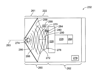
cabinetry). The
fan includes a fan wheel having at least one blade. The fan wheel has a fan
wheel
diameter that is measured from one side of the outer periphery of the fan
wheel to the
opposite side of the outer periphery of the fan wheel. The dimensions of the
air handling
compartment such as height, width, and airway length are determined by
consulting fan
manufacturers data for the type of fan selected.
[0003] During operation, each fan unit produces sounds at frequencies.
In
particular, smaller fan units typically emit sound power at higher audible
frequencies,
whereas larger fan units emit more sound power at lower audible frequencies.
Devices
have been proposed in the past that afford passive sound attenuation such as
with acoustic
1
CA 02735754 2011-03-30
tiles or sound barriers that block or reduce noise transmission. The acoustic
tiles include
a soft surface that deadens reflected sound waves and reverberation of the fan
unit.
[0004] However, passive sound attenuation devices generally affect
noise
transmission in certain directions relative to the direction of air flow.
[0005] A need remains for improved systems and methods to provide
sound
attenuation in air handling systems.
SUMMARY OF THE INVENTION
[0006] In one embodiment, a method for controlling noise produced by
an air
handling system is provided. The method includes collecting sound measurements
from
the air handling system, wherein the sound measurements are defined by
acoustic
parameters. Values for the acoustic parameters are determined based on the
sound
measurements collected. Offset values for the acoustic parameters are
calculated to
define a cancellation signal that at least partially cancels out the sound
measurements
when the cancellation signal is generated. The acoustic parameters may include
a
frequency and amplitude of the sound measurements. Optionally, the
cancellation signal
includes an opposite phase and matching amplitude of the acoustic parameters.
Optionally, response sound measurements are collected at a region of
cancellation and
the cancellation signal is tuned based on the response sound measurements.
[0007] In another embodiment, a system for controlling noise produced
by an
air handling system is provided. The system includes a source microphone to
collect
sound measurements from the air handling system and a processor to define a
cancellation signal that at least partially cancels out the sound
measurements. The system
also includes a speaker to generate the cancellation signal. Optionally, the
speaker
generates the cancellation signal in a direction opposite the sound
measurements.
Optionally, the sound measurements are at least partially canceled out within
a region of
cancellation and the system further includes a response microphone to collect
response
2
CA 02735754 2012-06-01
sound measurements at the region of cancellation. Optionally, the processor
tunes the
cancellation signal based on the response sound measurements.
[0008] In another embodiment, a fan unit is provided. The fan unit
includes a
source microphone to collect sound measurements from the fan unit. A module
defines a
cancellation signal that at least partially cancels out the sound
measurements. A speaker
generates the cancellation signal.
[0008a] In yet another embodiment, there is provided a method, comprising:
positioning a source microphone with respect to a fan unit, wherein the source
microphone is configured to collect sound measurements from the fan unit;
positioning a
speaker with respect to the fan unit, wherein the speaker is configured to
generate a
cancellation signal; and operatively connecting the source microphone and the
speaker to
a module that is configured to define the cancellation signal that at least
partially cancels
out the sound measurements.
[0008b] In yet another embodiment, there is also provided a system configured
to be used in a fan array, the system comprising: a source microphone
configured to
collect sound measurements from a fan unit of the fan array; a module
configured to
define a cancellation signal that at least partially cancels out the sound
measurements;
and a speaker configured to generate the cancellation signal.
BRIEF DESCRIPTION OF THE DRAWINGS
[0009] Figure 1 is a perspective view of an air handler in accordance
with an
embodiment.
[0010] Figure 2 is a perspective view of a stack of the fan arrays in
accordance with an embodiment.
[0011] Figure 3 is a schematic view of a fan unit in accordance with
an
embodiment.
3
CA 02735754 2012-06-01
[0012] Figure 4 is a flowchart of a method for a dynamic feedback loop
in
accordance with an embodiment.
[0013] Figure 5 is a flowchart of a method for providing active sound
attenuation in accordance with an embodiment.
[0014] Figure 6 is a pictorial graphic corresponding to the active
sound
attenuation method of Figure 5.
[0015] Figure 7 is a schematic view of a fan unit in accordance with
an
embodiment.
[0016] Figure 8 is a cross-sectional view of an inlet cone in
accordance with
an embodiment.
3a
CA 02735754 2011-03-30
[0017] Figure 9 is a schematic view of a fan unit in accordance with
an
embodiment.
[0018] Figure 10 is a schematic view of an active-passive sound
attenuator in
accordance with an embodiment.
[0019] Figure 11 is a chart illustrating noise frequencies attenuated
in
accordance with an embodiment.
[0020] Figure 12 is a side view of an inlet cone formed in accordance
with an
embodiment.
[0021] Figure 13 is a side view of a fan unit formed in accordance
with an
embodiment.
[0022] Figure 14 is a front perspective view of a fan unit formed in
accordance with an embodiment.
[0023] Figure 15 is a front perspective view of the fan unit formed in
accordance with an embodiment and having a microphone positioned therein.
DETAILED DESCRIPTION OF THE DRAWINGS
[0024] The foregoing summary, as well as the following detailed
description
of certain embodiments will be better understood when read in conjunction with
the
appended drawings. To the extent that the figures illustrate diagrams of the
functional
blocks of various embodiments, the functional blocks are not necessarily
indicative of the
division between hardware circuitry. Thus, for example, one or more of the
functional
blocks (e.g., processors or memories) may be implemented in a single piece of
hardware
(e.g., a general purpose signal processor or random access memory, hard disk,
or the like)
or multiple pieces of hardware. Similarly, the programs may be stand alone
programs,
may be incorporated as subroutines in an operating system, may be functions in
an
installed software package, and the like. It should be understood that the
various
4
CA 02735754 2012-06-01
embodiments are not limited to the arrangements and instrumentality shown in
the
drawings.
[0025]
As used herein, an element or step recited in the singular and
proceeded with the word "a" or "an" should be understood as not excluding
plural of said
elements or steps, unless such exclusion is explicitly stated. Furthermore,
references to
"one embodiment" are not intended to be interpreted as excluding the existence
of
additional embodiments that also incorporate the recited features. Moreover,
unless
explicitly stated to the contrary, embodiments "comprising" or "having" an
element or a
plurality of elements having a particular property may include additional such
elements
not having that property.
[0026]
Figure 1 illustrates an air processing system 202 that utilizes a fan
array air handling system in accordance with an embodiment of the present
invention.
The system 202 includes an inlet 204 that receives air. A heating section 206
that heats
the air is included and followed by an air handling section 208. A humidifier
section 210
is located downstream of the air handling section 208. The humidifier section
210 adds
and/or removes moisture from the air. Cooling coil sections 212 and 214 are
located
downstream of the humidifier section 210 to cool the air. A filter section 216
is located
downstream of the cooling coil section 214 to filter the air. The sections may
be
reordered or removed. Additional sections may be included.
[0027]
The air handling section 208 includes an inlet plenum 218 and a
discharge plenum 220 that are separated from one another by a bulkhead wall
225 which
forms part of a frame 224. Fan inlet cones 222 are located proximate to the
bulkhead 225
of the frame 224 of the air handling section 208. The fan inlet cones 222 may
be
mounted to the bulkhead wall 225. Alternatively, the frame 224 may support the
fan inlet
cones 222 in a suspended location proximate to, or separated from, the
bulkhead wall
225. Fans 226 are mounted to drive shafts on individual corresponding motors
228. The
motors 228 are mounted on mounting blocks to the frame 224. Each fan 226 and
the
corresponding motor 228 form one of the individual fan units 232 that may be
held in
i
CA 02735754 2012-06-01
separate chambers 230. The chambers 230 are shown vertically stacked upon one
another in a column. Optionally, more or fewer chambers 230 may be provided in
each
column. One or more columns of chambers 230 may be provided adjacent one
another in
a single air handling section 208.
[0028] FIG. 2 illustrates a side perspective view of a column 250
of
chambers 230 and corresponding fan units 232 therein. The frame 224 includes
edge
beams 252 extending horizontally and vertically along the top, bottom and
sides of each
chamber 230. Side panels 254 are provided on opposite sides of at least a
portion of the
fan unit 232. Top and bottom panels 256 and 258 are provided above and below
at least
a portion of the fan units 232. The top and bottom panels 256 may be provided
above
and below each fan unit 232. Alternatively, panels 256 may be provided above
only the
uppermost fan unit 232, and/or only below the lowermost fan unit 232. The
motors are
mounted on brackets 260 which are secured to the edge beams 252. The fans 226
are
open sided plenum fans that draw air inward along the rotational axis of the
fan and
radially discharge the air about the rotational axis in the direction of arrow
262. The air
then flows from the discharge end 264 of each chamber 230 in the direction of
arrows
266.
[0029] The top, bottom and side panels 256, 258 and 254 have a
height
255, a width 257 and a length 253 that are sized to form chambers 230 with
predetermined volume and length. FIG. 2 illustrates the length 253 to
substantially
correspond to a length of the fan 226 and motor 228. Optionally, the length
253 of each
chamber 230 may be longer than the length of the fan 226 and motor 228 such
that the
top, bottom and side panels 256, 258 and 254 extend beyond a downstream end
259 of
the motors 228. For example, the panels 254, 256 and 258 may extend a
distance,
denoted by bracket 253a, beyond the downstream end 259 of the motor 228.
[0030] Figure 3 is a schematic view of an individual fan unit 232.
The fan
unit includes a fan 226 that is driven by a motor 228. An inlet cone 222 is
coupled
upstream of the fan 226 and includes a center axis 263. The fan unit 232
includes an
upstream region 260 and a downstream region 262. A motor controller 264 is
positioned
6
CA 02735754 2011-03-30
adjacent the motor 228. Optionally, the motor controller 264 may be located
adjacent
one of top, bottom and side panels 256, 258 and 254, as shown in Figure 2,
and/or remote
from the fan unit 232.
[0031] During operation, the motor 228 rotates the fan 226 to draw air
through the inlet cone 222 from an inlet plenum 261 toward the downstream
region 262.
It should be noted that with respect to airflow, "upstream" is defined as
traveling from the
fan 226 to the inlet cone 222 and "downstream" is defined as traveling from
the inlet
cone 222 to the fan 226. The motor controller 264 may adjust a speed of the
fan 226 to
reduce or increase an amount of air flow through the fan unit 232. Noise may
travel both
upstream 260 and downstream 262 from the fan unit 232. The noise may include
fan
noise generated by vibrations or friction in the fan 226 or motor 228 among
other things.
The noise may also include environmental noise generated outside the fan unit
232. Both
the fan noise and the environmental noise have acoustic parameters including
frequency,
wavelength, period, amplitude, intensity, speed, and direction. The noise
travels in a
noise vector 266.
[0032] The fan unit 232 includes active sound attenuation to reduce
the fan
noise within a region of active cancellation 268. The region of active
cancellation 268 is
in the throat 269 of the inlet cone 222. Optionally, the region of active
cancellation 268
may be upstream from the inlet cone 222. In the exemplary embodiment, the
region of
active cancellation 268 is located in the upstream region 260. Optionally, the
region of
active cancellation 268 may be located in the downstream region 262. The
active sound
attenuation may reduce any one of the acoustic parameters to approximately
zero using
destructive interference. Destructive interference is achieved by the
superposition of a
sound waveform onto a original sound waveform to eliminate the original sound
waveform by reducing or eliminating one of the acoustic parameters of the
original
waveform. In an exemplary embodiment, the amplitude of the noise vector 266 is
reduced or substantially eliminated. Optionally, any of the acoustic
parameters of the
noise vector 266 may be eliminated.
7
CA 02735754 2011-03-30
[0033] Active sound attenuation is enabled by a source microphone 270,
a
response microphone 272, a speaker 274, and an attenuation module 276. The
source
microphone 270 is positioned within the inlet cone 222. The source microphone
270 is
configured to detect the noise vector 266. The step of detecting the noise
vector 266
includes obtaining sound measurements having acoustic parameters. For example,
a
sound pressure of the noise vector 266 may be obtained to determine the
acoustic
parameters. The source microphone 270 may be positioned at the juncture 278 of
the
inlet cone 222 and the fan 226. Optionally, the source microphone 270 may be
positioned along any portion of inlet cone 222 or upstream from the inlet cone
222. In
the exemplary embodiment, the source microphone 270 is located flush with an
inner
surface 280 of the inlet cone 222 to reduce disturbances in air flow through
the inlet cone
222. Optionally, the source microphone 270 may extend toward the center axis
263 on a
boom or bracket.
[0034] In the exemplary embodiment, the source microphone 270 includes
a
pair of microphones configured to bias against environmental noise.
Optionally, the
source microphone may only include one microphone. The pair of microphones
includes
a downstream microphone 282 and an upstream microphone 284. Optionally, source
microphone 270 may include a plurality of microphones configured to bias
against
environmental noise. In one embodiment, the upstream microphone 284 may be
positioned approximately 50 mm from the downstream microphone 282. Optionally,
microphones 282 and 284 may have any suitable spacing. Further, in the
exemplary
embodiment, microphone 282 is positioned in approximately the same
circumferential
location as microphone 284. Optionally, microphones 282 and 284 may be
positioned
within different circumferential locations of the inlet cone 222.
[0035] Microphones 282 and 284 bias against environmental noise so
that
only fan noise is attenuated. Environmental noise is detected by the upstream
microphone 284 and the downstream microphone 282 at substantially the same
time.
However, a time delay exists between downstream microphone 282 sensing the fan
noise
and upstream microphone 284 sensing the fan noise. Accordingly, the fan noise
can be
8
CA 02735754 2012-06-01
distinguished from the environmental noise and the environmental noise is
removable
from the noise vector 266.
[0036] The speaker 274 is positioned upstream from the inlet cone 222.
The
speaker 274 may be fabricated from a perforated foam or metal. For example,
the
speaker 274 may be fabricated from acoustically transparent foam. In an
embodiment,
the speaker 274 has an aerodynamic shape that has a limited effect on the fan
performance. For example, the speaker 274 may be domed-shaped. In the
exemplary
embodiment, the speaker 274 is mounted on a tripod or similar mount 286.
Optionally,
the speaker 274 may be coupled to one of panels 254, 256 and 258 or to frame
224.
Additionally, the speaker 274 may be positioned upstream of the fan unit and
configured
to attenuate noise within the entire fan unit. The speaker 274 is aligned with
the center
axis 263 of the inlet cone 222. Optionally, the speaker 274 may be offset from
the center
axis 263. The speaker 274 may also be angled toward the center axis 263. The
speaker
274 transmits an attenuation vector 288 downstream and opposite the noise
vector 266.
The attenuation vector 288 is an inverted noise vector 266 having an opposite
phase and
matching amplitude of the noise vector 266. The attenuation vector 288
destructively
interferes with the noise vector 266 to generate an attenuated noise vector
290 having an
amplitude of approximately zero. Optionally, the attenuating vector 288
reduces any of
the noise vector acoustic parameters so that the attenuated noise vector 290
is inaudible.
[0037] The response microphone 272 is positioned upstream of the
source
microphone 270 and within the region of active cancellation 268. The response
microphone 272 is located flush along the inner surface 280 of the inlet cone
222.
Optionally, the response microphone 272 may extend toward the center axis 263
on a
boom or bracket. Additionally, the response microphone 272 may be positioned
in the
inlet plenum 261 and/or upstream of the fan unit 232. The response microphone
272 is
configured to detect the attenuated noise vector 266. Detecting the attenuated
noise
vector 290 includes obtaining sound measurements having acoustic parameters.
For
example, a sound pressure of the attenuated noise vector 290 may be obtained
to
determine the acoustic parameters. As described in more detail below, the
attenuated
9
CA 02735754 2012-06-01
noise vector 290 is compared to the noise vector 266 to determine whether the
noise
vector 266 has been reduced or eliminated.
[0038] Typically, the noise vector 266 remains dynamic throughout the
operation of the fan unit 232. Accordingly, the attenuation vector 288 must be
modified
to adapt to changes in the noise vector 266. The attenuating module 276 is
positioned
within the fan unit 232 to modify the attenuation vector 288. Optionally, the
attenuating
module 276 may be positioned within the air processing system 200 or may be
remote
therefrom. The attenuating module 276 may be programmed internally or
configured to
operate software stored on a computer readable medium.
[0039] Figure 4 is a block diagram of the attenuating module 276
electronically coupled to the source microphone 270 and the response
microphone 272.
The attenuating module 276 includes an amplifier 302 and an automatic gain
control 304
to modify the noise vector 266 detected by the source microphone 270.
Likewise, an
amplifier 306 and an automatic gain control 308 modify the attenuated noise
vector 290
detected by the response microphone 272. A CODEC 310 digitally encodes the
noise
vector 266 and the attenuated noise vector 290. A digital signal processor 312
obtains the
acoustic parameters of each vector 266 and 290. The vectors are compared
utilizing an
adaptive signal processing algorithm 314 to determine whether the noise vector
266 has
been attenuated. Based on the comparison, the attenuation module 276 modifies
the
attenuation vector 288, which is digitally decoded by the CODEC 310,
transmitted to an
amplifier 316, and transmitted by the speaker 274.
[0040] Figure 5 illustrates a method 400 for active attenuation of the
noise
vector 266. Figure 6 is a pictorial graphic corresponding to active
attenuation. During
operation of the fan unit 232 the noise vector 266 travels from the fan unit
232. At 402,
the source microphone 270 detects the noise vector 266. Detecting the noise
vector 266
may include detecting a sound pressure, intensity and/or frequency of the
noise vector
266. The noise vector is detected as a waveform 404, as shown in Figure 6.
CA 02735754 2012-06-01
[0041] At 406, environmental noise is removed from the noise vector
266.
The noise vector 266 is detected by both the downstream microphone 282 and the
upstream microphone 284. The downstream microphone 282 is positioned closer to
the
fan 226 along the incoming air flow path than the upstream microphone 284.
Thus, the
downstream microphone 282 acquires the sound measurements from the fan unit
232 a
predetermined time period before the same sound measurements are acquired by
the
upstream microphone 284. The downstream and upstream microphones 282 and 284
sense a common sound at slightly different points in time. The time period
between
when the downstream and upstream microphones 282 and 284 sense the common
sound
is determined by the spacing or distance between the downstream and upstream
microphones 282 and 284 along the air flow path. A delay corresponding to the
time
period may be introduced into the signal from the downstream microphone 282.
At 406,
a difference is obtained between the signals from downstream and upstream
microphones
282 and 284. By adjusting the delay, the source microphone 270 is tuned to be
sensitive
to sound originating from a particular direction.
[0042] As such, environmental noise, not generated by the fan unit
232, is
filtered from the noise vector at 266 by setting a time delay between the
downstream
microphone 282 and the upstream microphone 284. Sound pressures received by
the
upstream microphone 284, not first received by the downstream microphone 282,
are
indicative of environmental noise that is not generated by the fan 226.
Accordingly, the
method 400 filters out non-fan unit noises acquired by the source microphone
270.
Optionally, if the noise vector 266 is not within an audible range, the signal
may be
ignored by the attenuating module 276. Once the signals from the microphones
282 and
284 are combined (e.g., subtracted from one another), a filtered fan unit
noise signal is
produced.
[0043] At 410, the filtered fan unit noise is analyzed to obtain
values for the
acoustic parameters 411 of the sound measurements. The acoustic parameters 411
may
be calculated using an algorithm, determined using a look-up table, and/or may
be pre-
determined and stored in the attenuation module 276. The acoustic parameters
of interest
11
CA 02735754 2011-03-30
may include the frequency, wavelength, period, amplitude, intensity, speed,
and/or
direction of the filtered fan unit noise. At 412, an attenuation signal 414 is
generated.
The attenuation signal 414 may be generated by inverting the waveform of the
filtered
fan unit noise 408. As shown in Figure 6, the attenuation signal 414 has an
equal
amplitude and a waveform that is 180 degrees out of phase with the filtered
fan unit noise
waveform 408.
[0044] At 416, the attenuation signal 414 is transmitted to the
speaker 274 to
generate the attenuation vector 288. The attenuation vector 288 is transmitted
downstream in a direction opposite the noise vector 266. The attenuation
vector 288 has
a matching amplitude and opposite phase in relation to the noise vector 266.
Thus, the
attenuation vector 288 destructively interferes 417 with the noise vector 266
by reducing
the amplitude of the noise vector 266 to approximately zero, as shown at 418
of Figure 6.
It should be noted that the amplitude may be reduced to any range that is
inaudible.
Optionally, the attenuation vector 288 may reduce or eliminate any other
acoustic
parameter of the noise vector 266. Further, in the exemplary embodiment, the
attenuation
vector 288 is timed so that the noise vector 266 is attenuated within the
region of active
cancellation 268, thereby also eliminating the noise vector 266 upstream of
the region of
active cancellation 268.
[0045] At 420, the response microphone 272 monitors the attenuation of
the
noise vector 266. In the exemplary embodiment, the response microphone 272
monitors
the attenuation in real-time. As used herein real-time refers to actively
monitoring the
attenuation as the attenuation vector 288 is transmitted from the speaker 274.
[0046] At 422, the response microphone 272 detects the attenuated
noise
vector 290. At 424, the attenuated noise vector 290 is compared to the noise
vector 266
to provide a dynamic feedback loop that adjusts and tunes the attenuation
vector 288.
[0047] Figure 7 illustrates a fan unit 500 in accordance with an
embodiment.
The fan unit 500 includes an inlet cone 502, a fan assembly 504, and a motor
506. The
inlet cone 502 is positioned upstream from the fan assembly 504. The inlet
cone 502
12
CA 02735754 2011-03-30
includes a throat 508 positioned directly upstream from the fan assembly 504.
It should
be noted that with respect to airflow "upstream" is defined as traveling from
the fan 504
to the inlet cone 502 and "downstream" is defined as traveling from the inlet
cone 502 to
the fan 504. A source microphone 510 is positioned within the throat 508 of
the inlet
cone 502. The source microphone 510 may include a pair of microphones.
Optionally,
the source microphone 510 may include only one microphone. A pair of speakers
512 is
positioned upstream from the source microphone 510. Optionally, there may be
additional speakers 512. The speakers 512 are positioned within the inlet cone
502. The
speakers 512 are aerodynamically configured to limit an effect on the fan
performance.
In an embodiment, the speakers 512 are positioned within the same cross-
sectional plane.
Optionally, the speakers 512 may be offset from one another. A response
microphone
514 is positioned upstream of the speakers 512. The response microphone 514 is
positioned within the inlet cone 502. Optionally, the response microphone 514
may be
positioned upstream of the fan unit 500.
[0048] Noise generated by the fan 504 travels upstream. The noise is
detected
by the source microphone 510. In response to the detected noise, the speakers
512
transmit attenuating sound fields configured to destructively interfere with
the noise. The
result of the destructive interference is detected by the response microphone
514 to
provide a feedback loop to the speakers 512.
[0049] Figure 8 illustrates a cross-section of an inlet cone 550 in
accordance
with an embodiment. The inlet cone 550 includes a source microphone 552 and
speakers
554. The source microphone 552 and the speakers 554 are each positioned 90
degrees
from each other. Optionally, the source microphone 552 and the speakers 554
may be
positioned along any portion of the inlet cone circumference. Additionally,
the inlet cone
550 may include a pair of source microphones 552 and/or any number of speakers
554.
In the example embodiment, the source microphone 552 and the speakers 554 are
each
positioned in the same cross-sectional plane of the inlet cone 550.
Optionally, the source
microphone 552 and the speakers 554 may be offset from one another.
13
CA 02735754 2011-03-30
[0050] Noise travels through the inlet cone 550. The noise is detected
by the
source microphone 552. The speakers then generate an attenuation sound field
to
destructively interfere with the noise.
[0051] Figure 9 illustrates a fan unit 600 in accordance with an
embodiment.
The fan unit 600 includes an inlet cone 602, a fan assembly 604, and a motor
606. The
inlet cone 602 is positioned upstream from the fan assembly 604. An inlet
plenum 608 is
positioned upstream from the inlet cone 602. It should be noted that with
respect to
airflow "upstream" is defined as traveling from the fan 604 to the inlet cone
602 and
"downstream" is defined as traveling from the inlet cone 602 to the fan 604. A
source
microphone 610 is positioned within the inlet cone 602. The source microphone
610 may
include a pair of microphones. Optionally, the source microphone 610 may
include only
one microphone. A pair of speakers 612 is positioned within the inlet plenum
608.
Optionally, fan unit 600 may include any number of speakers 612. The speakers
612 are
aerodynamically configured to limit an effect on the fan performance. The
speakers 612
are coupled to a strut 614 that extends through the inlet plenum 608 and
across an
opening of the inlet cone 602. The strut 614 is angled to angle the speakers
612 with
respect to one another. Optionally, the strut may be arced and configured to
retain any
number of speakers 612.
[0052] Noise generated by the fan 604 travels upstream. The noise is
detected
by the source microphone 610. In response to the detected noise, the speakers
612
transmit attenuating sound fields configured to destructively interfere with
the noise.
[0053] Figure 10 illustrates an active-passive sound attenuation system
650 in
accordance with an embodiment. The system 650 is positioned within an air
plenum 652
having airflow 654 therethrough. The plenum 652 includes a pair of walls 656.
The
walls 656 are arranged in parallel. Optionally, the walls 656 may be angled
with respect
to each other to provide a plenum width that converges and/or diverges. A
baffle 658 is
positioned within the plenum 652. Air channels 660, 662 extend between the
baffle 658
and the walls 656. In the exemplary embodiment, air channels 660, 662 have
equivalent
14
CA 02735754 2012-06-01
widths 664. Optionally, the baffle 658 may be positioned so that the widths
664 of
channels 660 and 662 differ. The baffle 658 is also positioned in parallel
with the walls
656. Optionally, the baffle 658 may be angled with respect to the walls 656.
Additionally, the baffle 658 may be rounded and/or have any non-linear shape.
The
baffles 658 include a sound attenuating material. The sound attenuating
material has a
porous medium configured to absorb sound. For example, the sound attenuating
material
may include a fiberglass core.
[0054] A source microphone 668 is positioned within each wall 656.
Optionally, the source microphone 668 may be positioned in only one wall 656.
Alternatively, the source microphone 668 may be positioned within the baffle
658. The
source microphone 668 may be positioned upstream from the baffle 658 or,
optionally,
downstream from the baffle 658. Speakers 670 are positioned within the walls
656.
Alternatively, only one speaker 670 may be positioned within the wall. The
speaker 670
may also be positioned within the baffle 658. The speaker 670 is positioned
downstream
from the source microphone 668. In one embodiment, the speaker 670 may be
positioned
downstream from the baffle 658 and configured to direct attenuating noise in a
counter-
direction of the airflow 654.
[0055] Noise generated within the plenum 652 travels upstream with
airflow
654. The baffle 658 provides passive sound attenuation. Additionally, the
source
microphone 668 detects the noise to provide active sound attenuation. The
speakers 670
transmit a sound attenuating noise which destructively interferes with the
noise
propagating through the plenum 652.
[0056] Figure 11 is a chart 700 illustrating noise frequencies
attenuated in
accordance with an embodiment. The chart 700 includes sound pressure (Lp) on
the y-
axis 702 and frequency on the x-axis 704. Seven octave bands 706 are charted.
Each
octave band 706 includes a peak frequency. The peak frequencies illustrated
are 31 Hz,
63 Hz, 125 Hz, 250 Hz, 500 Hz, 1000 Hz, and 2000 Hz. The dominant noise
components
generated by a fan array generally have frequencies in common with these peak
CA 02735754 2011-03-30
frequencies. Accordingly, the embodiments described herein are generally
configured to
attenuate noise propagating at the peak frequencies of octave bands 706. For
example, a
dominant frequency component of the noise may include the blade pass frequency
of the
fan. The blade pass frequency is determined using the following:
BPF = (RPM * # of blades) /60
wherein BPF is the blade pass frequency, RPM is the rotations per minute of
the fan, and
# of blades is the number of fan blades. Typically, the blade pass frequency
is
approximately 250 Hz. This frequency travels at approximately 70-90 dB.
Accordingly,
an object of the invention is to attenuate noises within the range of 250 Hz.
Although the
embodiments are described with respect to attenuating noises having a peak
frequency, it
should be noted that the embodiments described herein are likewise capable of
attenuating any frequency.
[0057] Figure 12 is a side view of an inlet cone 800 formed in
accordance
with an embodiment. The inlet cone 800 includes an inlet 802 and an outlet
804. In an
exemplary embodiment, the inlet 802 and the outlet 804 have a parabolic shape.
The
inlet 802 has a width 806 that is greater than a width 808 of the outlet 804.
The outlet
804 is configured to be positioned adjacent a fan wheel of a fan unit. In one
embodiment,
the outlet is coupled to the fan wheel. An intermediate portion 810 extends
between the
inlet 802 and the outlet 804. In the illustrated embodiment, the intermediate
portion 810
is cylindrical in shape. In alternative embodiments, the intermediate portion
810 may
have any suitable shape.
[0058] The intermediate portion 810 includes a plurality of apertures
812
formed therethrough. The apertures 812 are formed in an array around the
intermediate
portion. The apertures 812 are configured to retain speakers 814 (shown in
Figure 13)
therein. The intermediate portion 810 may include any suitable number of
apertures 812
for retaining any suitable number of speakers 814. The apertures 812 may be
uniformly
spaced about the intermediate portion 810. In one embodiment, the inlet cone
800 may
includes apertures 812 in the inlet 802 and/or outlet 804.
16
CA 02735754 2011-03-30
[0059] Figure 13 is a side view of a fan unit 820 formed in
accordance with
an embodiment. Figure 14 is a front perspective view of a fan unit 820. The
fan unit 820
includes the inlet cone 800. The inlet cone 800 is joined to the fan wheel 822
of the fan
unit 820. Speakers 814 are positioned in the apertures 812 (shown in Figure
12) of the
inlet cone 800. The speakers 814 are arranged in an array around the
circumference of
the inlet cone 800. The speakers 814 are arranged in an array around the
circumference
of the intermediate portion 810 of the inlet cone 800.
[0060] Figure 15 is a front perspective view of the fan unit 820
having a
microphone 826 positioned therein. The fan wheel 822 includes a hub 824 having
fan
blades 828 extending therefrom. In an exemplary embodiment, a microphone
assembly
832 is positioned with the hub 824 of the fan wheel 822. The microphone 826 is
positioned within the microphone assembly 832. The illustrated embodiment
includes
four microphones 826 positioned in an array within the microphone assembly
832. In
alternative embodiments, the fan unit 820 may include any number of
microphones 826
arranged in any manner. For example, the fan unit 820 may include a single
microphone
. 826 centered in the hub 824.
[0061] The microphone assembly 832 includes a cover 830 is
positioned over
the microphones 826. The cover 830 may be inserted into the hub 824 of the fan
wheel
822. The cover 830 may abut the hub 824 of the fan wheel 822 in alternative
embodiments. The cover 830 may be formed from a perforated material to allow
sound
waves to pass therethrough. The cover 830 may be formed from foam or the like
in some
embodiments. The cover 830 limits air flow to the microphones 826 while
allowing
sound waves to propagate to the microphones 826. The microphones 826 are
configured
to collect sound measurements from the fan unit 820. In response to the sound
measurements, the array of speakers 814 generates a cancellation signal.
[0062] In the illustrated embodiment, the microphone assembly 832 is
supported by a boom 834. The boom 834 retains the microphone assembly 832
within
the hub 824 of the fan wheel 822. The boom 834 enables the fan wheel 822 to
rotate with
17
CA 02735754 2012-06-01
disturbing a position of the microphone assembly 832. The boom 834 is joined
to a
support beam 836 that retains a position of the boom 834 and the microphone
assembly
832.
[0063] The
embodiments described herein are described with respect to an air
handling system. It should be noted that the embodiments described may be used
within
the air handling unit and/or in the inlet or discharge plenum of the air
handling system.
The embodiments may also be used upstream and/or downstream of the fan array
within
the air handling unit. Optionally, the described embodiments may be used in a
clean
room environment. The embodiments may be positioned in the discharged plenum
and/or the return chase of the clean room. Optionally, the embodiments may be
used in
residential HVAC systems. The embodiments may be used in the ducts of an HVAC
system. Optionally, the embodiments may be used with precision air control
systems,
DX and chilled-water air handlers, data center cooling systems, process
cooling systems,
humidification systems, and factory engineered unit controls.
Optionally, the
embodiments may be used with commercial and/or residential ventilation
products. The
embodiments may be used in the hood and/or inlet of the ventilation product.
Optionally,
the embodiments may be positioned downstream of the inlet in a duct and/or at
a
discharge vent.
[0064] The
various embodiments described herein enable active monitoring of
noise generated by a fan unit. By actively monitoring the noise, an
attenuation signal is
dynamically generated to cancel the noise. The attenuation signal is generated
by
inverting a noise signal acquired within the fan unit. Accordingly,
attenuation is
maximized by matching the amplitude of the noise signal. Additionally, the
attenuation
signal is configured to destructively interfere with the noise within a range
defined inside
the fan unit cone. As a result, the noise generated by the fan is attenuated
prior to exiting
the fan unit. The response microphone enables continual feedback of the
attenuation,
thereby promoting the dynamic changes of the system.
18
CA 02735754 2011-03-30
[0065] The various embodiments and/or components, for
example, the
modules, or components and controllers therein, also may be implemented as
part of one
or more computers or processors. The computer or processor may include a
computing
device, an input device, a display unit and an interface, for example, for
accessing the
Internet. The computer or processor may include a microprocessor. The
microprocessor
may be connected to a communication bus. The computer or processor may also
include
a memory. The memory may include Random Access Memory (RAM) and Read Only
Memory (ROM). The computer or processor further may include a storage device,
which
may be a hard disk drive or a removable storage drive such as a floppy disk
drive, optical
disk drive, and the like. The storage device may also be other similar means
for loading
computer programs or other instructions into the computer or processor.
[0066] As used herein, the term "computer" or "module"
may include any
processor-based or microprocessor-based system including systems using
microcontrollers, reduced instruction set computers (RISC), ASICs, logic
circuits, and
any other circuit or processor capable of executing the functions described
herein. The
above examples are exemplary only, and are thus not intended to limit in any
way the
definition and/or meaning of the term "computer".
[0067] The computer or processor executes a set of
instructions that are stored
in one or more storage elements, in order to process input data. The storage
elements
may also store data or other information as desired or needed. The storage
element may
be in the form of an information source or a physical memory element within a
processing machine.
[0068] The set of instructions may include various
commands that instruct the
computer or processor as a processing machine to perform specific operations
such as the
methods and processes of the various embodiments of the invention. The set of
instructions may be in the form of a software program. The software may be in
various
forms such as system software or application software. Further, the software
may be in
the form of a collection of separate programs or modules, a program module
within a
19
4
CA 02735754 2011-03-30
larger program or a portion of a program module. The software also may include
modular programming in the form of object-oriented programming. The processing
of
input data by the processing machine may be in response to operator commands,
or in
response to results of previous processing, or in response to a request made
by another
processing machine.
[0069] As used herein, the terms "software" and "firmware" are
interchangeable, and include any computer program stored in memory for
execution by a
computer, including RAM memory, ROM memory, EPROM memory, EEPROM
memory, and non-volatile RAM (NVRAM) memory. The above memory types are
exemplary only, and are thus not limiting as to the types of memory usable for
storage of
a computer program.
[0070] It is
to be understood that the above description is intended to be
illustrative, and not restrictive. For example, the above-described
embodiments (and/or
aspects thereof) may be used in combination with each other. In addition, many
modifications may be made to adapt a particular situation or material to the
teachings of
the various embodiments of the invention without departing from their scope.
While the
dimensions and types of materials described herein are intended to define the
parameters
of the various embodiments of the invention, the embodiments are by no means
limiting
and are exemplary embodiments. Many other embodiments will be apparent to
those of
skill in the art upon reviewing the above description. The scope of the
various
embodiments of the invention should, therefore, be determined with reference
to the
appended claims, along with the full scope of equivalents to which such claims
are
entitled. In the appended claims, the terms "including" and "in which" are
used as the
plain-English equivalents of the respective terms "comprising" and "wherein."
Moreover, in the following claims, the terms "first," "second," and "third,"
etc. are used
merely as labels, and are not intended to impose numerical requirements on
their objects.
Further, the limitations of the following claims are not written in means-plus-
function
format and are not intended to be interpreted based on 35 U.S.C. 112, sixth
paragraph,
CA 02735754 2011-03-30
unless and until such claim limitations expressly use the phrase "means for"
followed by
a statement of function void of further structure.
[0071] This
written description uses examples to disclose the various
embodiments of the invention, including the best mode, and also to enable any
person
skilled in the art to practice the various embodiments of the invention,
including making
and using any devices or systems and performing any incorporated methods. The
patentable scope of the various embodiments of the invention is defined by the
claims,
and may include other examples that occur to those skilled in the art. Such
other
examples are intended to be within the scope of the claims if the examples
have structural
elements that do not differ from the literal language of the claims, or if the
examples
include equivalent structural elements with insubstantial differences from the
literal
languages of the claims.
21