Note: Descriptions are shown in the official language in which they were submitted.
CA 02735920 2011-03-03
WO 2010/034628 PCT/EP2009/061798
- 1 -
PROCESS FOR REMOVING GASEOUS CONTAMINANTS FROM A FEED GAS
STREAM COMPRISING METHANE AND GASEOUS CONTAMINANTS
The present invention concerns a process for the
removal of gaseous contaminants from a feed gas stream
which comprises methane and gaseous contaminants, in
particular the removal of gaseous contaminants such as
carbon dioxide and hydrogen sulphide from a natural gas.
Methane comprising gas streams produced from
subsurface reservoirs, especially natural gas, associated
gas and coal bed methane, usually contain contaminants as
carbon dioxide, hydrogen sulphide, carbon oxysulphide,
mercaptans, sulphides and aromatic sulphur containing
compounds in varying amounts. For most of the applications
of these gas streams, the contaminants need to be removed,
either partly or almost completely, depending on the
specific contaminant and the use. Often, the sulphur
compounds need to be removed into the ppm level, carbon
dioxide sometimes into the ppm level, e.g. LNG
applications, or down to 2 or 3 vol. percent, e.g. for use
as heating gas. Higher hydrocarbons may be present, which,
depending on the use, may be recovered.
Processes for the removal of carbon dioxide and
sulphur compounds are know in the art. These processes
include absorption processes using e.g. aqueous amine
solutions or adsorption processes using e.g. molecular
sieves. These processes are especially suitable for the
removal of contaminants, especially carbon dioxide and
hydrogen sulphide, that are present in relatively low
amounts, e.g. up till several vol%.
In WO 2006/087332, a method has been described for
removing contaminating gaseous components, such as carbon
CA 02735920 2011-03-03
WO 2010/034628 - 2 - PCT/EP2009/061798
dioxide and hydrogen sulphide, from a natural gas stream.
In this method a contaminated natural gas stream is cooled
in a first expander to obtain an expanded gas stream having
a temperature and pressure at which the dewpointing
conditions of the phases containing a preponderance of
contaminating components, such a carbon dioxide and/or
hydrogen sulphide are achieved. The expanded gas stream is
then supplied to a first segmented centrifugal separator to
establish the separation of a contaminants-enriched liquid
phase and a contaminants-depleted gaseous phase. The
contaminants-depleted gaseous phase is then passed via a
recompressor, an interstage cooler, and a second expander
into a second centrifugal separator. The interstage cooler
which is utilising air, water and/or an internal cold
process stream, e.g. cold gas and/or liquid obtained form
step 3), and the second expander are used to cool the
contaminants-depleted gaseous phase to such an extent that
again a contaminants-enriched liquid phase and a further
contaminants-depleted gaseous phase are obtained which are
subsequently separated from each other by means of the
second centrifugal separator. In such a method energy
recovered from the first expansion step is used in the
compression step.
A disadvantage of this known method is that there is
still room for improving the removal of gaseous
contaminants from the feed gas stream, ensuring that levels
can be reached that are specified for pipeline transport of
the feed gas stream or the production of liquefied natural
gas. A further disadvantage of such a method is that there
is still room to improve the hydrocarbon efficiency of such
a method, which hydrocarbon efficiency is a measure of the
fuel consumption and the hydrocarbon loss into the liquid
phase contaminant streams during the process.
CA 02735920 2011-03-03
WO 2010/034628 - 3 - PCT/EP2009/061798
It has now been found that in an integrated process
for removing gaseous contaminants improved levels of
gaseous contaminants and an improved hydrocarbon efficiency
can be obtained when after a gas/liquid separation the
contaminants-depleted gaseous phase is subjected to a
distillation treatment.
Thus, the present invention concerns a process for
removing gaseous contaminants from a feed gas stream which
comprises methane and gaseous contaminants, which process
comprises:
1) providing the feed gas stream;
2) cooling the feed gas stream to a temperature at which
liquid phase contaminant is formed as well as a methane
enriched gaseous phase;
3) separating the two phases obtained in step 2) by means
of a gas/liquid separator; and
4) subjecting the methane enriched gaseous phase obtained
in step 3) to a distillation treatment in a distillation
section thereby obtaining a bottom stream rich in liquid
phase contaminant and lean in methane, and a top stream
rich in methane and and lean in gaseous contaminant.
Suitably, the feed gas stream is a natural gas stream
in which the gaseous contaminants are carbon dioxide and/or
hydrogen sulphide. The natural gas stream suitably
comprises between 0.1 and 60 vol% of hydrogen sulphide,
preferably between 20 and 40 vol% of hydrogen sulphide. The
natural gas stream suitably comprises between 1 and 90 vol%
of carbon dioxide, preferably between 5 and 80 vol% of
carbon dioxide.
The feed gas stream to be used in accordance with the
present invention comprises between 20 and 80 vol% of
methane.
Suitably, the feed gas stream in step 1) has a
temperature between -20 and 150 C, preferably between -10
CA 02735920 2011-03-03
WO 2010/034628 - 4 - PCT/EP2009/061798
and 70 C, and a pressure between 10 and 150 bara,
preferably between 80 and 120 bara.
The raw feed gas stream may be pre-treated to
partially or completely remove water and optionally some
heavy hydrocarbons. This can for instance be done by
means of a pre-cooling cycle, against an external cooling
loop or a cold internal process stream. Water may also be
removed by means of pre-treatment with molecular sieves,
e.g. zeolites, or silica gel or alumina oxide or other
drying agents such as glycol, MEG, DEG or TEG, or glycerol.
The amount of water in the gas feed stream is suitably less
than 1 vol%, preferably less than 0.1 vol%, more preferably
less than 0.0001 vol%.
The cooling in step 2) of the feed gas stream may be
done by methods known in the art. For instance, cooling may
be done against an internal or external cooling fluid. In
the case that the pressure of the feed gas is sufficiently
high, cooling may be obtained by expansion of the feed gas
stream.
Combinations may also be possible. A suitable method to
cool the feed gas stream is by nearly isentropic
expansion, especially by means of an expander, preferably a
turbo expander or laval nozzle. Another suitable method is
to cool the feed gas stream by isenthalpic expansion,
preferably isenthalpic expansion over an orifice or a
valve, especially over a Joule-Thomson valve.
Preferably, the expansion is done using at least two
expansion devices and the operating parameters of the
expansion devices are chosen such that the liquefied acidic
contaminants have a certain droplet size distribution. In
this way, the droplet size distribution can be controlled.
In a preferred embodiment the feed gas stream is pre-
cooled before expansion. This may be done against an
external cooling loop or against a cold internal process
CA 02735920 2011-03-03
WO 2010/034628 - 5 - PCT/EP2009/061798
stream, e.g. liquid acidic contaminant. Preferably the gas
stream is pre-cooled before expansion to a temperature
between 15 and -35 C, preferably between 10 and -20 C.
Especially when the feed gas stream has been compressed,
the temperature of the feed gas stream may be between 100
and 150 C. In that case air or water cooling may be used to
decrease the temperature first, optionally followed by
further cooling.
Another suitable cooling method is heat exchange
against a cold fluidum, especially an external refrigerant,
e.g. a propane cycle, an ethane/propane cascade or a mixed
refrigerant cycle, optionally in combination with an
internal process loop, suitably a contaminants stream
(liquid or slurry), a cold methane enriched stream or
washing fluid.
Suitably the feed gas stream is cooled in step 2) to a
temperature between -30 and -80 C, preferably between -40
and -65 C. At these temperatures liquid phase contaminant
will be formed.
In the present invention both liquid phase contaminant
and gaseous contaminant will comprise carbon dioxide and/or
hydrogen sulphide.
In step 4), the bottom temperature of the distillation
device is suitably between 0 and 30 C, and preferably
between 5 and 20 C, whereas the top temperature of the
distillation device is between -20 and -90 C, preferably
between -30 and -70 C.
In accordance with the present invention the
distillation device can suitable be a distillation column
or distillation vessel known in the art.
Suitably, the top stream in step 4) comprises between
1 and 75 mol% of the gaseous contaminants present in the
feed gas stream. Preferably, the top stream in step 4)
CA 02735920 2011-03-03
WO 2010/034628 _ 6 _ PCT/EP2009/061798
comprises between 2 and 50 mol% of the gaseous contaminants
present in the feed gas stream.
Hence, it will be clear that with the relatively
simple process according to the invention very low levels
of gaseous contaminants can be established in the methane
enriched gaseous phase, ensuring that levels can be reached
that are specified for pipeline transport of the feed gas
stream or the production of liquefied natural gas.
In accordance with the present invention the methane
enriched gaseous phase obtained in step 3) can suitably be
cooled in a cooling step to a temperature at which liquid
phase contaminant is formed as well as a methane enriched
gaseous phase, and the methane enriched gaseous phase so
obtained is subjected to the distillation treatment in
step 4).
The cooling between steps 3) and 4) can, e.g. be
carried out by means of an internal process stream, e.g. a
stream of liquid phase contaminant which is separated from
the methane enriched gaseous phase in step 3).
In accordance with the present invention the cooling
of the methane enriched gaseous phase between steps 3) and
4) can suitably at least partly be done by means of an
external refrigerant.
Preferably, the external refrigerant to be used has a
higher molecular weight than the methane enriched gaseous
phase to be cooled. Suitable examples of such cooling
medium include ethane, propane and butane. Preferably, the
cooling medium comprises ethane and/or propane.
More preferably, the external refrigerant to be used
comprises a propane cycle, an ethane/propane mixed
refrigerant or an ethane/propane cascade. Such an
ethane/propane cascade is described in more detail
hereinbelow.
CA 02735920 2011-03-03
WO 2010/034628 - 7 - PCT/EP2009/061798
In a preferred embodiment of the present invention
the methane enriched gaseous phase obtained in step 3) is
recompressed in one or more compression steps before the
methane enriched gaseous phase is cooled by means of the
internal and/or external refrigerant.
Suitably, the recompressed methane enriched gaseous
phase obtained in the one or more compression steps is
cooled in a cooling step to a temperature at which liquid
phase contaminant is formed as well as a methane enriched
gaseous phase, whereafter the methane enriched gaseous
phase so obtained is subjected to the distillation
treatment in step 4).
The cooling of the methane enriched gaseous phase
between steps 3) and 4) can suitably be partly done by
means of an external refrigerant and partly by means of an
internal process stream such as a stream of liquid phase
contaminant which is separated from the methane enriched
gaseous phase in step 3).
The cooling by means of the external refrigerant may
be carried out in such a way that a stream is obtained
comprising liquid phase contaminant and a methane enriched
gaseous phase. This stream can subsequently be subjected to
the distillation treatment in step 4). In this way a
further enriched methane-containing gaseous phase can be
obtained containing a low level of gaseous contaminants,
making the present process a relatively simple process that
requires relatively simple equipment only, and at the same
time improving the removal of gaseous contaminants from the
feed gas stream.
In another embodiment of the present invention the
methane enriched gaseous phase obtained in step 3) is
firstly cooled by means of an interstage cooler before the
methane enriched gaseous phase obtained in step 3) is
cooled to a temperature at which liquid phase contaminant
CA 02735920 2011-03-03
WO 2010/034628 - 8 - PCT/EP2009/061798
in methane enriched phase is subsequently subjected to the
distillation treatment in step 4).
In yet another embodiment of the present invention,
the methane enriched gaseous phase obtained in step 3) is
firstly recompressed in one or more compression steps, than
cooled by means of an interstage cooler, and subsequently
cooled to a temperature at which liquid phase contaminant
is formed as well as a methane enriched gaseous phase,
which methane enriched gaseous phase so obtained is then
subjected to the distillation treatment in step 4).
Suitably, such an interstage cooler can be based on a
internalprocess loop.
In the one or more compression steps suitably energy
is used that is recovered in step 2) or 4).
In accordance with the present invention the methane
enriched gaseous phase obtained in step 3) is cooled
between steps 3) and 4) to a temperature between 30 and -
90 C, preferably between -30 and -70 C, and the pressure is
suitably between 20 and 80 bara, preferably between 30 and
60 bara.
Whereas in known separation processes for removing
gaseous contaminants from a feed gas stream the cold of the
methane enriched gaseous phase as obtained in step 3) is
usually at least partly used to pre-cool the feed gas
stream. In accordance with the present process preferably
no part of the methane enriched gaseous phase is used as an
internal loop to pre-cool the feed gas stream, but the
entire cold of the methane enriched gaseous phase is
maintained in the stream to be further processed in
accordance with the present invention.
In the process according to the present invention a
variety of gas/liquid separators can suitably be used in
step 3), such as, for instance, rotating centrifuges or
cyclones.
CA 02735920 2011-03-03
WO 2010/034628 - 9 - PCT/EP2009/061798
Suitable gas/liquid separators to be used in
accordance with the present invention have, for instance,
been described in WO 2008/082291, WO 2006/087332, WO
2005/118110, WO 97/44117, WO 2007/097621 and WO 94/23823,
which documents are hereby incorporated by reference.
In one preferred embodiment, a gas/liquid separator is
used comprising:
a) a housing comprising a first, second and third
separation section for separating liquid from the mixture,
wherein the second separation section is arranged below the
first separation section and above the third separation
section, the respective separation sections are in
communication with each other, and the second separation
section comprises a rotating coalescer element;
b) tangentially arranged inlet means to introduce the
mixture into the first separation section;
c) means to remove liquid from the first separation
section;
d) means to remove liquid from the third separation
section; and
e) means to remove a gaseous stream, lean in liquid, from
the third separation section.
In another preferred embodiment of the present
invention, the gas/liquid separator vessel in step 3)
comprises a gas/liquid inlet at an intermediate level, a
liquid outlet arranged below the gas/liquid inlet and a gas
outlet arranged above the gas/liquid inlet, in which vessel
a normally horizontal coalescer is present above the
gas/liquid inlet and over the whole cross-section of the
vessel and in which vessel a centrifugal liquid separator
is arranged above the coalescer and over the whole cross-
section of the vessel, the liquid separator comprising one
or more swirl tubes.
CA 02735920 2011-03-03
WO 2010/034628 - 10 - PCT/EP2009/061798
When using a vertical gas/liquid separator vessel, the
process only needs a relatively small area.
According to a preferred embodiment, the gas/liquid
inlet comprises an admittance with a supply and
distribution assembly extending horizontally in the
separator vessel. In its most simple form, the inlet is a
simple pipe, having a closed end and a number of
perforations evenly distributed over the length of the
pipe. Optionally, the pipe may have a tapered or conical
shape. One or more cross pipes may be present to create a
grid system to distribute the gas-liquid mixture more
evenly over the cross-section of the vessel. Preferably,
the assembly includes a chamber, e.g. a longitudinal box-
like structure, connected to the gas inlet and having at
least one open vertical side with a grid of guide vanes
disposed one behind each other, seen in the direction of
the flow. By means of this supply and distribution
assembly, the gas is evenly distributed by the guide vanes
over the cross-section of the column, which brings about an
additional improvement of the liquid separation in the
coalescer/centrifugal separator combination. A further
advantage is that the supply and distribution assembly
separates from the gas any waves of liquid which may
suddenly occur in the gas stream, the separation being
effected by the liquid colliding with the guide vanes and
falling down inside the column. Suitably, the box structure
narrows down in the direction of the flow. After having
been distributed by the vanes over the column cross-
section, the gas flows up to the coalescer.
In a preferred embodiment the longitudinal chamber has
two open vertical sides with a grid of guide vanes.
Suitable gas/liquid inlets are those described in e.g.
GB 1,119,699, US 6,942,720, EP 195,464, US 6,386,520 and
CA 02735920 2011-03-03
WO 2010/034628 - 11 - PCT/EP2009/061798
US 6,537,458. A suitable, commercially available gas/liquid
inlet is a Schoepentoeter.
There are numerous horizontal coalescers available,
especially for vertical columns. A well-known example of a
mist eliminator is the demister mat. All of these are
relatively tenuous (large permeability) and have a
relatively large specific (internal) surface area. Their
operation is based on drop capture by collision of drops
with internal surfaces, followed by drop growth on these
surfaces, and finally by removal of the grown drop either
by the gas or by gravity.
The horizontal coalescer can have many forms which are
known per se and may, for example, consist of a bed of
layers of gauze, especially metal or non-metal gauze, e.g.
organic polymer gauze, or a layer of vanes or a layer of
structured packing. Also unstructured packings can be used
and also one or more trays may be present. All these sorts
of coalescers have the advantage of being commercially
available and operating efficiently in the column according
to the invention. See also Perry's Chemical Engineers'
Handbook, Sixth edition, especially Chapter 18. See also
EP 195464.
The centrifugal liquid separator in one of its most
simple forms may comprise a horizontal plate and one or
more vertical swirl tubes extending downwardly from the
plate, each swirl tube having one or more liquid outlets
below the horizontal plate at the upper end of the swirl
tube. In another form, the centrifugal liquid separator
comprises one or more vertical swirl tubes extending
upwardly from the plate, each swirl tube having one or more
liquid outlets at the upper end. The plate is provided with
a downcomer, preferably a downcomer that extends to the
lower end of the separator vessel.
CA 02735920 2011-03-03
WO 2010/034628 - 12 - PCT/EP2009/061798
In a preferred embodiment of the invention, the
centrifugal liquid separator comprises two horizontal trays
between which vertical open-ended swirl tubes extend, each
from an opening in the lower tray to some distance below a
coaxial opening in the upper tray, means for the discharge
of secondary gas and of liquid from the space between the
trays outside the swirl tubes, and means provided in the
lower part of the swirl tubes to impart to the gas/liquid a
rotary movement around the vertical axis.
The liquid separator is also preferably provided with
vertical tube pieces which project down from the coaxial
openings in the upper tray into the swirl tubes and have a
smaller diameter than these latter. This arrangement
enhances the separation between primary gas on the one hand
and secondary gas and liquid on the other hand, since these
latter cannot get from the swirl tubes into the openings in
the upper tray for primary gas.
According to a preferred embodiment, the means for
discharging the secondary gas from the space between the
trays consist of vertical tubelets through the upper tray,
and the means for discharging liquid from the space between
the trays consist of one or more vertical discharge pipes
which extend from this space to the bottom of the column.
This arrangement has the advantage that the secondary gas,
after having been separated from liquid in the said space
between the trays, is immediately returned to the primary
gas, and the liquid is added to the liquid at the bottom of
the column after coming from the coalescer, so that the
secondary gas and the liquid removed in the centrifugal
separator do not require separate treatment.
In order to improve even further the liquid separation
in the centrifugal separator, openings are preferably
provided in accordance with the invention at the top of the
swirl tubes for discharging liquid to the space between the
CA 02735920 2011-03-03
WO 2010/034628 - 13 - PCT/EP2009/061798
trays outside the swirl tubes. This has the advantage that
less secondary gas is carried to the space between the
trays. A suitable, commercially available centrifugal
separator is a Shell Swirltube deck.
In a preferred embodiment, the separation vessel
comprises a second normally horizontal liquid coalescer
above the centrifugal liquid separator and over the whole
cross-section of the vessel. This has the advantage that
any droplets still present in the gas stream are removed.
See for a further description hereinabove. Preferably, the
second coalescer is a bed of one or more layers of gauze,
especially metal or non-metal gauze, e.g. organic polymer
gauze. In another preferred embodiment, the second normally
horizontal liquid coalescer is situated above the secondary
gas outlets, for instance in the way as described in EP
83811, especially as depicted in Figure 4.
In another preferred embodiment of the present
invention the gas/liquid separator in step 3) comprises a
centrifugal separator which comprises a bundle of parallel
channels that are arranged within a spinning tube parallel
to an axis of rotation of the spinning tube.
Suitably, the centrifugal separator is spinned by
introducing a swirling gas stream into the spinning tube.
Preferably, the centrifugal separator to be used in
accordance with the present invention comprises a housing
with a gas inlet for contaminated gas at one end of the
vessel, a separating body, a gas outlet for purified gas at
the opposite end of the housing and a contaminants outlet
downstream of the separating body or upstream and
downstream of the separating body, wherein the separating
body comprises a plurality of ducts over a part of the
length of the axis of the housing, which ducts have been
arranged around a central axis of rotation, in which
apparatus the separating body has been composed of a
CA 02735920 2011-03-03
WO 2010/034628 - 14 - PCT/EP2009/061798
plurality of perforated discs wherein the perforations of
the discs form the ducts.
It will be appreciated that the discs can be easily
created by drilling or cutting a plurality of perforations
into the relatively thin discs. By attaching several discs
together these discs form a separating body. By aligning
the perforations ducts are obtained.
It is now also very easy to attach the discs such that
the perforations are not completely aligned. By varying the
number and nature of the non-alignment of the perforations
the resulting ducts can be given any desired shape. In such
cases not only ducts are obtainable that are not completely
parallel to the central axis of rotation, but also ducts
that form a helix shape around the axis of rotation. So, in
this way very easily the preferred embodiment of having
non-parallel ducts can be obtained. Hence it is preferred
that the perforations of the discs have been arranged such
that the ducts are not parallel to the central axis of
rotation or form a helix shape around the axis of rotation.
Further, it will be appreciated that it is relatively
easy to increase or decrease the diameter of the
perforations. Thereby the skilled person has an easy manner
at his disposal to adapt the (hydraulic) diameter of the
ducts, and thereby the Reynolds number, so that he can easy
ascertain that the flow in the ducts is laminar or
turbulent, just as he pleases. The use of these discs also
enables the skilled person to vary the diameter of the duct
along the axis of the housing. The varying diameter can be
selected such that the separated liquid or solid
contaminants that are collected against the wall of the
duct will not clog up the duct completely, which would
hamper the operation of the apparatus.
The skilled person is also now enabled to maximise the
porosity of the separating body. The easy construction of
CA 02735920 2011-03-03
WO 2010/034628 - 15 - PCT/EP2009/061798
the discs allows the skilled person to meticulously provide
the disc with as many perforations as he likes. He may also
select the shape of the perforations. These may have a
circular cross-section, but also square, pentagon, hexagon,
octagon or oval cross-sections are possible. He may
therefore minimise the wall thickness of the separating
body and the wall thicknesses of the ducts. He is able to
select the wall thicknesses and the shape of the ducts such
that the surface area that is contributed to the cross-
section of the separating body by the walls is minimal.
That means that the pressure drop over the separating body
can be minimised.
The apparatus can have a small or large number of
ducts. Just as explained in the prior art apparatuses the
number of ducts suitably ranges from 100 to 1,000,000,
preferably from 500 to 500,000. The diameter of the cross-
section of the ducts can be varied in accordance with the
amount of gas and amounts and nature, e.g., droplet size
distribution, of contaminants and the desired
contaminants removal efficiency. Suitably, the diameter is
from 0.05 to 50 mm, preferably from 0.1 to 20 mm, and more
preferably from 0.1 to 5 mm. By diameter is understood
twice the
radius in case of circular cross-sections or the largest
diagonal in case of any other shape.
The size of the apparatus and in particular of the
separating body may vary in accordance with the amount of
gas to be treated. In EP-B 286 160 it is indicated that
separating bodies with a peripheral diameter of 1 m and an
axial length of 1.5 m are feasible. The separating body
according to the present invention may suitably have a
radial length ranging from 0.1 to 5 m, preferably from 0.2
to 2 m. The axial length ranges conveniently from 0.1 to 10
m, preferably, from 0.2 to 5 m.
CA 02735920 2011-03-03
WO 2010/034628 - 16 - PCT/EP2009/061798
The number of discs may also vary over a large number.
It is possible to have only two discs if a simple
separation is needed and/or when the perforations can be
easily made. Other considerations may be whether parallel
ducts are desired, or whether a uniform diameter is wanted.
Suitably the number of discs varies from 3 to 1000,
preferably from 4 to 500, more preferably from 4 to 40.
When more discs, are used the skilled person will find it
easier to gradually vary the diameter of the ducts and/or
to construct non-parallel ducts. Moreover, by increasing or
decreasing the number of discs the skilled person may vary
the duct length. So, when the conditions or the composition
of the gas changes, the skilled person may adapt the duct
length easily to provide the most optimal conditions for
the apparatus of the present invention. The size of the
discs is selected such that the radial diameter suitably
ranges from 0.1 to 5 m, preferably from 0.2 to 2 m. The
axial length of the discs may be varied in accordance with
construction possibilities, desire for varying the shape
etc. Suitably, the axial length of each disc ranges
from 0.001 to 0.5 m, preferably from 0.002 to 0.2 m, more
preferably from 0.005 to 0.1 m.
Although the discs may be manufactured from a variety
of materials, including paper, cardboard, and foil, it is
preferred to manufacture the discs from metal or ceramics.
Metals discs have the advantage that they can be easily
perforated and be combined to firm sturdy separating
bodies. Dependent on the material that needs to be purified
a suitable metal can be selected. For some applications
carbon steel is suitable whereas for other applications, in
particular when corrosive materials are to be separated,
stainless steel may be preferred. Ceramics have the
advantage that they can be extruded into the desired form
such as in honeycomb structures with protruding ducts.
CA 02735920 2011-03-03
WO 2010/034628 - 17 - PCT/EP2009/061798
Typically, the ceramics precursor material is chosen
to form a dense or low-porosity ceramic. Thereby the solid
or liquid contaminants are forced to flow along the wall of
the ducts and not, or hardly, through the ceramic material
of the walls. Examples of ceramic materials are silica,
alumina, zirconia, optionally with different types and
concentrations of modifiers to adapt its physical and/or
chemical properties to the gas and the contaminants.
The discs may be combined to a separating body in a
variety of ways. The skilled person will appreciate that
such may depend on the material from which the discs have
been manufactured. A convenient manner is to attach the
discs to a shaft that provides the axis of rotation.
Suitable ways of combining the discs include clamping the
discs together, but also gluing them or welding them
together can be done. Alternatively, the discs may be
stacked in a cylindrical sleeve. This sleeve may also at
least partly replace the shaft. This could be convenient
for extruded discs since no central opening for the shaft
would be required. It is preferred to have metal discs that
are welded together.
In a preferred embodiment of the invention, the
methane enriched gaseous phase obtained in accordance with
the present invention is further purified, e.g. by
extraction of remaining acidic components with a chemical
solvent, e.g. an aqueous amine solution, especially aqueous
ethanolamines, such as DIPA, DMA, MDEA, etc., or with a
physical solvent, e.g. cold methanol, DEPG, NMP, etc.
The contaminated gas stream is continuously provided,
continuously cooled and continuously separated.
The present invention also relates to a device (plant)
for carrying out the process as described above, as well as
the purified gas stream obtained by the present process. In
addition, the present invention concerns a process for
CA 02735920 2011-03-03
WO 2010/034628 - 18 - PCT/EP2009/061798
liquefying a feed gas stream comprising purifying the feed
gas stream by means of the present process, followed by
liquifying the purified feed gas stream by methods known in
the art.
The invention will be further illustrated by means of
the following Figures.
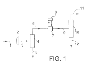
Referring to Figure 1, natural gas via a conduit 1 is
passed through an expansion means 2, whereby a stream is
obtained comprising liquid phase contaminant and a methane
enriched gaseous phase. The stream flows via a conduit 3
into a gas/liquid separator 4 wherein the two phases are
separated from each other. The liquid phase contaminant is
recovered via a conduit 5, whereas the methane enriched
gaseous phase is passed via a conduit 6 into a heat
exchanger 7. In heat exchanger 7 ethane is used an
external refrigerant whereby ethane is cooled by means of
an ethane/propane cascade 8 as depicted in more detail in
Figure 2. The cooling in heat exchanger 7 is such that a
liquid phase contaminant and a methane enriched gaseous
phase are formed. The stream which comprises these two
phases is then passed via a conduit 9 into a distillation
column 10 from which a further enriched methane enriched
gaseous phase is recovered via a conduit 11 and liquid
phase contaminant is recovered via a conduit 12.
In Figure 2 a suitable heat exchanger 7 is shown which
is based on an ethane/propane cascade which comprises an
ethane loop and a propane loop. In the ethane loop an
ethane stream is passed via a conduit 13 into an expander
14 (e.g. a turbine expander or a Joule-Thomson valve), and
the cooled ethane stream so obtained is passed via a
conduit 15 into the heat exchanger 7. A stream of warm
ethane is then passed from the heat exchanger 7 to a
recompressor 16 via a conduit 17 to increase the pressure
of the ethane stream. The compressed stream of ethane
CA 02735920 2011-03-03
WO 2010/034628 - 19 - PCT/EP2009/061798
obtained from recompressor 16 is then passed via a conduit
18 into heat exchanger 19 wherein the ethane stream is
cooled and at least partly condensed. Via the conduit 13
the ethane stream is then recycled to the expander 14. In
the propane loop a propane stream is passed via a conduit
20 into an expander 21 (e.g. a turbine expander or a Joule-
Thomson valve), and the cooled propane stream so obtained
is passed via a conduit 22 into the heat exchanger 19 of
the ethane loop. A stream of warm propane is then passed
from the heat exchanger 19 via a conduit 23 into a
recompressor 24 to increase the pressure of the propane
stream. The compressed stream of propane obtained from
recompressor 24 is then passed via a conduit 25 into a heat
exchanger 26 wherein the propane stream is cooled and at
least partly condensed by means of water or air. Via the
conduit 20 the propane stream is then recycled to the
expander 21.
In Figure 3 a preferred gas/liquid separator is shown
for carrying out step 3) of the present process. The stream
comprising liquid phase contaminant and a methane enriched
gaseous phase is passed via the conduit 3 into the
gas/liquid separator 4 via supply and distribution
assembly 27. Most of the liquid will flow down to the lower
end of the separator and leave the separator via the liquid
outlet 5. The gaseous stream comprising larger and smaller
droplets will flow upwards via liquid coalescer 28,
centrifugal separator 29 and a second liquid coalescer 30
to the top of the separator vessel, and leave the separator
vessel via gas outlet 6.
In Figure 4 another preferred gas/liquid separator is
shown for carrying out step 3) of the present process. The
stream comprising liquid phase contaminant and a methane
enriched gaseous phase is passed via the conduit 3 to a gas
inlet 31 in a housing 32 of the gas/liquid separator 4.
CA 02735920 2011-03-03
PCT/EP2009/061798
WO 2010/034628 - 2 0 -
The housing 32 further comprises a separating body 33 which
shows a large number of ducts 34 which are arranged around
a shaft 35, which provides an axis of rotation. Separating
body 33 has been composed of six discs 33a, 33b, 33c, 33d,
33e and 33f that have been combined by welding or gluing.
In the rotating separating body droplets of carbon dioxide
and/or hydrogen sulphide are separated from the natural
gas. The separated contaminants are discharged from the
housing via a contaminants outlet 36 which has been
arranged downstream of the separating body 33, and via the
discharge conduit 5. Purified natural gas leaves housing 32
via the gas outlet 6 arranged at the opposite end of the
housing 32.