Note: Descriptions are shown in the official language in which they were submitted.
CA 02735935 2016-05-20
INTEGRATED MULTI-MODE MAMMOGRAPHY/TOMOSYNTHESIS
X-RAY SYSTEM AND METHOD
10
This patent specification pertains to x-ray mammography and, more
specifically, to an
integrated system for selectively carrying out x-ray mammography and/or
tomosynthesis
imaging and a method of using such a system.
X-ray mammography has long been a screening modality for breast cancer and
other
lesions, and also has been relied on for diagnostic and other purposes. For
many years, the
breast image was recorded on x-ray film but more recently digital x-ray image
receptors
have come into use, as in the SeleniaTM mammography system available from
Hologic Inc.
of Bedford, MA and its division Lorad Corporation of Danbury, CT. For
mammograms, a
cone-shaped or pyramid-shaped x-ray beam passes through the compressed breast
and
forms a two-dimensional projection image. Any one of a number of orientations
can be
used, such as cranial-caudal (CC) or MLO (mediolateral-oblique) orientation.
More
recently, breast x-ray tomosynthesis has been proposed. The technology
typically involves
taking two-dimensional (2D) projection images of the immobilized breast at
each of a
number of angles of the x-ray beam relative to the breast and processing the
resulting x-
ray measurements to
CA 02735935 2016-05-20
2
reconstruct images of breast slices that typically are in planes transverse to
the x-ray
beam axis, such as parallel to the image plane of a marrunogram of the same
breast.
The range of angles is substantially less than in computerized tomography,
i.e.
substantially less than 1800, e.g. 115 . Tomosynthesis technology is described
in
U.S. Patent Application Ser. No. 10/723,486 filed November 26, 2003; a
prototype of
a unit with at least some of the described features was shown at the 2003
Radiological
Society of North America meeting in Chicago, Ill. Additional prototypes are in
clinical testing in this country as of the filing of this patent
specification. Other
approaches to tomosynthesis also have been proposed: see, e.g., U.S. Patents
Nos.
4,496,557, 5,051,904, 5,359,637, 6,289,235, and 6,647,092, published U.S.
Patent
Applications Nos. 2001/0038861, 2004/066882, 2004/0066884, and 2004/0066904,
and Digital Clinical Reports, Tomosynthesis (GE Brochure 98-5493, 11/98). How
to
reconstruct tomosynthesis images is discussed in DG Grant, "Tomosynthesis: a
three-
dimensional imaging technique", IEEE Trans. Biomed. Engineering, Vol BME-19,
#1, (January 1972), pp 20-28. See, also, U.S. Provisional Application Serial
No.
60/628,516, filed November 15, 2004, and entitled "Matching geometry
generation
and display of mammograms and tomosynthesis images". Mammography systems
can also be used in interventional procedures, such as biopsy, by adding a
biopsy
station (for example, the StereoLoe JJTM Upright Stereotactic Breast Biopsy
System,
which is available from Hologic, Inc.).
In clinical use, it can be desirable for a number of reasons to assess both
tomosynthesis images and conventional mammograms of the patient's breasts. For
example, the decades of conventional mammograms have enabled medical
professionals to develop valuable interpretation expertise. Mammograms may
offer
good visualization of microcalcifications, and can offer higher spatial
resolution
compared with tomosynthesis. Tomosynthesis images may have different desirable
characteristics ¨ e.g., they may offer better visualization of structures that
can be
obscured by overlying or underlying tissue in a conventional mammogram.
CA 02735935 2016-05-20
3
While the existing and proposed systems for x-ray mammography and
tomosynthesis offer
many advantages, it is believed that a need still exists for further
improvements to make
mammography/tomosynthesis more useful, and that it is particularly desirable
to make it
possible to use the same system in different modes of operation and thereby
reduce
acquisition and operating costs and provide greater clinical value and
convenience.
General
This patent specification describes examples of systems and methods for multi-
mode
breast x-ray imaging. A single system carries out breast imaging in modes that
include
standard mammography, diagnostic mammography, dynamic imaging such as with a
contrast agent and at different x-ray energies, tomosynthesis imaging,
combined standard
and tomosynthesis imaging during a single breast compression, needle
localization, and
stereotactic imaging with a biopsy station mounted to the system.
According to one aspect of the invention, a system for multi-mode breast x-ray
imaging is
provided which supports imaging using at least two imaging modes. At least one
imaging
mode differs from at least one other imaging mode by at least one imaging
procedure
selected from a group including, hut not limited to, receptor motion, anti-
scatter grid use,
exposure control and patient shielding. Breast imaging using each of the
different modes
may occur during a single compression and image scan of the breast or for
temporally
spaced compressions and scans.
The system supports a combination imaging mode wherein images are captured
using at
least two imaging modes (either during a single image scan or during different
image
scans) and wherein each of the at least two imaging modes uses at least one
different
imaging procedure. For dual mode capture using a single scan, such an
arrangement
facilitates fast capture of a plurality of images of different types without
decompression of
a patient's breast. As a result, the quantity and quality of information
available for
screening and diagnosis is substantially increased without concomitant
increase in
examination time, or patient discomfort. For dual mode capture using different
image
scans, such an arrangement allows different imaging
CA 02735935 2016-05-20
4
protocols to be implemented using a single imaging system. As a result, the
quantity
and quality of information available for screening and diagnosis is
substantially
increased without concomitant increase in examination equipment cost.
In an example of a system using the teachings of this patent specification, a
compression ann assembly for compressing and immobilizing the breast for x-ray
imaging, an x-ray tube assembly, and an x-ray image receptor can be angled
differently relative to each other for different imaging protocols and modes.
For
example, in first mode such as a mammography mode the receptor may be
positioned
generally normal to the plane of the x-ray tube assembly. In second mode, such
as a
tomosynthesis mode, as the x-ray tube assembly rotates through a first angular
range
the receptor rocks through a second angular range that is less than the first
angular
range such that the relative position of the x-ray tube assembly and x-ray
receptor is
offset from normal. In a preferred embodiment, the x-ray tube assembly and the
x-ray
receptor rotate and rock with. different angular displacements. As described
above,
the system supports a combination imaging mode wherein a plurality of images
are
captured during either during a single scan of the x-ray tube assembly or
during
multiple, temporally spaced scans, using at least two different imaging modes
(where
'temporally spaced' may mean a different scan during the same compression of
the
breast or a different scan using a later compression of the same breast). In
such an
arrangement, the receptor moves into a plurality of positions relative to the
x-ray
assembly, at least one different position for each of the modes of imaging
that are
performed during the single scan.
A patient shield can be removably mounted to the compression ann assembly to
provide a mechanical interlock against patient contact with the rotating x-ray
tube
assembly. In one embodiment, the patient shield may move to different
positions for
at least two different imaging modes of the multi-mode system. In an alternate
embodiment, the patient shield may be removed and/or replaced for each of the
different imaging modes of the multi-mode system.
A removable anti-scatter grid can be used that can cover the imaging area of
the x-ray
receptor in some modes but be removed for other modes. In a preferred
embodiment,
CA 02735935 2016-05-20
the anti-scatter grid is positioned parallel to and above the receptor in a
first mode, and
retracted in a second mode. However, as will be described in more detail
below, other
methods in addition to retraction may be used to remove the anti-scatter grid
and the present
invention is not limited to any particular method of grid removal.
According to another aspect of the invention, Automatic Exposure Controls
(AECs) are
varied in accordance with at least one of an imaging mode and a breast
density.
The exemplary system further includes a breast compression paddle that is
laterally
movable, under manual control or when motorized and operating under software
control.
The compression paddle can shift automatically depending on the view to be
acquired. For
example, the paddle can be centered on the x-ray receptor for a CC view,
shifted to one
lateral side of the receptor for an MLO view of one breast and to the other
lateral side of the
receptor for an MLO view of the other breast. The paddle can be automatically
recognized by
the system when mounted so that the shifts can be adjusted to the type of
paddle.
The compression paddle can be easily removable from a support that has a
mechanism for laterally moving the paddle and for allowing the paddle to tilt
for better
conformance with the breast for selected image modes but locking the paddle
against tilt for
other modes. With the movement mechanism in the support and not integral with
the paddle,
the paddle can be simple and inexpensive, and easy to mount to and remove from
the
support. A number of relatively inexpensive paddles of different sizes and
shapes can be
provided and conveniently interchanged to suit different procedures and
patients.
Accordingly, in one aspect, the present invention resides in a multi-mode
breast x-ray imaging
system comprising: a tube arm assembly comprising an x-ray source, and a
compression arm
assembly comprising a face shield and an x-ray receptor, the face shield
positioned between
the x-ray source and the x-ray receptor, wherein the x-ray source and x-ray
receptor are
configured to perform a single image scan which generates images using at
least two different
imaging modes and wherein at least one imaging procedure is executed
differently in each of
the at least two different imaging modes during the single scan, wherein the x-
ray source
moves relative to the compression arm assembly in one of the at least two
different imaging
modes and the face shield is configured to stay in one position outside of a
path of the x-ray
source when the x-ray source moves relative to the compression arm assembly.
CA 02735935 2016-05-20
5a
In another aspect, the present invention resides in a method of acquiring both
2D and 3D
images of a patients breast using a multi-mode imaging system which comprises
an x-ray
tube assembly and a compression arm assembly comprising a face shield and an x-
ray
receptor, the face shield positioned between the x-ray tube assembly and the x-
ray receptor,
wherein the patient's breast is compressed between the x-ray tube assembly and
the x-ray
receptor and wherein the 2D and 3D images are acquired without decompressing
the
breast includes the steps of: moving the x-ray tube assembly to a plurality of
positions
associated with 2D and 3D imaging modes; and executing at least one imaging
procedure
differently for each of the 2D and 3D modes during the single scan; wherein
the x-ray tube
assembly moves relative to the compression arm assembly in one of the 2D and
3D
imaging modes and the face shield is configured to stay in one position
outside of a path
of the x-ray tube assembly when the x-ray tube assembly moves relative to the
compression arm assembly.
In yet another aspect, the present invention resides in a multi-mode breast x-
ray imaging
system comprising: a tube arm assembly comprising an x-ray source; and a
compression arm
assembly comprising a face shield and an x-ray receptor, the face shield
positioned between
the x-ray source and the x-ray receptor, wherein the x-ray source and x-ray
receptor are
configured to operate using at least two different imaging modes and wherein
at least one
imaging procedure is executed differently in each of the at least two
different imaging modes
during the single scan, wherein the x-ray source moves relative to the
compression arm
assembly in one of the at least two different imaging modes and the face
shield is configured to
stay in one position outside of a path of the x-ray source when the x-ray
source moves relative
to the compression arm assembly.
Brief description of the drawing
Fig. 1 is a perspective view of a gantry and an acquisition workstation in
accordance with an
example of the disclosed system.
Fig. 2 is an enlarged view of a portion of the system of Fig. 1, with a tube
arm assembly in a
rotated position.
CA 02735935 2016-05-20
6
Fig. 3 is a front elevation of the apparatus of Fig. 2.
Fig. 4 is a side view of a gantry with a biopsy station and a spacer, with
schematic
illustration of other mechanisms.
Fig. 5 is an enlarged view of a portion of Fig. I.
Fig. 6 is a block diagram of the disclosed system when connected to other
systems.
Fig. 7 is a flow chart illustrating a general work flow for the disclosed
system.
Fig. 8 is a flow chart illustrating one of several examples of work flow for a
standard
mammography mode.
Fig 9 is a flow chart illustrating one of several examples of work flow for an
image
detector subsystem in the standard mammography mode.
Fig. 10 is a perspective view of the structure of Fig. 4.
Fig. 11 is similar to Fig. 2 but shows a tube ann assembly angled differently.
Fig. 12 is a front elevation of the structure of Fig. 11.
Fig. 13 is a flow chart illustrating one of several examples of work flow for
a
tomosynthesis mode.
Fig. 14 is a flow chart illustrating one of several examples of work flow for
an image
detector subsystem in the tomosynthesis mode.
Fig, 15 is a flow chart illustrating one of several examples of work flow for
a
combination mode.
CA 02735935 2016-05-20
7
Fig. 16 is a flow chart illustrating one of several examples of work flow for
an image
detector subsystem in the combination mode.
Fig. 17 is an enlarged side view of a structure for removably mounting a
breast
compression paddle.
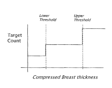
Figure 18 is a graph illustrating a relationship between target count and
breast thickness.
Figure 19A is a flow diagram illustrating exemplary steps for varying target
count using
breast density information.
Figure 19B is a graph illustrating various relationships between target count
and breast
density.
Detailed description
In describing examples and preferred embodiments illustrated in the drawings,
specific
terminology is employed for the sake of clarity. However, the disclosure of
this patent
specification is not intended to be limited to the specific terminology so
selected and it is
to be understood that each specific element includes all technical equivalents
that operate
in a similar manner.
Figs. 1-6 illustrate a non-limiting example of a multi-mode mammography/
tomosynthesis
system comprising a gantry 100 and a data acquisition work-station 102. Gantry
100
includes a housing 104 supporting a tube arm assembly 106 rotatably mounted
thereon to
pivot about a horizontal axis 402 (Fig. 4) and carrying an x-ray tube assembly
108. X-ray
tube assembly 108 includes (1) an x-ray tube generating x-ray energy in a
selected range,
such as 20-50 kV, at mAs such as in the range 3-400 mAs, with focal spots such
as a
nominal size 0.3 mm large spot and nominal size 0.1 mm small spot (2) supports
for
multiple filters such as molybdenum, rhodium, aluminum, copper, and tin
filters, and (3)
an adjustable collimation assembly selectively collimating the x-ray beam from
the focal
spot in a range such as from 7x8 cm to 24x29 when measured at the image plane
of an x-
ray image receptor included in the system, at a maximum source-image distance
such as
75 cm. Also mounted on housing 104, for rotation about the same axis 402, is a
compression arm assembly 110 that comprises a compression plate 122 and a
receptor
housing 114 having an upper surface 116 serving as a breast plate and
enclosing a detector
subsystem system 117 comprising a flat panel x-ray receptor 502 (Fig. 5), a
retractable
anti-scatter grid 504 and a mechanism 506 for driving and retracting anti-
CA 02735935 2016-05-20
8
scatter grid 504. Housing 104 also encloses the following components
schematically
illustrated in Fig. 4: a vertical travel assembly 404 for moving tube arm
assembly 106
and compression arm assembly 110 up and down to accommodate a particular
patient
or imaging position, a tube arm assembly rotation mechanism 406 to rotate tube
arm
assembly 106 about axis 402 for different imaging positions, a detector
subsystem
rotation mechanism 408 for rotating components of detector subsystem 117 (such
as
x-ray receptor 502) about axis 402 to accommodate different operations modes,
and
couple/uncouple mechanism 410 to selectively couple or uncouple tube arm
assembly
106 and compression arm assembly 110 to and from each other, and tube arm
assembly 106 and detector subsystem 117 to and from each other. Housing 104
also
encloses suitable motors and electrical and mechanical components and
connections
to implement the functions discussed here.
A patient shield 200, schematically illustrated in Fig. 2, can be secured to
compression arm assembly 110 to provide a mechanical interlock against patient
contact with the rotating x-ray tube arm assembly 106 and reduce patient
interference with the x-ray image capture. One exemplary patient shield is a
shifting patient shield that is positioned generally parallel to but outside
the path of
x-ray beams from source 108. The shifting face shield is supported by an
extension arm that extends laterally from the compression arm assembly and
permits movement of the face shield along a z axis (indicated by line 202)
between
a patient access position and a patient shielding position as described in
U.S.
Provisional application 61/075,226. In various embodiments the patient shield
may be removably secured either to the extension arm, compression arm assembly
or the x-ray source assembly 108 to facilitate removal and/or replacement of
shields for different imaging modes. In various embodiments, the face shield
may
be of fixed size, or may be adjustably sized. An example of an adjustable face
shield is disclosed in U.S. 7,315,607, where the face shield is positioned to
slide
vertically along a y-axis, as indicated by arrow 201, up into the x-ray
assembly.
The vertical movement removes the face shield to allow for patient positioning
as
well as allows the shield to be selectively positioned to provide shields of
different
sizes for different imaging modes. Alternate embodiments are also envisioned
wherein the face shield is programmed to shift laterally along an x-axis in
response
to a selection of a particular
CA 02735935 2016-05-20
9
imaging mode. Such an embodiment is described in U.S. patent 7,245,694 issued
July 17, 2007 to Hologic Inc. In summary, it is anticipated that different
shields or
shield arrangements may be used in a system of the present invention which
supports a combination imaging mode, wherein the shield is removable or moves,
either automatically or manually, between at least two positions for at least
two
different imaging modes.
Work-station 102 comprises components similar to those in the Selenialm
mammography system, including a display screen (typically a flat panel display
that
may include touch-screen functionality), user interface devices such as a
keyboard,
possibly a touch-screen, and a mouse or trackball, and various switches and
indicator
lights and/or displays. Work-station 102 also includes computer facilities
similar to
those of the SeleniaTM system (but adapted through hardware, firmware and
software
differences) for controlling gantry 100 and for processing, storing and
displaying data
received from gantry 100. A power generation facility for x-ray tube assembly
108
may be included in housing 104 or in work-station 102. A power source 118
powers
work-station 102. Gantry 100 and work-station 102 exchange data and controls
over
a schematically illustrated connection 120.
As illustrated in Fig. 6, additional storage facilities 602 can be connected
to work-
station 102, such as one or more optical disc drives for storing information
such as
images and/or for providing information to work-station 102 such as previously
obtained images and software, or a local printer (not shown). In addition, the
disclosed system can be connected to a hospital or local area or other network
604,
and through the network to other systems such as a soft copy workstation 606,
a CAD
(Computer Aided Detection) station 608 for computer- processing mammography
and/or tomosynthesis images to identify likely abnormalities, an image printer
610 for
printing images, a technologist workstation 612, other imaging systems 614
such as
other mammography systems or systems for other modalities for exchange of
images
and/or other information, and to a PACS (Picture Archiving) systems 616 for
archiving images and other information and/or retrieving images and other
information.
CA 02735935 2016-05-20
The illustrated system has several modes of operation. An example of typical
workflow generally applicable for each mode is illustrated in Fig. 7, and
several
examples of operational modes are discussed below. Of course, this is only one
example and workflow steps may be arranged differently. In all modes, the
operator
5 can perform x-ray exposure using manual setting of technic factors such
as mA and
mSec, or can use an Automatic Exposure Control (AEC) method as known in the
art
to set the exposure time, kV and filter modes for an image, for example by
using a
short, low-x-ray dose pre-exposure. Work-station 102 is set up to record the
exposure
technic information and associate it with the breast image for later review.
During an exemplary Automatic Exposure Control (AEC) method, a short (e.g., ¨5
insec) an x-ray is taken (either at a low dose, or full dose) and the image
receptor's
image is read by a computer process. This initial x-ray is often referred to
as a 'scout'
image. The computer process uses information from the scout image to identify
the
breast's radio-density and to calculate the correct final x-ray tube exposure
voltage
kVp, current mAs, and exposure time for delivering a desired x-ray dose be
obtained
prior to performing mammography or tomosynthesis.
In an alternate embodiment described in U.S. Patent 7,245,694, in a
combination
mammographyitomosynthesis system when a tomosynthesis scan follows a
mammogram, the mammogram exposure data may be used to estimate tomosynthesis
exposure techniques. In still another alternate embodiment, a first
tomosynthesis
image may be used to as the 'scout' image to estimate the appropriate exposure
factors for the remaining images in the tomosynthesis sequence.
Lookup tables have historically been used to identify appropriate kVp and mAs
for
desired exposures using scout or mammogram images. Look-up tables arc reliable
in
2D mammography systems which position the x-ray source normal to the detector
and
utilize anti-scatter grids to minimize radiographic scatter. In such systems
the
detector count rate may be fixed, with exposure dosing being controlled by
varying
the kVp and mAs. Referring briefly to Figure 18A a lookup table 1800 is shown
that
provides exposure parameters for a tomosynthesis or mammography system based
on
a scout image reading.
CA 02735935 2016-05-20
11
However tomosynthesis systems which do not maintain a constant perpendicular
relationship between the receptor and the x-ray source are not able to use an
anti-scatter
grid. The present invention recognizes that such systems may benefit from
improved
exposure control techniques having the ability to vary the target detector
count to
compensate for radiographic scatter, where the detector count relates a count
of photons to
a desired x-ray dose. In a preferred embodiment the detector count is varied
in accordance
with a thickness of the imaged breast. Thus thicker breasts, which experience
a higher
radiographic scatter, have a higher detector target count. Varying the
detector count in
accordance with breast thickness ensures that image quality of the breasts is
maintained
despite increased scatter. Accordingly, in one embodiment the present
invention
compensates for the increased scatter by varying the target count in response
to at least
one of a breast thickness or a breast density. Image exposure is controlled by
reducing the
detector target counts for compressed breasts having a thickness that is below
the lower
breast thickness threshold, and increasing detector target counts for
compressed breasts
having a thickness that is above the upper breast thickness threshold as shown
in Figure
18.
According to a further aspect of the invention and as shown in Figures 19A and
19B,
target counts are varied in response to breast density rather than breast
thickness. Figure
19A is a flow diagram illustrating a process 1900 according to the present
invention which
suggests a method of varying target count based on breast density. At step
1910 the breast
is compressed and at step 1912 a low voltage scout pulse is emitted from the x-
ray source.
At step 1914 the x-ray detector values are quickly read and evaluated to
locate the portion
of the breast associated with the highest signal attenuation, i.e., the
'target'. At step 1916
a target count associated with this attenuation is then selected, for example
from a
previously populated lookup table. In general, as is known in the art, the
higher the
attenuation at the target, the higher the target counts. Figure 19B is a graph
that illustrates
several exemplary functions for varying the target count in response to breast
density, for
example where the target count increases linearly (as shown by line 1920),
stepwise
(1922) or according to a predetermined function (1924).
CA 02735935 2016-05-20
12
Thus, when a multi-mode imaging system is used in combination mode, several
different
AEC techniques and/or parameters may be used during a single sweep of the x-
ray tube
assembly arm (or between different sweeps of the x-ray tube assembly).
In addition, although the table illustrates that a common kV, mA and count is
provided for
a given thickness, it is also envisioned that the AEC values may be customized
for
different imaging positions along the tomosynthesis path to accommodate for
different
types of radiographic scatter resulting from different x-ray source/receptor
angular
relationships, whether the imaging positions be associated with different
imaging modes
(such as mammography and tomosynthesis) or within the same imaging mode (i.e.,
different tomosynthesis imaging angles).
In standard mammography mode, typically used for screening mammography, tube
arm
assembly 106 and compression arm assembly 110 are coupled and locked together
by 410
in a relative position such as seen in Fig. 1, such that an x-ray beam from x-
ray tube
assembly 108 illuminates x-ray receptor 502 when the patient's breast is
compressed by
compression device 112. In this mode, the system operates in a manner similar
to said
SeleniaTM system to take a mammogram. Vertical travel assembly 404 and tube
arm
rotation mechanism 406 can make vertical adjustments to accommodate a patient,
and can
rotate tube arm assembly 106 and compression arm assembly 110 together as a
unit about
axis 402 for different image orientations such as for CC and for MLO images.
For
example, tube arm assembly 106 and compression arm assembly 110 can rotate
between (-
195 ) and (+150 ) about axis 402. As in the SeleniaTM system, compression
device 112
includes a compression paddle 122 that can move laterally, in a direction
along the chest
wall of a patient, to adjust for different imaging orientations. However, as
described
further below, the mechanism for supporting and moving compression paddle 122
is
different. Typically, anti-scatter grid 504 is over x-ray receptor 502 in the
standard
mammography mode to reduce the effect of x-ray scatter. Fig. 8 illustrates a
typical
workflow for an exposure in standard mammography mode, and Fig. 10 illustrates
an
example of the operation of detector subsystem 117 in standard mammography. Of
CA 02735935 2016-05-20
12A
course, these are only examples; other workflow steps or orders of steps can
be used
instead.
In a diagnostic mode, the patient's breast can be spaced from upper surface
116, for
example by an x-ray translucent spacer gantry 1002 (Fig. 10), with the system
otherwise
similar to Fig. 1, for a magnification of up to 1.8, for example. In this
mode, as in
standard mammography, tube arm assembly 106 and compression arm assembly 110
are
locked to each other and can move up or down and rotate about axis 402 for
different
image orientation. A different spacer 1002 can be used for a different degree
of
magnification. Also, differently shaped or dimensioned compression paddles 122
can be
used for different breast compression effects. The x-ray tube in x-ray tube
assembly 108
can be set to a smaller focal spot size to improve a diagnostic image. In this
mode, anti-
scatter grid 504 typically is retracted or otherwise removed when
magnification is used
such that grid 504 is completely out of the image. The user can elect not to
use a spacer
1002 in diagnostic imaging, in which case anti-scatter grid 504 can be used
over the entire
image.
In a dynamic imaging mode, a number of breast images are taken while the
patient's
breast remains compressed. In one technique, an agent such as iodine is
injected into the
patient and after a suitable waiting time such as about one minute for a
maximum uptake,
two images breast are taken in rapid succession, for example one at an x-ray
energy just
above the K-edge of iodine and one at an energy just below the K-edge.
CA 02735935 2016-05-20
13
Altematively, a succession of breast images can be taken at a single x-ray
energy
band or bands just above and below the K-edge, or at another x-ray energy
range, to
track the uptake of agent over time. Another technique adds taking a baseline
breast
image before or soon after injecting the agent and using it together with
later breast
images to generate subtraction images that provide better visualization of
anatomy
that may be of interest. Still another dynamic imaging mode technique
comprises
injecting a contrast agent and taking a succession of images over a period
such as 5-7
minutes, for example one image every minute, and processing the image data to
generate for each pixel, or at least for each pixel of interest, a histogram
of the change
in the pixel value, to thereby use the manner in which pixel values change to
differential abnormal tissue. For this mode, work-station 102 can store preset
data
that commands gantry 100 and work-station 102 to take a desired sequence of
images
for the dynamic mode technique selected by the operator, such that the command
data
sets the appropriate parameters such as x-ray energy, dose, timing of images,
etc.
Alternatively, such processing to assess changes in pixel values can be done
for a
region of interest rather than over individual pixels, to produce information
such as a
measure of changes in the average pixel values in the region of interest.
In tomosynthesis mode, tube arm assembly 106 and compression arm assembly 110
are decoupled by unit 410 such that compression arm assembly 110 stays in one
position, compressing the patient's breast, while tube arm assembly 106
rotates about
axis 402, for example between the position illustrated in Fig. 2 to that
illustrated in
Fig. 11, or +15 relative to compression arm assembly 110. In one embodiment,
during tomosynthesis mode the x-ray tube assembly rotates in an arc shaped
path
within a plane although this is not a requirement of the invention. Other
tomosynthesis embodiments wherein the x-ray tube moves in a non-arc shaped
path,
for example through movement of the source outside of the plane of the x-ray
assembly, or alternatively movement of the x-ray source vertically within the
plane,
are also envisioned.
Tomosynthesis can be carried out for different image orientations, so that
compression arm assembly 110 can be rotated about axis 402 (alone or together
with
assembly 106) for a desired image orientation and locked in place, and then
tube arm
CA 02735935 2016-05-20
14
assembly 106 can be rotated relative to that position of compression arm
assembly
110 for tornosynthesis imaging over 15 or some other desired angular range.
In one
example, 11 images are taken during an angular sweep of tube arm assembly 106,
one
every approximately 3 . However, a different number of images can be taken,
for
example up to 21 during a single sweep. For tornosynthesis images, the x-ray
tube in
x-ray tube assembly 108 continuously rotates and the x-ray tube is pulsed for
each
image, for example, for x-ray energy pulses each lasting approximately 100
mSec,
although pulses of different duration can be selected. Alternatively, the
rotational
motion can stop for taking each image, or continuous motion without pulsing
can be
used (and the timing of data measurements relied to define pixel values). As
seen in
Figs. 2, 3, 5, 11 and 12, in this mode mechanism 506 fully retracts anti-
scatter grid
504 away from x-ray receptor 502 so grid 504 is out of the image. Alternate
methods
of removing the anti-scatter grid from the image, such as ejecting the grid
out of a
side of the receptor housing 114 or otherwise accessing and removing the grid
are also
contemplated by this invention.
Also as seen in these Figs., while the breast remains immobilized in
compression arm
assembly 110 during the angular sweep of tube arm assembly 106, in one
embodiment
the x-ray receptor 502 rocks within receptor housing 114_ In this rocking
motion,
controlled by unit 408 (Fig. 4), a line normal to the image face of x-ray
receptor 502
may keep pointing to the focal spot of the x-ray tube in x-ray tube assembly
108.
Alternatively, the rotation of tube arm assembly 106 and rocking of x-ray
receptor
502 can be through different angles; for example, tube arm assembly 106 can
rotate
through 15 while x-ray receptor 502 rocks through 5 , i.e. the rocking angle
can be an
amount one-third that of assembly 108. In general, the receptor 502 rocks in
concert
with, but with a smaller angular displacement, from the x-ray tube assembly.
Although a one-third relationship has been described, the present invention is
not
limited to any particular fractional angular relationship between the assembly
and the
receptor, and the present invention envisions systems wherein the detector is
stationary during imaging.
Synchronous rotation of tube arm assembly 106 and rocking of x-ray receptor
502 can
be achieved by controlling separate motors for each or, alternatively, through
using a
CA 02735935 2016-05-20
motor to drive tube arm assembly 106 and a mechanical coupling between the
rotation of tube arm assembly 106 and rocking of x-ray receptor 502. Image
data
can be obtained and processed into tomosynthesis images for display and/or
storage as described for example in co-pending patent application Ser. No.
5 10/723,486 or in U.S. Provisional Application No. 60/628,516, filed
November 15,
2004. Fig. 13 illustrates a typical workflow for tomosynthesis mode operation,
and
Fig. 14 illustrates an example of the operation of detector subsystem 117 in
that
mode. Again, these are only examples, and other steps or orders of steps can
be
used instead.
It should be noted that although in preferred embodiments the receptor rocks
such that
it is positioned offset from normal to the x-ray source, this is not a
requirement of the
invention. Alternate embodiments where the receptor rotates along the same
angular
displacement and synchronous to the x-ray source are also contemplated. In
addition,
embodiments where the x-ray receptor moves linearly or laterally in a plane,
rather
than rocking, are within the scope of the present invention. In addition, in
embodiments wherein the x-ray source assumes a non-arc shaped path, systems
wherein the receptor rotates or tilts in a manner related to the x-ray source
movement
are contemplated by the present invention_ Of course other embodiments wherein
the
detector remains stationary are also contemplated by this invention.
In a combination mode, during a single compression of the patient's breast the
system
takes a conventional mammogram and tomosynthesis images. In this mode, while
the
breast remains compressed in compression arm assembly 110, (1) tube arm
assembly
106 sweeps and x-ray receptor 502 rocks, each through an appropriate angle,
and
exposures are taken for tomosynthesis images, and (2) a standard mammogram is
taken. The standard mammogram can be taken at a 0 relative angle between tube
arm assembly 106 and a normal to the imaging plane of x-ray receptor 502, and
can
be taken before or after the tomosynthesis images are taken or between the
taking of
two successive tomosynthesis images. Typically, each tomosynthesis image
utilizes
substantially lower x-ray dose than the standard mammogram. For example, the
total
x-ray dosage for tomosynthesis imaging in one sweep of tube arm assembly 106
can
be approximately the same as that for a single standard mammogram, or up to
CA 02735935 2016-05-20
16
approximately three times that dosage. The relationship between the two
dosages can
be user-selected. Figure 15 illustrates an example of workflow for the
combination
mode, and Fig. 16 illustrates an example of the operation of detector
subsystem 117 in
that mode. Again, these are examples, and different steps or orders of steps
can be
used instead. For example, a preferred approach may be to take the standard
tnammogram first, then move aim 106 to one end of its rotational range for
tomosynthesis and take the tomosynthesis images. The order in which the two
types
of images are taken may be optimized such that the overall imaging time is
minimized, and an order that achieves such minimization can be the preferred
order.
The exposure (tube current mA, tube voltage kVp, and exposure length msec)
techniques for the standard mammogram and the tomosynthesis exposures can be
set
manually, by using automatic methods or using the methods described above. If
the
standard mammogram is taken first, its exposure techniques can be used to set
an
optimal technique for the subsequent tomosynthesis images, and vice versa. The
exposure technique can be modified dynamically, if the software senses that
the signal
reaching the image receptor is either too low or too high and adjust
subsequent
exposures as needed.
In a stereotactic mode, during a single compression of the patient's breast at
least two
images of taken, for example one at (+15)* angle and one at (45 ) angle of
tube arm
assembly 106 relative to compression arm assembly 110, although other angles
can be
used and more images can be taken. X-ray receptor 502 can remain in place for
this
procedure, or can be rocked through a selected angle, for example through an
angle
sufficient to maintain the same orientation of the imaging surface of receptor
502
relative to tube arm assembly 106. A spacer 1002 can be used for
magnification. If
x-ray receptor 502 remains in place despite rotation of arm 106, or if spacer
1002 is
used, anti-scatter grid 504 is fully retracted; if x-ray receptor 502
maintains its
orientation relative to tube aim assembly 106 and not spacer 1002 is used,
anti-scatter
grid 504 need not be retracted. As is known in the art, the two or more images
can be
used to identify the location of a lesion, so that needle biopsy can be used,
for
example with an upright needle biopsy station 412 (Fig, 4) in a manner similar
to that
used with the commercially available SeleniaThl system and StereoLoc JJTM, A
compression paddle 122 appropriate for needle biopsy typically is used when
taking
CA 02735935 2016-05-20
17
the stereotactic images. Alternatively, some or all of the images taken in the
tomosynthesis mode and/or in the combined mode can be used to identify the
location
of a lesion for biopsy, in which case a compression paddle 122 appropriate for
the
purpose typically is used when taking the images.
In needle localization mode, x-ray images can be taken after a biopsy or other
needle
is inserted into the compressed breast. For this purpose, imaging such as in
the
stereotactic mode, the tomosynthesis mode, or the combined mode can be used.
In the disclosed system, compression paddle 122 is movable laterally, as
generally
described in co-pending U.S. Patent Application Publication No. 2005/0063509
Al. In addition, compression paddle 122 can pivot about an axis along the
patient's chest wall to conform the breast shape in certain procedures, as
discussed
in said U.S. Patent 5,706,327. However, in the system of this patent
specification
compression paddle 122 is mounted differently and moves in a different manner.
As illustrated in Figs. 5 and 17, compression paddle 122 is removably mounted
to a
support 510 that moves up and down compression arm assembly 110 as needed for
breast compression. To mount compression paddle 122 onto 510, a projection
compression paddle 122a of the paddle engages a projection 510a of the
support, and
a projection 122b of the paddle latches onto projection 510b of the support.
Projection 510a is spring-loaded, such as by a spring schematically
illustrates at 510c
to allow for pivoting compression paddle 122 about an axis where it latches
onto 510,
as illustrated by arrow A, for better conformance with the compressed breast
in some
imaging protocols. Other imaging protocols may require compression paddle 122
not
to pivot, in which case projection 510a is locked in place by a locking
mechanism in
510 (not shown) to keep compression paddle 122 in place relative to support
510,
The locking mechanism can be manually set to a lock position, and manually
unlocked by the operator. Alternatively, the locking mechanism can be
controlled
through an operator input at gantry 100 or work-station 102. A sensing
mechanism
can be included to sense whether compression paddle 122 is locked against
pivoting,
to provide information that work-station 102 can use for setting imaging
protocols
CA 02735935 2016-05-20
18
such as for automated breast compression and automated exposure methods. Two
knobs 510d, one on each lateral side of support 510, can be manually rotated
to move
projection 510b and thus compression paddle 122 laterally such that it
compress a
breast that is not centered laterally on upper surface 116, for example for
MLO
imaging. Each knob 510d can operate a mechanism such as an endless screw
rotating
in a nut secured to projection 510b. Alternatively, or in addition, projection
510b and
thus compression paddle 122 can be driven laterally by a motor, under control
of
operator switches or other interface at gantry 100 or at work-station 102, or
automatically positioned laterally under computer control.
Importantly, compression paddle 122 is driven for lateral movement by
components
that are a part of support 510. Thus, compression paddle 122 can be simple
structure,
and can even be disposable, with a new one used for each patient or for only a
few
patients. This can simplify and reduce the cost of using the system, because
an
imaging facility usually stocks a number of different paddles for different
purposes.
If the lateral movement mechanism is integral with a compression paddle, the
paddle
assembly is considerably larger, heavier and more expensive. But with a
compression
paddle 122 that relies for lateral movement on support 510, and is easily
mounted by
hand and without tools to support 510, by sliding compression paddle 122a into
projection 510a and latching projection paddle 122b onto projection 510b, and
is
easily removed by reversing the process, the expense of keeping a number of
different
compression paddles in stock or replacing paddles with new ones is greatly
reduced,
as are the time and convenience when changing from one type of compression
paddle
to another. Compression paddle 122 can include a bar code that is
automatically read
by a bar code reader in support 510, to keep work-station 102 informed of the
paddle
currently mounted to support 510, for use in automating imaging protocols. For
example, the bar code information can be checked to ensure through computer
processing that the type of paddle that is currently mounted on support 510
matches
the imaging that will be commanded, and the information from the sensor for
whether
compression paddle 122 is locked in non-tilting mode can be used to
automatically
make adjustments for compression height to ensure accurate automatic x-ray
exposure
operation. Further, the bar code information identifying the paddle can be
used to
CA 02735935 2016-05-20
19
automatically set collimation in x-ray tube assembly 108 so that the x-ray
beam
matches the size and shape of the currently installed compression paddle 122.
Thus a system for multi-mode breast x-ray imaging that supports at least two
imaging
modes has been shown and described. Multiple different imaging modes may be
used
in a single breast compression or alternatively using temporally spaced
compressions.
The imaging modalities include, but are not limited to, mammography, dynamic
imaging mode, diagnosis mode, tomosynthesis, combination mode and stereotactic
mode. The system facilitates imaging protocols wherein at least one imaging
mode
differs from at least one other imaging mode for at least one imaging capture
procedure selected from a group including, but are not limited to receptor
motion, x-
ray source location, anti-scatter grid use, exposure control and patient
shielding.
The system further supports a combination imaging mode wherein images are
captured using at least two imaging modes during a single image scan and
wherein
each of the at least two imaging modes differs by at least one image capture
procedure
during the single scan. Such an arrangement facilitates fast capture of a
plurality of
images of different types without decompression of a patient's breast. As a
result, the
quantity and quality of information available for screening and diagnosis is
substantially increased without concomitant increase in examination time or
patient
discomfort.
The above specific examples and embodiments are illustrative, and many
variations can be introduced on these examples and embodiments without
departing from the scope of the disclosure or from the scope of the appended
claims. For example, elements and/or features of different illustrative
embodiments may be combined with each other and/or substituted for each other
within the scope of this disclosure and appended claims.