Note: Descriptions are shown in the official language in which they were submitted.
CA 02736033 2011-03-03
WO 2010/033851 PCT/US2009/057548
TITLE
ELECTRO-OPTICAL RADIATION COLLECTOR FOR ARC FLASH DETECTION
TECHNICAL FIELD
[0001] This disclosure relates to electro-optical radiation collection and/or
sensing
devices and, in particular, to a versatile electro-optical radiation collector
that may be
used for arc flash detection.
BREIF DESCRIPTION OF THE DRAWINGS
[0002] The accompanying drawings illustrate various exemplary embodiments of
the
present system and method and are a part of the specification. Together with
the
following description, the drawings demonstrate and explain the principles of
the
present system and method. The illustrated embodiments are examples of the
present
system and method and do not limit the scope thereof.
[0003] Figure 1A is a block diagram of one embodiment of a system for
providing
arc flash protection to a power system;
[0004] Figure 1 B is a block diagram of another embodiment of a system for
providing arc flash protection to a power system;
[0005] Figure 2 is a block diagram of an arc flash protection device;
[0006] Figure 3 illustrates one embodiment of an electro-optical radiation
collector;
[0007] Figure 4A is an exploded view of another embodiment of an electro-
optical
radiation collector;
[0008] Figure 4B is an exploded view of a cap of an electro-optical radiation
collector;
[0009] Figure 5 is a block diagram of one embodiment of an arc flash
protection
device configured to receive electro-optical radiation collected by an electro-
optical
radiation collector;
[0010] Figure 6 is block diagram of another embodiment of an arc flash
protection
device configured to receive electro-optical radiation collected by one or
more electro-
optical radiation collectors; and
[0011] Figure 7 is a block diagram of another embodiment of an arc flash
protection
device configured to receive electro-optical radiation collected by one or
more electro-
optical radiation collectors.
1
CA 02736033 2011-03-03
WO 2010/033851 PCT/US2009/057548
DETAILED DESCRIPTION
[0012] Arc flashes pose a serious risk to both personnel and equipment in the
vicinity of a flash. An arc flash may produce intense electro-optical (EO)
radiation
(including visible light) in the area of the arc. In addition, an overcurrent
condition may
be created on electric conductor(s) that feed the arc.
[0013] An arc flash detection unit (AFDU) may be configured to monitor a
portion of
a power system (e.g., an enclosure, housing, or the like). The AFDU may be
configured to detect an arc flash event based on stimulus received from the
power
system. The AFDU may make use of various different types of stimulus
including, but
not limited to: EO radiation detected in the vicinity of the power system,
current levels
within the power system, voltage levels at various points within the power
system, heat,
chemical detection, pressure differentials (e.g., sound), detection of
particulates within
an enclosure, or the like.
[0014] The time required to detect an arc flash event by a protection system
(e.g.,
an AFDU) may be used to determine a total time required to clear the arc flash
(e.g.,
the total time required to clear the arc flash may be a sum of the time
required to detect
the flash plus the time required to trip protective elements responsive to the
detection).
The time required to clear the arc flash may be referred to as a "total arcing
time,"
which may be used to calculate the incident energy released by the arc flash
event
(given the arc current, resistance, conductor gap, and the like). The
detection time of
an arc flash protection system may vary depending upon the configuration of
the
protection system (e.g., the sensitivity of the system). System sensitivity
may be
selected to provide a balance between providing adequate arc flash protection
and
preventing misoperation (e.g., detecting false positives).
[0015] The "Guide for Performing Arc Flash Hazard Calculations, " which is
promulgated by the Institute of Electrical and Electronics Engineers (IEEE) as
IEEE
1584, provides several means for calculating arc flash incident energy, one of
which is
provided below in Equation 1:
[0016] Log(En,)=K,+K2+1.0811=Log(IQ)+0.0011=G Eq.1
[0017] In Equation 1, EN is the arc flash incident energy, K, is a switchgear-
dependent constant value (depending upon whether the switchgear is in an open
or box
configuration), K2 is a constant (0 for ungrounded or high-resistance grounded
2
CA 02736033 2011-03-03
WO 2010/033851 PCT/US2009/057548
switchgear and -0.113 for grounded systems), la is the maximum arcing current,
and G
is a gap between conductors within the switchgear.
[0018] The IEEE 1584 standard further provides means for determining an arc-
protection boundary as follows:
X
[0019] Db = 4.184. C f = En = Ott . EW Eq. 2
b
[0020] In Equation 2, Db is the distance of the boundary from the arcing
point, Cf is a
voltage constant (1.0 for voltages above 1 kV), Eõ is the normalized arc flash
incident
energy (e.g., calculated per Equation 1 above), Eb is the incident energy at
the
boundary (5.0 J/cm2 for bare skin), and x is a distance exponent constant
(0.973 for 5
kV switchgear).
[0021] The protection boundary may determine where maintenance personnel may
safely work in relation to the switchgear and/or may determine what, if any,
protective
gear should be used by the personnel.
[0022] Other standards exist for calculating arc flash energy to determine
appropriate proximity and/or protective gear requirements. For instance, the
National
Fire Protection Association (NFPA) provides for the calculation of an arc
thermal
performance value (ATPV), which is similar to the IEEE 1584 arc flash incident
energy.
The ATPV may determine a proximity boundary in which maintenance personnel may
safely work. In addition, the ATPV and proximity boundary may indicate the
nature of
the protective gear that should be used by personnel. Other arc flash safety-
related
standards are provided by the National Electric Code (NEC) and Occupational
Safety
and Health Administration (OSHA).
[0023] As used herein, the "electro-optical" (abbreviated herein as EO) may
refer to
electromagnetic and/or optical radiation. EO radiation may include various
frequencies
and/or wavelengths of electromagnetic and/or optical radiation, some of which
may be
emitted during an arc flash event. EO radiation may include visible light as
well as
other wavelengths including, but not limited to: radio, microwave, infrared
(IR),
ultraviolet (UV), X-ray, and the like. The EO radiation collectors disclosed
herein may
be configured to transmit any single frequency, multiple frequencies, or a
predetermined range of frequencies of EO radiation. In some embodiments, EO
radiation collectors are tuned or filtered to gather or transmit only certain
frequencies or
frequency ranges.
3
CA 02736033 2011-03-03
WO 2010/033851 PCT/US2009/057548
[0024] Figure 1A shows one embodiment of an AFDU 103 in an electrical power
system 100. The AFDU 103 may be communicatively coupled to portions of the
power
system 100 to receive stimulus 120 therefrom. As will be discussed below, the
AFDU
103 may be configured to detect an arc flash event occurring within the power
system
100 (e.g., within a housing 104) based on the stimulus 120 received from the
power
system 100 (e.g., current measurements, EO radiation measurements, etc.).
[0025] In some embodiments, the AFDU 103 may be communicatively coupled to
one or more current transformers, or other measurement devices, configured to
provide
the AFDU 103 with stimulus 120 comprising current measurements from various
points
within the power system 100 (e.g., on either side of a housing 104 in the
electrical
power system 100). The housing 104 may include components that may be
susceptible to arc flash events (e.g., switchgear, circuit breakers, and the
like).
[0026] The AFDU 103 may be configured to receive other types of stimulus 120,
such as measurements of EO radiation detected by one or more EO radiation
collectors
disposed within the vicinity of the power system 100. The EO radiation
collectors may
be disposed within the housing 104 and/or may be positioned to capture EO
radiation
produced by an arc flash event. In some embodiments, the EO radiation
collectors may
be positioned within a switchgear enclosure 105 within the housing 104.
[0027] Although particular types of stimulus 120 are discussed herein (e.g.,
current
and EO stimulus), the AFDU 103 could be configured to detect an arc flash
event
based on any number of different types of stimulus 120. Therefore, this
disclosure
should not be read as limited in this regard.
[0028] The AFDU 103 may be configured to invoke certain protective functions
upon
detecting an arc flash event. The protective function may be invoked via a
communications interface 121 with the power system 100 (e.g., with power
system
components within the housing 104). For example, the AFDU 103 may trigger a
circuit
breaker, a switch, or other equipment to remove an arcing circuit from power
and/or
isolate the circuit from the rest of the power system 100. Alternatively, or
in addition,
the AFDU 103 may produce an alarm signal that may be received by another
protective
system (e.g., a protective relay, an IED, or the like), which may be
configured to take
one or more protective actions responsive to the alarm. The alarm may be
transmitted
to other remote devices and/or may be made available for display on a human-
machine
interface (HMI). These protective actions may reduce the amount of energy
released
4
CA 02736033 2011-03-03
WO 2010/033851 PCT/US2009/057548
by the arc flash event and/or may alert other systems and/or personnel to the
arc flash
event.
[0029] Figure 1 B shows an electrical power system 101 that includes an
intelligent
electronic device (IED) 102 comprising an AFDU 103. The IED 102 may provide
various monitoring and protection services to the power system 101, including
electrical
power system components within a housing 104.
[0030] As used herein, an IED (such as the IED 102 of Figure 1) may refer to
any
one or combination of: a CPU-based relay and/or protective relay, a digital
fault
recorder, a phasor measurement unit (PMU), a phasor measurement and control
unit
(PMCU), a phasor data concentrator (PDC), a wide area control system (WACS), a
relay with phasor measurement capabilities, a wide area protection system
(WAPS), a
Supervisory Control and Data Acquisition (SCADA) system, a Programmable
Automation Controller (PAC), a Programmable Logic Controller (PLC), a
dedicated arc
flash protection controller (e.g., an AFDU), a system integrity protection
scheme, or any
other device capable of monitoring and/or protecting an electrical power
system.
Accordingly, the IED 102 may comprise one or more processors, memories,
computer-
readable storage media, communications interfaces, HMI components, and the
like. In
the Figure 1 B embodiment, the IED 102 may be a protective relay, such as the
SEL
751 manufactured by and available from Schweitzer Engineering Laboratories,
Inc. of
Pullman, WA.
[0031] As shown in Figure 1 B, the AFDU 103 may be implemented within the IED
102 (e.g., as a component of the IED 102). The AFDU 103 may be implemented as
machine-readable and/or machine-interpretable instructions stored on a
computer-
readable storage media of the IED 102. Alternatively, or in addition, the AFDU
103 may
comprise one or more hardware components. In some embodiments, the AFDU 103
(or portions thereof) may be implemented independently of an IED 102 (e.g.,
the AFDU
103 may comprise its own independent processing resources, communications
interfaces, etc.).
[0032] The IED 102 and/or AFDU 103 may be configured to monitor power system
equipment disposed within the housing 104. The housing 104 may comprise a
switchgear cabinet, a sealed enclosure, or any other housing type. The housing
104
may enclose switchgear equipment, such as circuit breakers 110A, 110B, and/or
110C,
and the like.
5
CA 02736033 2011-03-03
WO 2010/033851 PCT/US2009/057548
[0033] The AFDU 103 may receive various types of stimulus 120 from the power
system 101. The stimulus 120 may be received directly (e.g., by sensors
coupled to
the AFDU 103) and/or indirectly through another device, such as the IED 102.
In the
Figure 1B example, the AFDU 103 is configured to receive current stimulus
(current
measurements obtained by current transformers) and EO stimulus (EO radiation
collected by EO radiation collectors). The AFDU 103 may be configured to
detect an
arc flash event based on the current and EO stimulus 120. However, in
alternative
embodiments, the AFDU 103 may be configured to detect arc flash events using
other
stimulus types (e.g., EO radiation and/or current measurements alone, heat,
pressure,
chemical emissions, etc.).
[0034] The AFDU 103 may be configured to monitor a three-phase power signal
comprising three conductors 114A, 114B, and 114C, each of which may run
through
the housing 104 (one for each phase of the three-phase power signal). For
instance,
the conductor 114A may carry an "A phase" electrical power signal, the
conductor 114B
may carry a "B phase" electrical power signal, and the conductor 114C may
carry a "C
phase" electrical power signal. Although a three-phase power signal is
referred to
herein, one skilled in the art will recognize that the teachings of this
disclosure could be
applied to power systems comprising any type and/or number of power signals,
and, as
such, the teachings of the disclosure should not be read as limited in this
regard.
[0035] In the Figure 1 B example, the AFDU 103 receives current measurements
from current transformers (CTs) communicatively and/or electrically coupled to
the
conductors 114A, 114B, and/or 114C; CTs 112A, 112B, and 112C are coupled to
the
conductors 114A, 114B, and 114C at a first location 109, and CTs 108A, 108B,
and
108C are coupled to the conductors 114A, 114B, and 114C at a second location
111 (e.g., on an opposite end of the housing 104).
[0036] The AFDU 103 is communicatively coupled to EO radiation collectors 11
6A,
116B, 116C, 116D, and 118, which may be configured to detect EO radiation
emitted
within the vicinity of the housing 104. As used herein, an EO radiation
collector, such
as the point EO radiation collectors 116A, 116B, 116C, 116D, and/or the loop
EO
radiation collector 118, may be configured to capture various types of EO
radiation,
including visible EO radiation (e.g., visible light), infra-red (IR)
radiation, ultra-violet (UV)
radiation, and/or EO radiation at other wavelengths. Moreover, as used herein,
light or
a "light event" may refer to EO radiation that comprises EO energy at many
different
6
CA 02736033 2011-03-03
WO 2010/033851 PCT/US2009/057548
wavelengths, some of which may be visible to the human eye and some of which
may
not. Therefore, this disclosure should not be read as limited to detection
and/or
processing of only EO radiation visible to humans, but should be read as
encompassing
any type of EO radiation known in the art.
[0037] The EO radiation collectors 116A, 116B, 116C, 116D and 118 may be
distributed within the housing 104 and may be communicatively and/or electro-
optically
coupled to the IED 102 and/or AFDU 103. In some embodiments, the EO radiation
collectors 116A, 116B, 116C and/or 116D may be EO radiation "point
collectors,"
comprising fiber-optic leads (or other EO conductive material) configured to
selectively
detect EO radiation within the housing 104 (e.g., detect EO radiation at
particular points
and/or locations within the housing 104). The point EO radiation collectors 11
6A, 116B,
11 6C, and/or 11 6D may be placed and/or positioned within the housing 104 so
as to be
capable of collecting EO radiation produced by an arc flash event therein
(e.g., in the
vicinity of the switchgear components, such as the circuit breakers 11 OA, 11
OB, and/or
11 OC, a breaker trunk compartment (not shown), or the like). For example, the
point
EO radiation collectors 116A, 116B, 116C, and/or 116D may be positioned to
have a
line-of-sight and/or an electro-optical path to respective breakers 110A,
1108, and/or
11 OC (e.g., to avoid "shadows" or other obscuring structures within the
housing 104).
In some embodiments, the point EO radiation collectors 116A, 116B, 116C,
and/or
116D may be optically coupled to additional optical elements (not shown), such
as
mirrors, fiber-optic leads, lenses, EO conductive materials, or the like,
which may be
configured to direct EO radiation produced within the housing 104 and/or in
the vicinity
of the switchgear components (e.g., breakers 11 OA, 11 OB, and/or 11 OC) to
one or more
of the point EO radiation collectors 11 6A, 116B, 11 6C and/or 11 6D.
[0038] The EO radiation collectors 116A, 116B, 116C, and/or 116D may comprise
EO conductive materials, such as fiber-optic filaments, capable of collecting
EO
radiation and transmitting a portion thereof to the IED 102 and/or AFDU 103.
Alternatively, or in addition, the EO radiation collectors 11 6A, 116B, 11 6C,
and/or 11 6D
may be capable of collecting EO radiation and transmitting an electrical
signal and/or
other indicator of the detected EO radiation to the IED 102 and/or AFDU 103
(e.g., via a
communication network or the like).
[0039] The AFDU 103 may be coupled to other devices capable of collecting EO
radiation, such as the loop EO radiation collector 118, which may extend
through a
7
CA 02736033 2011-03-03
WO 2010/033851 PCT/US2009/057548
portion of the housing 104. The loop EO radiation collector 118 may comprise
one or
more sheathed fiber-optic cables (or other EO conductive material), wherein
portions of
the cable are exposed (e.g., portions of sheathing around the EO conductive
material
are removed). The loop EO radiation collector 118 may be configured to receive
EO
radiation through these exposed portions. The EO radiation so received may be
transmitted to the IED 102 and/or AFDU 103. Alternatively, or in addition, the
loop EO
radiation collector 118 may comprise a dedicated EO sensor (not shown), which
may
transmit an electrical signal or other indicator of the EO radiation detected
thereby (e.g.,
via a communication network or the like).
[0040] Although Figure 1 B depicts the AFDU 103 receiving EO stimulus from a
particular set of EO radiation collectors 11 6A, 116B, 11 6C, 11 6D, and 118,
one skilled
in the art will recognize that the teachings of this disclosure could be
applied to any
number and/or type of EO radiation collectors, including, but not limited to:
optical
lenses, waveguides, concentrators, and the like. Therefore, this disclosure
should not
be read as limited to any particular number, type, and/or arrangement of EO
radiation
collectors. Moreover, although a particular housing 104 is depicted, the
disclosure is
not limited in this regard; the teachings of this disclosure could be applied
to any
housing known in the art including, but not limited to: a breaker box, switch
box, busbar
enclosure, duct, conduit, or other enclosure or housing type.
[0041] The AFDU 103 may be configured to detect an arc flash event based on
inter
alia stimulus received from the CTs 108A, 108B, 108C, 112A, 112B, and 112C
and/or
EO radiation collectors 11 6A, 116B, 11 6C, 11 6D, and 118. High levels of EO
radiation
and/or high current levels may be indicative of an arc flash event occurring
within the
housing 104. Responsive to the AFDU 103 detecting an arc flash event, the IED
102
may be configured to take one or more protective actions, such as tripping one
or more
circuit breakers (e.g., breakers 106A, 106B, and/or 106C), removing one or
more of the
conductors 114A, 114B, and/or 114C from power, transmitting one or more alarm
signals to external devices, displaying an alarm on an HMI, or the like.
[0042] For example, the IED 102 may be communicatively coupled to the circuit
breakers 106A, 106B, 106C via a communication network (e.g., over an Ethernet
network, a SCADA network, an IEEE C37.118 network, a wireless network, or the
like).
Responsive to the AFDU 103 detecting an arc flash event on one or more of the
8
CA 02736033 2011-03-03
WO 2010/033851 PCT/US2009/057548
conductors 114A, 114B, and/or 114C, the IED 102 may be configured to interrupt
the
power flow thereon.
[0043] Figure 2 is one embodiment of an arc flash detection unit (AFDU), such
as
the AFDU 103 and/or IED 102 of Figures 1 A and 1 B. An electrical power system
200
may be protected by an AFDU 203, which, as discussed above, may be implemented
independently and/or in conjunction with an IED (not shown); the AFDU 203 may
be
part of an IED, such as IED 102 depicted in Figure 1, and/or may be an
independent
device (e.g., add-on device), which may be communicatively coupled to an IED.
[0044] In the Figure 2 embodiment, the AFDU 203 may monitor a portion of an
electrical power system 200, which may comprise a conductor 215 and a circuit
breaker
206. The AFDU 203 may receive various types of stimulus 220 from the
electrical
power system 200. In the Figure 2 example, the AFDU 203 receives current and
EO
radiation stimulus 220 via respective measurement devices 213 and 217. A CT
213
may be coupled to the conductor 215 to measure a current flowing thereon. The
CT
213 may be communicatively coupled to an input 211 of the AFDU 203 to provide
current measurement stimulus thereto. An EO radiation collector 217 may be
placed in
proximity to the conductor 215 and/or within a housing 204 through which the
conductor
215 passes. The EO radiation collector 217 may comprise a point-source EO
radiation
collector, a loop EO radiation collector, or any other device capable of
collecting and/or
transmitting EO radiation.
[0045] An arc flash event occurring in the vicinity of the conductor 215
(e.g.,
between the conductor 215 and ground, another conductor, a switch (not shown),
on a
circuit breaker (not shown), or the like), may produce an EO event 250. The EO
event
250 caused by the arc flash may cause EO radiation to be emitted, which may be
collected and/or transmitted by the EO radiation collector 217. As discussed
above, the
EO event 250 may produce EO radiation at various frequencies and/or
wavelengths,
some of which may be visible to a human. The EO radiation collector 217 may be
electro-optically coupled to the AFDU 203 to transmit a portion of the EO
radiation
emitted by the EO event 250 and detected by the EO radiation collector 217 to
the EO
sensor 221 of the AFDU 203.
[0046] The EO sensor 221 may be configured to convert EO radiation received
from
the radiation collector 217 into a signal indicative of the EO radiation
(e.g., an electrical
signal). Accordingly, the EO sensor 221 may comprise a photodiode (such as a
silicon
9
CA 02736033 2011-03-03
WO 2010/033851 PCT/US2009/057548
photodiode), a photo resistor, Charge-Coupled Device (CCD) detector, an IR
detector,
a complementary metal-oxide-semiconductor (CMOS) device, or any other device
or
structure capable of converting EO radiation into an electrical signal.
[0047] In some embodiments, the signal produced by the EO sensor 221 may be
amplified by an amplifier 222 and sampled (e.g., converted into a discrete,
digital value)
by an A/D converter 223. The amplifier 222 may comprise a fixed or variable
gain
amplifier. In alternative embodiments, the amplifier 222 may be omitted. In
embodiments implemented using analog circuitry, the A/D converter 223 may be
omitted.
[0048] Although Figure 2 shows the EO sensor 221, amplifier 222, and A/D
converter 223 as part of the AFDU 203, one skilled in the art will recognize
that these
components could be disposed in proximity to the EO radiation collector 217.
In this
alternative embodiment, the EO radiation collector 217 may be configured to
generate a
signal indicative of detected EO radiation (e.g., as a sampled, discrete
measurement)
using a local EO sensor, amplifier, and/or A/D converter (not shown), and
could
communicate the measurement(s) to the AFDU 203 via a communication network
(not
shown) or the like.
[0049] The AFDU 203 includes an overlight element 224, which may produce an
arc
light signal 205 based on the EO measurements received via the EO sensor 221.
Assertion of the arc light signal 205 may indicate that the AFDU 203 has
detected EO
radiation indicative of an arc flash event.
[0050] In some embodiments, the overlight element 224 may compare the sampled,
discrete EO radiation measurements produced by the A/D converter 223 to an
overlight
threshold value. The overlight threshold value may represent an EO radiation
level that
is indicative of an arc flash event (e.g., as opposed to changes in ambient
light
conditions or the like). The arc light signal 205 may be asserted if the EO
radiation
level exceeds the threshold. The threshold may be adapted according to a
desired
sensitivity level of the AFDU 203.
[0051] The overlight element 224 may implement other comparison techniques.
For
example, the overlight element 224 may implement an inverse time comparison
(inverse time over EO radiation intensity plot), which may cause the arc light
signal 205
to assert if the intensity of the EO radiation is maintained above a threshold
for a time
determined by an inverse time over-EO radiation plot. The time threshold may
be
CA 02736033 2011-03-03
WO 2010/033851 PCT/US2009/057548
based upon the intensity of the EO radiation; as the intensity of the EO
radiation
increases, the time required to maintain the EO intensity at the particular
level
decreases. Alternatively, or in addition, the overlight element 224 may
comprise an
integrator, which may assert the arc light signal 205 if a particular
cumulative intensity is
achieved within a predetermined time period (e.g., within a sliding window).
Although
various comparison techniques are described herein, the overlight element 224
is not
limited in this regard and could employ and/or incorporate any comparison
method
and/or technique known in the art.
[0052] Assertion of the arc light signal 205 may be indicative of an arc flash
event.
Therefore, in some embodiments, the arc light signal 205 may be transmitted to
an IED
(not shown), may cause one or more protective actions to take place, such as
removing
the conductor 215 from the power system (e.g., tripping the circuit breaker
206), and/or
may be provided as an output of the AFDU 203 (not shown).
[0053] In some embodiments, the AFDU 203 may be configured to detect an arc
flash event based upon EO and overcurrent stimulus. Accordingly, the arc light
signal
205 may flow to an AND gate 228, which may combine the arc light signal 205
with an
arc current signal 207. The arc current signal 207 may be asserted upon
detection of
an overcurrent condition (discussed below).
[0054] A current input 211 of the AFDU 203 may be configured to receive
current
measurements acquired by a CT 213 communicatively and/or electrically coupled
to the
conductor 215. A filter 225 may filter the current measurements (e.g., using a
low-pass
filter, a band-pass filter, an anti-alias filter, a combination of filters, or
the like). The
magnitude of the current measurements may be calculated by an absolute value
block
226 and/or sampled (e.g., using an A/D converter (not shown)).
[0055] A comparator 227 may use the received current measurements to assert an
arc current signal 207. The comparator 227 may implement any comparison
technique
known in the art. In some embodiments, the comparator 227 may compare the
current
measurements to a threshold 208. The threshold 208 may be an overcurrent
threshold
indicative of current levels produced during an arc flash event. Therefore,
the arc
current signal 207 may be asserted if the current measurements exceed the
threshold
208. The threshold 208 may be configurable to allow the sensitivity of the
AFDU 203 to
be adjusted.
11
CA 02736033 2011-03-03
WO 2010/033851 PCT/US2009/057548
[0056] The AFDU 203 may include other overcurrent comparison mechanisms
and/or techniques. For example, the AFDU 203 may implement an inverse time-
over-
current comparison, which, as discussed above, may assert the arc current
signal 207 if
the current measurements exceed a threshold (threshold 208) for a particular
time
period. The time period may be inversely proportional to the intensity of the
current
stimulus measurements.
[0057] The arc light signal 205 and the arc current signal 207 flow to the AND
gate
228, the output of which may comprise an arc flash detection signal 209. In
some
embodiments, the AFDU 203 may further include a security timer (not shown).
The
security timer may supervise the arc flash detection signal 209, such that the
arc flash
detection signal 209 is asserted only if the output of the AND gate 228 is
asserted for a
pre-determined time period and/or for a pre-determined number of measurement
cycles.
[0058] The arc flash detection signal 209 may be used to activate one or more
protective modules (e.g., protective modules and/or functions of an IED (now
shown)
upon which the AFDU 203 is implemented). Figure 2 shows the arc flash
detection
signal 209 activating a trip signal module 229. The trip signal module 229 may
comprise a protective function of a protective device, such as an IED.
Assertion of the
arc flash detection signal 209 may cause the trip signal module 229 to
generate a trip
signal to the circuit breaker 206. As discussed above, the arc flash detection
signal 209
may be communicated to an IED or other device configured to monitor and/or
protect
the power system 200. Responsive to assertion of the signal 209, the IED may
take
one or more protective actions as described above. The circuit breaker 206 may
remove the conductor 215 from power, which may clear the arc flash event and
minimize the energy released thereby. The AFDU 203 (alone or in conjunction
with
another device, such as an IED) may be configured to provide other arc flash
event
monitoring and/or protection mechanisms including, but not limited to:
transmitting the
arc flash detection signal 209 to an HMI, IED, or other device; tripping
additional circuit
breakers; diverting power to or from portions of a power system; and the like.
In some
embodiments, the trip signal generator 229 may be configured to transmit the
arc flash
detection signal in a particular format and/or using a particular protocol,
including, but
not limited to: Ethernet, SCADA, IEEE C37.118, SNMP, or the like. As will be
12
CA 02736033 2011-03-03
WO 2010/033851 PCT/US2009/057548
appreciated by one of skill in the art, any signaling and/or control mechanism
could be
used under the teachings of this disclosure.
[0059] In some embodiments, the AFDU 203 may be configured to assert the arc
flash detection signal 209 based upon the arc light signal 205 alone (e.g.,
the arc light
signal 205 may flow directly to the trip signal input 209, bypassing the AND
gate 228).
Accordingly, the current input 211, filter 225, absolute value block 226,
comparator 227
and/or AND gate 228 may be omitted from the AFDU 203.
[0060] The EO radiation collector 217, the EO sensor 221, and/or the EO
transmitter/self-test module 219 may be used in connection with any type of
arc flash
detection unit configured to detect an arc flash event using various different
stimulus
types (e.g., voltage signals, temperature measurements, chemical readings,
pressure
measurements, etc.). Therefore, this disclosure should not be read as limited
to any
particular arc flash detection mechanism and/or technique.
[0061] As shown in Figure 2, the EO radiation collector 217 may be electro-
optically
coupled to the AFDU 203 by an EO conductor cable 218, which, in some
embodiments,
may comprise a fiber optic cable. The operation and/or configuration of the EO
conductor cable 218 and/or the EO radiation collector 217 may be validated by
a self-
test operation provided by inter alia an EO transmitter/self-test module 219.
In some
embodiments, the EO conductor cable 218 may include a plurality of EO
conductor
cables, including a first conductor and a second conductor. The EO conductor
cables
218 may be coupled to the EO radiation collector 217 such that there is an
optical path
therebetween. A first one of the conductors 218 may be coupled to the EO
sensor 221,
and a second one of the conductors 218 may be coupled to an EO
transmitter/self-test
module 219. The EO transmitter/self-test module 219 may be configured to
periodically
provide test pulses to the EO radiation collector 217 (via the second
conductor), which
may be transmitted to the EO sensor 221 via the conductor 218 (e.g., the first
one of
the conductors 218). The EO transmitter/self-test module 219 may be
communicatively
coupled to the EO sensor 221 to detect an EO signal responsive to the emitted
EO
radiation. If an EO signal responsive to the emitting is detected, the EO
radiation
collector 217 (and EO conductor cable 218) may be validated; otherwise, a self-
test fail
may be detected. Responsive to detection of a self-test failure, the EO
transmitter/self-
test module 219 may cause one or more alarms to be asserted, issue one or more
alerts, trip one or more breakers, and/or take other actions.
13
CA 02736033 2011-03-03
WO 2010/033851 PCT/US2009/057548
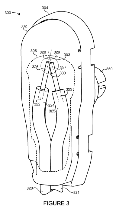
[0062] Figure 3 depicts one example of an EO radiation collector 300. In the
Figure
3 example, the EO radiation collector 300 houses two EO conductor cables, a
first EO
conductor cable 320 and a second EO conductor cable 321. Each of the EO
conductor
cables 320 and 321 may comprise EO conductors 322 and 323 (e.g., fiber optic
cables)
within respective sheaths 324 and 325, which may be opaque to EO radiation
(e.g.,
may be non-electro-optically conductive). As shown in Figure 3, the sheathing
324 and
325 may be removed at respective end portions of the EO cables 320 and 321 to
expose portions 326 and 327 of the EO conductors 322 and 323. The exposed
portions 326 and 327 of the EO conductor cables 320 and 321 may allow EO
radiation
to be received thereby. EO radiation received by the exposed portions 326
and/or 327
may be transmitted within the EO conductor cables 320 and 321.
[0063] The exposed portions 326 and 327 may be secured within the EO radiation
collector 300 at a particular orientation with respect to one another.
However,
alternative configurations and placements of the EO conductor cables 320 and
321 are
possible through modification to the EO radiation collector 300 (e.g.,
modifications to
the cap 302, the base portion 304, and the like).
[0064] In some embodiments, and as illustrated in Figure 3, the EO conductor
cables 320, 322 may be mounted within the EO radiation collector 300, such
that the
longitudinal axis 328 of the first EO conductor cable 320 is non-parallel with
respect to
the longitudinal axis 329 of the second EO conductor cable 321. The
orientation of the
longitudinal axes 328 and 329 may provide and/or facilitate EO transmission
between
the EO conductor cables 320 and 321. The EO transmission path electro-
optically
coupling the EO conductor cables 320 and 322, may allow EO radiation emitted
from
the first EO conductor cable 320 (via the exposed portion 326 thereof) to be
received by
the second EO conductor cable 321 (via the exposed portion 327), and vice
versa. In
some embodiments, and as shown in Figure 3, the longitudinal axes 328 and 329
may
intersect in 2D or 3D space.
[0065] In some embodiments, the EO transmission path between the EO conductor
cables 320 and 321 may include the cap 302. Accordingly, the cap 302 may be
configured to transmit EO radiation between the exposed portions 326 and 327
of the
EO conductor cables 320 and 322. For example, the cap 302 may include material
configured to diffuse EO radiation. Accordingly, a portion of EO radiation
emitted from
the exposed end 326 of the first EO conductor cable 320 may be diffused within
the cap
14
CA 02736033 2011-03-03
WO 2010/033851 PCT/US2009/057548
302 material and received by the exposed end 327 of the second EO conductor
cable
321. In some embodiments, an inner surface of the cap 302 may be treated with
a
reflective material and/or a material having refractive properties configured
to direct EO
radiation between the EO conductors 320 and 321. Alternatively, or in
addition, the cap
302 may comprise reflective portions configured to reflect EO radiation
between the
portions 326 and 327. For example, the cap 302 may include a substantially
smooth
inner surface (not shown), which may be configured to direct EO radiation
between the
exposed portions 326 and 327 (e.g., a surface proximate to the exposed ends
326 and
327 of the EO conductor cables 320 and 321). One example of such a surface is
described below in conjunction with Figure 4B.
[0066] In some embodiments, the cap 302 may be configured to emit a portion of
EO radiation received via the first and/or second EO conductor cables 320
and/or 321.
Accordingly, when EO radiation is emitted into the EO radiation collector 300
via the
exposed portion 326 of the first EO conductor cable 320 and/or the exposed
portion
327 of the second EO conductor cable 321, a portion of the EO radiation may be
emitted from the cap 302. If the EO radiation is in the visible spectrum, the
emitted EO
radiation may be visible by a human and/or detected by other EO radiation
detection
devices. The emission may allow a user (or other device) to confirm that EO
radiation
has been received by the EO radiation collector 300 (e.g., transmitted to the
EO
radiation collector 300 via the first and/or second EO conductor cable(s) 320
and/or
321).
[0067] As shown in Figure 3, the ends of the exposed portions 326 and 327 may
be
secured at substantially the same location within in the cap 302 (e.g., at the
same
vertical offset within the cap 302). Accordingly, the exposed portions 326 and
327 may
both be secured within an EO radiation receiving area 303 (discussed below).
[0068] In some embodiments, the exposed portions 326 and 327 may be in contact
with one another at a contact location 330. The exposed portions 326 and/or
327 may
be adapted to increase a contact area therebetween. For example, ends of the
exposed portions 326 and 327 may be adapted (filed down) to increase the
contact
area therebetween (e.g., to create a contact plane between the portions 326
and 327 at
the location 330). Although not shown in Figure 3, in some embodiments, the
ends of
the exposed portions 326 and 327 may be secured in contact using a securing
member, such as a clamping device, a clip, resilient member, adhesives, or the
like.
CA 02736033 2011-03-03
WO 2010/033851 PCT/US2009/057548
[0069] As discussed above, the cap 302 may be formed of materials adapted to
transmit EO radiation. Accordingly, incident EO radiation emitted in the
vicinity of the
EO radiation collector 300 may be transmitted through the cap portion 302 and
into the
exposed portions 326 and 327 of the EO conductor cables 320 and 321.
[0070] In some embodiments, the cap 302 may be configured to direct (e.g.,
focus)
incident EO radiation (e.g., EO radiation emitted in the vicinity of the EO
radiation
collector) into an EO radiation receiving area 303. For example, the cap 302
may
include portions of varying thickness and/or comprised of materials having
different
reflective and/or refractive properties, which may cause incident EO radiation
to be
directed to a particular location within the EO radiation collector 300. In
the Figure 3
example, the cap 302 is configured to cause incident EO radiation to be
focused into
the EO radiation receiving area 303. The nature (e.g., size, orientation,
etc.) of the EO
radiation receiving area 303 may be determined by the configuration of the cap
302
and/or other elements of the EO radiation collector 300 (e.g., additional
lenses,
surfaces, and the like). As described above, the cap 302 may include materials
having
differing thicknesses and/or of differing optical qualities, which may cause
EO radiation
to be directed to different locations within the EO radiation collector 300.
In the Figure
3 embodiment, the EO radiation collector 300 is configured to secure both of
the
exposed portions 326 and 327 of the EO conductor cables 320 and 321 the EO
radiation receiving area 303. Accordingly, both the EO conductor cables 320
and 321
may be ideally situated within the EO receiving area 303 of the EO radiation
collector
300 to receive incident EO radiation collected by the EO radiation collector
300.
[0071] In some embodiments, the cap 302 may be configured to diffuse EO
radiation. For example, an outer surface of the cap 302 may include a
plurality of
indentations or dimples, which may cause incident EO radiation to be diffused
within
the cap 302. The diffusion may be configured to distribute incident EO
radiation within
the cap 302. The diffusion may allow incident EO radiation received from
various
angles and/or locations relative to the EO radiation collector 300 to be
received at the
EO receiving area 303. For instance, incident EO radiation may be diffused
within the
cap 302 (e.g., by dimples on the surface of the cap 302 and/or the material
comprising
the cap 302), which may cause the cap 302 to emit EO radiation, a portion of
which
may be transmitted into the EO radiation receiving area 303. In some
embodiments,
16
CA 02736033 2011-03-03
WO 2010/033851 PCT/US2009/057548
the diffused EO radiation may be directed to the EO receiving area 303 by
adapting the
thickness and/or refractive properties of the cap 302 material as described
above.
[0072] Figure 4A is an exploded view of another embodiment of an EO radiation
collector 400. A cap 402 may be detached from a base portion 404 and a
mounting
portion 450 of the EO radiation collector 400. In the Figure 4 example, the EO
conductor cables 420 and 421 are depicted as if secured within the EO
radiation
collector 400. As illustrated, the exposed ends 426 and 427 of the EO
conductor
cables 420 and 421 may be mounted such that the longitudinal axes thereof (428
and
429) are non-parallel with respect to one another. In addition, in some
embodiments,
the longitudinal axes 428 and 429 may be intersecting (e.g., on a 2D plane
and/or in 3D
space).
[0073] The manufacture and configuration of an EO radiation collector 400
(e.g., the
housing 402, base portion 404, and the like) may be according to various
configurations
and materials as are known in the art. According to some embodiments, the cap
402
and the base portion 404 may be formed from electrically non-conductive
materials.
The EO radiation collector 400 may be modified for a particular application in
which
specific materials, sizes, or configurations are desired. The EO radiation
collector 400,
comprising the base 404 and the cap 402, may be manufactured as one piece or
as
two or more separable and/or inseparable pieces.
[0074] In some embodiments, the cap 402 may be secured to the base portion 404
by a fastening means, such as a weld, adhesive, fusing, snaps, clips,
resilient
members, cement, zip ties, and/or other fastening means known in the art. In
the
Figure 4 example, the cap 402 includes protruding clips 445 configured to mate
with
clip receivers 440 in the base portion 404. Insertion of the clips 445 into
the receiver
440 may secure the cap onto the base portion 404.
[0075] The EO radiation collector 400 may include means for securing one or
more
EO conductor cables (e.g., cables 420 and/or 421). The securing means may
include
any means for securing EO conductor cables known in the art including, but not
limited
to: adhesives, glue, clips, resilient members, gripping members, resilient
teeth,
clamping mechanisms, clamping members, zip ties, or the like. In the Figure 4A
example, the base portion 404 includes a gripping member 425 configured to
secure
the EO conductor cables 420 and 421 within the EO radiation collector 400. The
gripping member 425 may comprise a plurality of resiliently deformable teeth
adapted
17
CA 02736033 2011-03-03
WO 2010/033851 PCT/US2009/057548
to frictionally engage and secure the EO conductor cables 420 and/or 421.
Although
not shown in Figure 4, an additional member (an independent component and/or
formed as part of the base portion 404 and/or cap portion 402) may be adapted
to
position the exposed ends 426 and/or 427 in a particular orientation within
the EO
radiation collector (e.g., provide the bend 430 in the EO conductor cables 420
and 421
depicted in Figure 4A). The additional member may be a protrusion, grooves, or
any
other means for positioning the EO conductor cables 420 and/or 421 in a
particular
orientation.
[0076] The EO collector 400 may include a mounting portion 450 to secure the
EO
radiation collector 400 onto a particular type of surface (e.g., within a
switchgear
enclosure or housing). Depending on the desired mounting surface, a wide
variety of
conceivable features 450 may be used, such as an adhesive patch, a bolt
receiver, one
or more clips adapted to be received by a clip receiver, or the like.
[0077] As illustrated in Figure 4A, the EO radiation collector 400 may receive
two
EO conductor cables 420 and 421, which may enter the EO radiation collector
400 from
a bottom portion of the cap 402 and/or base portion 404. According to
alternative
embodiments, the EO radiation collector 400 may be adapted to receive any
number of
EO conductor cables of various types. Additionally, the EO radiation collector
may be
adapted to receive the EO conductor cables from the sides, top, bottom, and/or
a
combination thereof. Moreover, means for receiving the EO conductor cables
(e.g., the
cable entrances and securing means) may be configured to allow one EO
conductor
cable to be removed while other cable(s) within the EO radiation collector 400
remain
fixedly secured. As previously discussed, according to various embodiments,
the
plurality of cables entering the EO radiation collector 400 may be oriented
and/or bent,
such that the longitudinal axes of each of the cables are not parallel with
one another,
that the exposed portions of the EO conductor cables are within a receiving
area of the
EO radiation collector (e.g., the EO radiation receiving area 303 of Figure
3), the ends
of the exposed portions of the EO conductor cables therein are at
substantially the
same height and/or position as one another, and/or EO radiation transmitted
from one
of the EO conductor cables may be received by one or more of the other EO
conductor
cables and/or emitted from the cap 402.
[0078] As discussed above, portions of an outer surface 405 of the cap 402 may
comprise indentations and/or dimples configured to diffuse incident EO
radiation within
18
CA 02736033 2011-03-03
WO 2010/033851 PCT/US2009/057548
the cap 402. The dimples may be adapted to diffuse EO radiation indicative of
an arc
flash event (e.g., EO radiation having a wavelength and/or intensity typically
produced
in arc flash events). The dimples may cover the entire outer surface 405 of
the cap 402
or only a portion thereof (in a periphery region 406). For example, in some
embodiments, the dimples on the cap 402 may be primarily disposed on the
surface of
a periphery region 406 of the cap 402. As shown in Figure 4A, the periphery
region
406 may include a top-rear region and/or side regions of the cap 402.
Accordingly, the
periphery region 406 may receive incident EO radiation emitted from behind
and/or the
side of the EO radiation collector 400. The incident angle of the EO radiation
so
received may make it difficult to direct the incident EO radiation towards the
exposed
ends 426 and 427 of the EO conductor cables 420 and 421. The diffusion
provided by
the dimpling on the surface 405 and/or within the periphery region 406 may
allow for
EO radiation to be received by the exposed portions 426 and 427.
[0079] Figure 4B depicts another embodiment of an EO radiation collector cap.
Figure 4B provides a view of an inner portion of the cap 402. As discussed
above, the
material comprising the cap 402 may have a thickness profile 407 configured to
direct
incident EO radiation into a receiving area 403. As shown in Figure 4B, the
exposed
portions 426 and 427 of the EO conductor cables 420 and 421 may both be
secured
within the EO radiation receiving area 403.
[0080] The EO conductor cables 420 and 421 may be secured at a particular
orientation within the cap 402 by an indentation 409 therein. The indentation
409
(along with the protrusion 413) may be configured to maintain the EO conductor
cables
420 and 421 in the non-parallel-axis orientation described above. In the
Figure 4B
example, the EO conductor cables are secured within indentation 409 by clip
members
410 and 411. The clip members 410 may be configured to frictionally engage the
EO
conductor cables 420 and 421 as they enter the cap 402. The clip members 411
may
be configured to frictionally engage the EO conductor cables 420 and 421 to
the
protrusion 413. The protrusion 413 may be adapted to orient the EO conductor
cables
420 and 421 in the non-parallel-axis orientation described above. The cap 402
of Figure
4B may be secured to a base portion (not shown) by protruding clip members
445.
[0081] As discussed above, in some embodiments, the cap 402 may be configured
to diffuse incident EO radiation. The diffusion may be provided by the
material 407
19
CA 02736033 2011-03-03
WO 2010/033851 PCT/US2009/057548
comprising the cap 402 and/or by features (e.g., indentations and/or dimples)
disposed
on an outer surface 405 of the cap 402.
[0082] In some embodiments, the material 407 from which the cap 402 is formed
may be configured to direct incident EO radiation into the EO receiving area
403. The
incident EO radiation may be directed by adapting the thickness profile of the
material
407 and/or selecting different material configurations (e.g., materials having
different
refractive properties).
[0083] As discussed above, EO radiation emitted from one of the EO conductor
cables 420 and/or 421 may be received by the other EO conductor cables 421
and/or
420. Accordingly, an EO transmission path may exist between the EO conductor
cables 420 and 421. The EO transmission path may be provided by the
orientation of
the EO conductor cables 420 and 421 (e.g., in a non-parallel axis
orientation). In some
embodiments, EO radiation may be transmitted between the EO conductor cables
420
and 421 via the cap 402 (e.g., the cap 402 may provide a portion of the EO
transmission path). In some embodiments, a portion of the inner surface of the
cap 402
(portion 415) may be configured to be reflective. Accordingly, a portion of EO
radiation
emitted from the EO conductor 420 and/or 421 may be reflected into the other
EO
conductor 421 and/or 420. The reflective properties of the surface portion 415
may be
provided by smoothing the surface portion 415, depositing a layer of
reflective material
on the surface portion 415, or the like. Inner side portions 417 of the cap
may be
similarly treated. The reflective treatment applied to the inner portion 415
and/or 417 of
the cap 402 may be configured to allow the portions 415 and/or 417 to transmit
incident
EO radiation to the exposed portions 426 and 427 (e.g., the reflection may be
substantially one-way, such that incident EO radiation is not reflected out of
the cap
402).
[0084] Figure 5 provides an exemplary block diagram of an arc flash detection
device having an EO radiation collector. The apparatus 500 may be capable of
performing a self-test to validate the proper operation and/or configuration
of the EO
radiation collectors connected thereto (e.g., the EO radiation collector 513)
and/or the
electro-optical connection between the EO radiation collector 513 and the
apparatus
500 (e.g., the EO conductor cables 510 and 511).
[0085] As shown in Figure 5, the EO radiation collector 513 may be similar to
the EO
radiation collectors 300 and/or 400 disclosed above in conjunction with
Figures 3, 4A,
CA 02736033 2011-03-03
WO 2010/033851 PCT/US2009/057548
and 4B. The apparatus 500 may include an arc flash detection unit 503, which
may be
implemented similarly to the AFDU 103 and/or 203 disclosed above in
conjunction with
Figures 1A, 1 B, and/or 2. The AFDU 503, or portions thereof, may be
implemented
within an IED 502. Alternatively, the AFDU 503 may be implemented
independently of
the IED 502.
[0086] The AFDU 503 and/or IED 502 may be communicatively coupled to the EO
radiation collector 513 by EO conductor cables 510 and 511. The EO conductor
cables
510 and 511 may include an EO conductor sheathed in a non-EO conductive
sheathing. End portions 526 and 527 of the EO conductor cables 510 and 511 may
be
secured within the EO radiation collector 513 as described above (e.g., may be
secured
so that their longitudinal axes are non-parallel with respect to one another
and/or so
that exposed portions 526 and 527 thereof are within an EO radiation receiving
area).
In some embodiments, ends of the EO conductor cables 510 and 511 may be in
contact.
[0087] According to the illustrated embodiment, the IED 502 and/or the AFDU
503
may include a processor 541 (which may be a microprocessor, field programmable
gate
array (FPGA), application specific integrated circuit (ASIC), or the like) and
computer-
readable storage media 543 (e.g., disk storage, optical storage, Flash memory,
RAM,
or the like). The AFDU 503 may use the processor and/or storage media 543 to
provide arc flash monitoring and protection functionality, including self-
test. The
computer-executable instructions for the self-test functions may be stored
within the
storage media 543. The self-test may be configured to automatically operate on
a
scheduled basis (for example, every four hours), continuously, and/or operate
when a
command is received via a human-machine interface (not shown), communications
link
or interface 545, or the like.
[0088] The orientation of the EO conductor cables 510 and 511 within the EO
radiation collector 513 may allow EO radiation to be transmitted therebetween.
Accordingly, EO radiation emitted from the end 526 of the EO conductor cable
510 may
be received by the end 527 of the EO conductor cable 511 and vice versa. In
some
embodiments, the EO radiation collector 513 may be configured to provide an EO
transmission path between the exposed portions 526 and 527 of the EO conductor
cables 510 and 511. The EO transmission path may be enabled by the non-
parallel
orientation of the exposed portions 526 and 527 within the EO radiation
collector 513.
21
CA 02736033 2011-03-03
WO 2010/033851 PCT/US2009/057548
For example, a cap 515 (or other components) of the EO radiation collector 513
may be
configured to transmit EO radiation between the exposed portions 526 and 527
of the
EO conductor cables 510 and 511. The cap 515 may be comprised of materials
configured to refract and/or reflect EO radiation between the cables 510 and
511. In
addition, portions of an inner surface of the cap 515 may include reflective
portions
(e.g., the reflective surface 415 and/or 417 of Figure 4B) configured to
reflect EO
radiation between the exposed portions 526 and 527.
[0089] In some embodiments, a self-test may comprise causing an EO emitter 519
to emit EO radiation into the first EO conductor cable 510. The EO emitter 519
may
comprise any EO radiation source known in the art, including, but not limited
to: a flash
bulb, a light emitting diode (LED), or the like. If the EO conductor cable 510
is
functioning properly, EO radiation produced by the EO emitter 519 may be
transmitted
to the EO radiation collector 513 by the EO conductor cable 510. The EO
radiation
may be emitted into the EO radiation collector 513 via the exposed portion 526
of the
EO conductor cable 510. The EO radiation emitted into the EO radiation
collector 513
may be transmitted into the second EO conductor cable 511 via the exposed
portion
527 (e.g., via the EO transmission path described above).
[0090] The EO radiation collector 513 may be configured to emit a portion of
the
received EO radiation, allowing a human observer (or other detection means) to
detect
the EO radiation received thereby (e.g., to verify that the EO conductor cable
510 is
capable of transmitting EO radiation into the EO radiation collector 513).
[0091] If the EO radiation collector 513 is operating properly and/or is
properly
configured (e.g., the exposed portions 526 and 527 are properly oriented
within the EO
radiation collector 513 and the like), EO radiation transmitted into the EO
radiation
collector 513 via EO conductor cable 510 may be received by the second EO
conductor
cable 511 and transmitted to the EO sensor 521. The EO sensor 521 may be
configured to convert the received EO radiation into a signal (e.g. current
and/or voltage
signal), which, as discussed above, may be filtered, amplified, and/or
quantized (e.g.,
by an A/D converter). The resulting signal may then be received by the AFDU
503
and/or processor 541, which may validate the operation and/or configuration of
the EO
radiation collector 513 and/or the EO conductor cables 510 and 511.
[0092] In some embodiments, if an EO signal is emitted from the EO emitter
519,
but no EO signal is received by the EO sensor 521 (or the signal is below an
22
CA 02736033 2011-03-03
WO 2010/033851 PCT/US2009/057548
attenuation threshold), the AFDU 503 and/or IED 502 may detect a self-test
failure. In
response to detecting a self-test failure, the AFDU 503 and/or the IED 502 may
take
one or more actions including, but not limited to: asserting one or more
alarms,
transmitting one or more alert signals (e.g., via the communications interface
545),
tripping one or more breakers, or the like. The alarms and/or alerts may be
presented
on a human-machine interface 560 (e.g., via audio queues, visual indications,
or the
Iike).
[0093] If EO radiation is detected by the EO sensor 521 (and has an intensity
above
a threshold), the AFDU 503 and/or IED 502 may detect a self-test pass. The
self-test
may further comprise determining an attenuation of the EO radiation as it is
transmitted
through the first EO conductor cable 510, the EO radiation collector 513, and
the
second EO conductor cable 511. If the attenuation exceeds a threshold, the
self-test
operation may fail; otherwise, the self-test may pass. The attenuation may be
displayed on the human-machine interface 560, may be transmitted on a
communications interface 545, or the like.
[0094] In some embodiments, the AFDU 503 and/or IED 502 may be configured to
stop arc flash monitoring during a self-test operation. Alternatively, or in
addition, the
AFDU 503 and/or the IED 502 may be configured to distinguish between EO
radiation
received as part of a self-test operation and EO radiation indicative of an
arc flash
event. For instance, in some embodiments, the AFDU 503 and/or the IED 502 may
be
configured to cause the EO emitter 519 to emit EO radiation according to a
particular
pattern. The pattern may comprise a low-correlation coded signal or waveform.
During
a self-test operation, the EO sensor 521 may receive return signals indicative
of the
coded signal. Accordingly, the AFDU 503 and/or IED 502 may be capable of
distinguishing between EO radiation indicative of an arc flash event and EO
radiation
received as part of a self-test, which may allow the apparatus 500 to perform
self-
testing while simultaneously providing arc flash monitoring and/or protection.
The
simultaneous self-test and/or monitoring may be provided independently of the
nature
of the EO radiation emitted by the EO emitter 519. Accordingly, the EO
radiation
pattern emitted by the EO emitter 519 may be of the same wavelength,
frequency,
and/or intensity as would be produced in an arc flash event. As such, the self-
test may
be capable of validating the EO radiation collector 513 and/or EO conductor
cables 510
and 511 within the parameters (e.g., frequency, wavelength, and/or intensity)
of an
23
CA 02736033 2011-03-03
WO 2010/033851 PCT/US2009/057548
actual arc-flash event. Alternatively, or in addition, the EO emitter 519 may
be
configured to emit EO radiation of a different frequency and/or wavelength
than that
produced during an arc flash event. The resulting EO signals may be
distinguished by
the AFDU 503 and/or IED 502 to prevent false arc flash detections.
[0095] In some embodiments, a self-test operation may determine where a self-
test
failure has occurred (or reduce the search space for the failure point). As
discussed
above, the EO radiation collector 513 may be configured to emit EO radiation
received
via an EO cable 510 and/or 511 (e.g., via the cap 515). An additional sensing
device
(not shown), such as a human observer (or additional EO radiation collector
(not
shown)) may be placed within an EO path of the EO radiation collector 513 to
detect
EO radiation emitted thereby. If, during a self-test, EO radiation is detected
from the EO
radiation collector 513, but no return signal is received via the EO conductor
cable 511,
the IED 502 and/or AFDU 503 may determine that the EO conductor cable used to
transmit the EO signal to the EO radiation collector 513 (e.g., EO conductor
cable 510)
is operable, but that a fault exists within the EO radiation collector 513
and/or in the EO
conductor cable 511. The self-test may switch the EO conductor cables and re-
run the
self-test (e.g., connect the EO emitter 519 to the EO conductor cable 511 and
the EO
sensor 521 to the EO conductor cable 510). The switch may be made via an EO
switching device (not shown), modification of physical connections, or the
like. If, after
the switch, the EO radiation collector 513 emits EO radiation during the self-
test, the
fault may be determined to be in the EO radiation collector itself 513 (since
the other
EO conductor cable, cable 511, has transmitted EO radiation to the EO
radiation
collector 513). If the EO radiation collector 513 does not emit EO radiation
after the
switch, the fault may be determined to be in the EO conductor cable 511.
Although a
particular self-test scenario is described herein, the disclosure is not
limited in this
regard. The AFDU 503 and/or the IED 502 may be configured to perform any self-
test
and/or adaptive self-test known in the art.
[0096] The status of the self-test operations performed by the IED 502 and/or
AFDU
503 may be displayed on an HMI 560 and/or communicated via a communications
interface 545. Alternatively, or in addition, the results of the self-test
operations may be
stored on the computer-readable storage media 543. The results may be made
available to personnel via the HMI 560 or other interface (e.g., interface
545). The
display and/or results of the self-test may include the attenuation (if any)
observed
24
CA 02736033 2011-03-03
WO 2010/033851 PCT/US2009/057548
during the test (e.g., a difference between the intensity of EO radiation
transmitted into
the EO radiation collector 513 versus the intensity of the EO radiation
received by the
EO sensor 521), the response time of the AFDU 503 and/or IED 502 to detect the
return signal, a probable location of the failure (if any), or the like.
[0097] As discussed above, EO radiation transmitted into the EO radiation
collector
513 (e.g., via the EO conductor cable 510) may illuminate portions of the
collector 513,
such as the cap 515. The illumination may be used for diagnostics, testing,
and/or
maintenance of the system 500. For instance, in some embodiments, the AFDU 503
and/or IED 502 may be configured to emit visible EO radiation into the EO
radiation
collector 513 responsive to detecting EO radiation at a particular threshold
therefrom.
The threshold may be selected to exceed the ambient EO radiation levels to
which the
EO radiation collector 513 is typically exposed. In some embodiments, the
threshold
may include an upper bound to prevent the EO emitter 519 from operating during
an
arc flash event. The emitted EO radiation may illuminate the EO radiation
collector
513, thereby providing a visual confirmation that the EO radiation collector
513 is
operating properly (e.g., is capable of collecting EO radiation, transmitting
the collected
EO radiation to the EO sensor 521, and receiving EO radiation from the EO
emitter
519).
[0098] In one example, an EO radiation emitter 580 may be used to emit EO
radiation
into the EO radiation collector 513. The EO radiation emitter 580 may comprise
a
flashlight, an LED, flashbulb, incandescent light source, fluorescent light
source, or any
other device capable of emitting EO radiation. The EO radiation emitter 580
may be
operated by a human, by the ADFU 503 and/or IDE 502, and/or some other device
(e.g., a dedicated testing and validation device (not shown)). As discussed
above, a
portion of the EO radiation emitted by the EO radiation emitter 580 may be
collected by
the EO radiation collector 513 and transmitted to the EO sensor 521 via the EO
conductor cable 511. Responsive to detecting the EO radiation, the AFDU 503
and/or
IED 502 may cause the EO emitter 519 to emit visible EO radiation into the EO
conductor cable 510. The emitted EO radiation may illuminate the EO radiation
collector 513 with visible light, which may provide a visual confirmation that
the EO
radiation collector 513 is functioning properly (e.g., the EO radiation
collector 513 may
"glow" red). In some embodiments, the EO radiation emitter 580 may further
include an
CA 02736033 2011-03-03
WO 2010/033851 PCT/US2009/057548
EO sensor (not shown), which may provide for automated detection of EO
radiation
emitted from the EO radiation collector 513.
[0099] Figure 6 illustrates one embodiment of a system 600 comprising a
plurality of
electro-optically coupled EO radiation collectors 602, 604, 606, 608. The EO
radiation
collectors 602, 604, 606, and 608 may be electro-optically coupled to an IED
502
and/or AFDU 503.
[00100] The EO radiation collectors 602, 604, 606, and 608 may be electro-
optically
connected in a series arrangement (daisy chain) using EO transmission cables
610,
612, 614, 616, and 618. Although a daisy chain arrangement is shown herein,
the
disclosure is not limited in this regard. In other embodiments, EO radiation
collectors
(such as the EO radiation collectors 602, 604, 606, and/or 608) could be
arranged in a
web pattern, a branching arrangement, in a graph, or other formation. The
alternative
configurations may include the use of more than two EO conductor cables in a
particular EO radiation collector, the use of branching EO conductor cables,
EO
radiation repeaters, or the like.
[00101] In the Figure 6 example, the EO conductor cable 610 is in electro-
optical
communication with an EO emitter 519 and the EO radiation collector 602. The
EO
conductor cable 612 electro-optically connects the EO radiation collector 602
to the EO
radiation collector 604, which is electro-optically coupled to the EO
radiation collector
606 by the EO conductor cable 614, which is electro-optically coupled to the
EO
conductor 608 via the EO conductor cable 616. The EO radiation collector 608
is
electro-optically coupled to the EO sensor 521 via the EO conductor cable 618.
[00102] The EO radiation collectors 602, 604, 606, and/or 608 may be
configured to
provide an EO transmission path between the EO conductor cables received
therein
(e.g., the EO conductor cables 610 and 612 may be electro-optically coupled
within the
EO radiation collector 602, the EO conductor cables 612 and 612 may be electro-
optically coupled within the EO radiation collector 604, and so on). As
described
above, the transmission of EO radiation between the EO conductor cables within
the
EO radiation collectors 602, 604, 606, and/or 608 may be enabled by an
orientation in
which the EO conductors are secured therein (non-parallel longitudinal axis
orientation),
by the configuration of the EO radiation collectors 602, 604, 606, and/or 608
(e.g.,
properties of a cap portion of the EO radiation collectors 602, 604, 606,
and/or 608),
and the like.
26
CA 02736033 2011-03-03
WO 2010/033851 PCT/US2009/057548
[00103] In a self-test operation, EO radiation emitted by the EO emitter 519
may be
transmitted into the EO conductor cable 610 to be received at the EO radiation
collector
602. The EO radiation received at the EO radiation collector 602 may be
transmitted
into the EO conductor cable 612 (via the EO transmission path provided by the
EO
radiation collector 602) to the EO radiation collector 604, which, in turn,
may be
transmitted to the EO radiation collectors 606 and 608 as described above. The
emitted EO radiation received at the EO radiation collector 608 may be
transmitted to
the EO sensor 521 via the EO conductor cable 618. The EO sensor 521 may detect
the emitted EO radiation returning from the EO radiation collector 608. The
AFDU 503
and/or IED 502 may use the detected EO radiation corresponding to the emitted
EO
radiation to determine a result of the self-test operation. If EO radiation
corresponding
to the emitted EO radiation is received by the EO sensor 521 (and has not been
attenuated beyond a threshold), the self-test operation may pass. If no EO
radiation is
returned and/or if the returning EO radiation has been attenuated more than a
threshold
amount, the result of the self-test operation may be a failure.
[00104] The location of a self-test failure may be isolated by detecting EO
radiation
emitted from the EO radiation collectors 602, 604, 606, and/or 608 during a
self-test
operation. As discussed above, the EO radiation collectors disclosed herein
may be
configured to emit EO radiation when EO radiation is received via an EO
conductor
cable (e.g., emitted from a cap of the EO radiation collector). During a self-
test, EO
radiation may be emitted from each of the EO radiation collectors 602, 604,
606, and/or
608 that the emitted EO radiation has reached. If EO radiation does not reach
a
particular EO radiation collector (602, 504, 606, or 608), a location of the
fault
preventing EO radiation from reaching the collector may be isolated. For
example, if
emitted EO radiation illuminates the EO radiation collectors 602 and 604, but
not 606 or
608, it may be determined that a fault exists in the EO radiation collector
604 and/or in
the EO conductor cable 614, since the fault presumably does not exist in the
EO
conductor cables 610 and/or 602 since the EO radiation collectors 602 and 604
are
receiving the emitted EO radiation.
[00105] In some embodiments, a second set of one or more EO radiation
collectors
(not shown) may be configured to receive EO radiation emitted from the EO
radiation
collectors 602, 604, 606, and/or 608. The EO radiation detected by the second
set of
EO radiation collectors may be used to isolate the location of the cause of a
self-test
27
CA 02736033 2011-03-03
WO 2010/033851 PCT/US2009/057548
failure. In some embodiments, the second set of EO radiation collectors may be
configured to determine an attenuation of the emitted EO radiation signal as
it flows
between the EO radiation collectors 602, 604, 606, and/or 608. The location of
the
cause of a self-test failure may correspond to high-levels of attenuation
(e.g., high-level
of attenuation may exist between the EO radiation collectors 602 and 604,
which may
indicate that the EO conductor cable 612 is not operating properly).
[00106] Alternatively, or in addition, a technician (or other human) may
observe the
EO radiation emitted from the EO radiation collectors 602, 604, 606, and/or
608 during
a self-test operation to visually identify a probable location of the cause of
a self-test
failure. As discussed above, the AFDU 503 and/or IED 502 may be configured to
cause the EO emitter 519 to illuminate the EO radiation collectors 602, 604,
606, and/or
608 responsive to detecting EO radiation at the EO sensor 521 (e.g., from a
flashlight
or other EO radiation emitter (not shown)). The illumination may provide a
visual
confirmation that the EO radiation collectors 602, 604, 606, and/or 608 are
functioning
properly.
[00107] Figure 7 depicts another example of a device for detecting an arc
flash event
using an EO radiation collector. In the example 700, the AFDU 503 and/or IED
503
includes an EO switch component 770, which may be configured to selectively,
electro-
optically couple the EO conductor 610 to the EO emitter 519 and/or the EO
sensor 521.
The EO switch 770 may be configured to electro-optically couple to the EO
emitter 519
to the EO conductor 610 during a self-test operation. When so configured, the
EO
conductor 610 may receive EO radiation emitted by the EO emitter 519. When
self-
testing is not being performed, the EO switch 770 may be configured to electro-
optically
couple the EO conductor 610 to the EO sensor 521. In this configuration, EO
radiation
collected by the EO radiation collectors 602, 604, 606, and/or 608 and
transmitted
through the EO conductors (612 and/or 614) may be received by the EO sensor
521 via
the EO conductor 610. As such, EO radiation indicative of an arc flash event
may be
received by the EO sensor 521 via redundant electro-optical paths.
Accordingly, even if
one or more of the EO conductor cables 612, 614, and/or 618 fails (is
incapable of
transmitting EO radiation), EO radiation may be received via the alternative
path
provided by the electro-optical coupling of the EO conductor cable 610 to the
EO
sensor 521.
28
CA 02736033 2011-03-03
WO 2010/033851 PCT/US2009/057548
[00108] In alternative embodiments, the EO switch 770 may be replaced by other
electro-optical elements, such as splitters, electro-optical elements
configured to
transmit EO radiation into the EO conductor 610 while isolating the EO sensor
521 from
the emitted EO radiation, or the like. Accordingly, the disclosure should not
be read as
limited to the use of any particular EO switching element or mechanism.
[00109] In some embodiments, an additional EO switching element (not shown)
may
be provided between the EO sensor 521 and the EO conductor cable 618. The
additional switching element may be used to direct EO radiation emitted by the
EO
emitter 519 into the EO conductor 618, which may allow the "order" of a self-
test
operation to be reversed (e.g., reverse the flow of EO radiation through the
collectors
602, 604, 606 and/or 608 during a self-test operation). As discussed above,
reversing
the flow of a self-test operation may be used to isolate the cause of a self-
test failure.
[00110] In another variation, the EO emitter 519 and EO sensor 521 elements
may be
replaced by an EO transceiver element, which may be electro-optically coupled
to both
the EO conductors 610 and 618. The EO transceiver may be configured to emit
and
sense EO radiation on either of the EO conductor cables 610 and/or 618.
[00111] Although the AFDU 503 and IED 502 is depicted as electro-optically
coupled
to a plurality of EO radiation collectors 602, 604, 606, and 608 in a daisy
chain
arrangement, the example 700 could be modified to include only a single EO
radiation
collector, incorporate EO radiation collectors of different types (e.g., loop
EO radiation
collectors), arrange the EO radiation collectors in different configurations,
or the like.
[00112] Additionally, in alternative embodiments of the example 700 (or the
examples
500 and/or 600 described above), the EO radiation collectors 602, 604, 606,
and/or 608
could be modified to include one or more EO radiation amplifiers, EO radiation
repeaters, EO sensors, and the like. In this way, the effects of EO radiation
attenuation
within the daisy chain configuration (or on a long run of an EO conductor
cable) could
be mitigated and/or obviated.
[00113] The above description provides numerous specific details for a
thorough
understanding of the embodiments described herein. However, those of skill in
the art
will recognize that one or more of the specific details may be omitted, or
other methods,
components, or materials may be used. In some cases, operations are not shown
or
described in detail.
29
CA 02736033 2011-03-03
WO 2010/033851 PCT/US2009/057548
[00114] Furthermore, the described features, operations, or characteristics
may be
combined in any suitable manner in one or more embodiments. It will also be
readily
understood that the order of the steps or actions of the methods described in
connection with the embodiments disclosed may be changed as would be apparent
to
those skilled in the art. Thus, any order in the drawings or Detailed
Description is for
illustrative purposes only and is not meant to imply a required order, unless
specified to
require an order.
[00115] Embodiments may include various steps, which may be embodied in
machine-executable instructions to be executed by a general-purpose or special-
purpose computer (or other electronic device). Alternatively, the steps may be
performed by hardware components that include specific logic for performing
the steps,
or by a combination of hardware, software, and/or firmware.
[00116] Embodiments may also be provided as a computer program product
including a computer-readable storage medium having stored instructions
thereon that
may be used to program a computer (or other electronic device) to perform
processes
described herein. The computer-readable storage medium may include, but is not
limited to: hard drives, floppy diskettes, optical disks, CD-ROMs, DVD-ROMs,
ROMs,
RAMs, EPROMs, EEPROMs, magnetic or optical cards, solid-state memory devices,
or
other types of media/machine-readable storage media suitable for storing
electronic
instructions.
[00117] As used herein, a software module or component may include any type of
computer instruction or computer executable code located within a memory
device
and/or computer-readable storage medium. A software module may, for instance,
comprise one or more physical or logical blocks of computer instructions,
which may be
organized as a routine, program, object, component, data structure, etc., that
perform
one or more tasks or implements particular abstract data types.
[00118] In certain embodiments, a particular software module may comprise
disparate instructions stored in different locations of a memory device, which
together
implement the described functionality of the module. Indeed, a module may
comprise a
single instruction or many instructions, and may be distributed over several
different
code segments, among different programs, and across several memory devices.
Some
embodiments may be practiced in a distributed computing environment where
tasks are
performed by a remote processing device linked through a communications
network. In
CA 02736033 2011-03-03
WO 2010/033851 PCT/US2009/057548
a distributed computing environment, software modules may be located in local
and/or
remote memory storage devices. In addition, data being tied or rendered
together in a
database record may be resident in the same memory device, or across several
memory devices, and may be linked together in fields of a record in a database
across
a network.
[00119] It will be understood by those having skill in the art that many
changes may
be made to the details of the above-described embodiments without departing
from the
underlying principles of the invention.
[00120] What is claimed is:
31