Note: Descriptions are shown in the official language in which they were submitted.
CA 02736115 2011-03-29
2
SPECIFICATION
Title: Adaptive Control System for a Sulfur Recovery Process
This invention relates to an apparatus and method for controlling the
combustion of acid gas
containing hydrogen sulfide in sulfur recovery units (Claus plants).
Sulfur is present in natural gas principally as hydrogen sulfide H2S and in
other fossil fuels as sulfur-
containing compounds which are converted to H2S during processing. The H2S is
removed from the
natural gas or refinery gas by means of one of the gas treating processes. The
resulting H2S-
containing acid gas is processed to recover sulfur. The recovery of free
sulfur from gaseous
streams containing hydrogen sulfide has become a valuable procedure in the
petroleum gas
industries. The Claus process is widely used for sulfur recovery from HZS.
Conventional Claus plant
consists of a thermal conversion section, and a few stages of catalytic
conversion section, in series.
Acid gas feed entering sulfur recovery unit consists of H2S and other
uncombustible gases
(nitrogen, CO2) and sometimes, in small amounts, combustible gases. The
combustion in the
thermal section is controlled by adding a controlled amount of air, required
for burning onethird
of the H2S to react with oxygen to produce SO2. The balance of the conversion
is achieved in the
presence of catalyst in the catalytic conversion stages provided via the
reaction of two-thirds of
H2S and S02, to produce sulfur and water. Liquid sulfur is then collected in
sulfur concentrators.
However, not all the amounts of H2S and SO2 react. Some residual amounts
remain in a tail gas.
Very strict requirements to the residual H2S and SO2 make the control of the
Claus reaction a
difficult problem. Unlike the conventional combustion process, which allows
for the use of
different fuel-air ratios, the Claus reaction requires the stoichiometric
values of H2S and air. Most
commonly, the residual H2S is further burned and converted into
environmentally less harmful SO2
and the latter is emitted. For that reason, excess of either H2S or SO2
compared to the
stoichiometric values increases emissions, and only optimal H2S to SO2 ratio
(corresponding to
stoichiometric combustion), which is achieved by proper air-to-acid gas ratio,
provides minimal
SO2 emissions. Conventional control of the Claus reaction includes an air-to-
acid gas ratio
CA 02736115 2011-03-29
3
controller that generates a command for a main air flow controller, which
manipulates a main air
flow valve, and an analyzer controller of proportional-integral-derivative
(PID) type that generates
a command for a trim air flow controller, which manipulates a trim air flow
valve. The set point
(ratio value) for the ratio controller is entered by an operator. The analyzer
controller uses the
measurements of residual H2S and 502 in a tail gas to generate a command for
the trim air flow
controller, so that it generates a command to bring tail gas H2S-to-SO2 ratio
to the set point 2. This
control scheme may provide a satisfactory performance of the control system if
the acid gas flow
is relatively steady. If the acid gas flow fluctuates (which is normally the
case) it becomes very
difficult to achieve a satisfactory performance of the control. As a result,
in many cases a very
expensive additional treatment of the tail gas aimed at removing the residual
H2S and SO2 may be
needed to reduce emissions.
U.S. Pat. Nos. 3,985,864 (1976) of Lucien H. Vautrain, et al. discloses an
automatic control system
for a Claus sulfur plant. The flow rate of the oxygen-containing gas to a
process for the oxidation of
hydrogen sulfide is regulated so as to be responsive to changes in pressure in
the hydrogen sulfide
feedstream. In both patents, the overall ratios of oxygen to hydrogen sulfide
are adjusted to
maintain the desired ratio of hydrogen sulfide to oxygen feed. In carrying out
stoichiometric
control of the hydrogen sulfide gas stream and oxygen-containing gas stream,
there are five
objectives cited. These objectives are (1) maintain the quantity of oxygen
below that
stoichiometrically required for the oxidation of the hydrogen sulfide in order
to prevent the
formation of sulfates; (2) maintain the oxygen quantity as close as possible
to the stoichiometry
required in order to promote the highest possible efficiency of oxidizing the
hydrogen sulfide-
containing gas stream and to reduce the sulfur content of the gaseous effluent
from the process;
(3) maintain stable control of the process while achieving the above two
objectives, even though
the gas flow may vary; (4) maintain stable control, even though the hydrogen
sulfide content of
the hydrogen sulfide gas-containing stream may vary; and (5) effect stable
control of the process
while achieving the above four objectives, even though there is a time between
the occurrence of
a variation in one or both of the process feedstreams and the occurrence of
the measurement of
the effect of that variation on the gaseous effluent from the process. In
summary, both patents
disclose an automated flow control scheme to maintain the required
stoichiometry of the Claus
reaction.
CA 02736115 2011-03-29
4
U.S. Pat. No. RE28,864 of Andral, et al. (with a foreign priority date,
application No. 70.45812 in
France) discloses process and apparatus for automated regulation of sulfur
production units. The
process incorporates oxidation of hydrogen sulfide, in which the flow of gas
carrying oxygen into
the unit is regulated so as to keep an operating parameter, based on
measurement of the
sulfurous compound of the residual gases, level with a reference value. It is
characterized by the
fact that the control signal, used to regulate the flow of gas containing
oxygen at the unit inlet, is a
combination of a signal based on measurements taken at the inlet, and
representing the
theoretical flow of this gas needed to keep the operating parameter at its
reference level and
another signal representing the correction needed in this flow to adjust the
instantaneous value of
the parameter to the reference level. The disclosed process claims better
control of the sulfur unit,
with increased efficiency and reduced atmospheric pollution.
U.S. Pat. No. 4,100,266 of Smith (1978) discloses an automatic control system
for a Claus sulfur
plant, in which control of a process is accomplished by manipulating the flow
rate of a feed stream
containing oxygen to a furnace in such a manner that a desired proportion of
the hydrogen sulfide
fed to the furnace is converted to sulfur dioxide. The flow rate of a feed
stream containing
hydrogen sulfide to a tail gas cleanup process is also manipulated utilizing
feedforward and
feedback control to maintain the hydrogen sulfide and sulfur dioxide
concentrations in the gas
stream from the tail gas cleanup process at acceptable levels.
Some other variations of the described principle were disclosed in U.S. Pat.
5,965,100 of
Khanmamedov (1999), and 7,754,471 of Chen (2010). The described control
principle may provide
a satisfactory performance of the control system if the acid gas flow to the
sulfur recovery process
is a relatively constant value. If the acid gas flow fluctuates (which is
normally the case) it becomes
very difficult to achieve a satisfactory performance of the control. As a
result, in many cases a very
expensive additional treatment of the tail gas aimed at removing the residual
H2S and SO2 is
normally needed. Control performance has a significant effect on the emissions
of environmentally
harmful substances, which can be substantially mitigated by the disclosed
adaptive ratio control.
U.S. Pat. No. 5,176,896 of Bela discloses apparatus and method for generation
of control signal for
Claus process optimization. It incorporates generation of a control signal for
the optimization of
sulfur removal in a Claus process unit that comprises oxidizing a portion of
the tail gas stream
exiting the Claus unit by contacting a portion of the tail gas with an oxygen-
containing gas in the
CA 02736115 2011-03-29
presence of a catalyst which oxidizes H2S to SO2, measuring the temperature
rise associated with
the oxidation reaction, converting the measurement to an appropriate control
signal, and using
the signal to control the rate of air flow into the Claus unit.
Canadian Pat. No. CA 1323173 to Lagas et al. discloses a process for the
recovery of sulfur from a
hydrogen sulfide containing gas (acid gas), which comprises oxidizing hydrogen
sulfide with
oxygen, and then reacting the product gas of this oxidation further by using
at least two catalytic
stages, in accordance with the equation: 2H2S + SO2 = 2H20 + 3/n SR. In order
to improve the
process and the process control, the invention is characterized in that the
H2S concentration in the
gas leaving the last catalytic stage is controlled to have a value ranging
between 0.8 and 3% by
volume by reducing the quantity of combustion or oxidation air passed to the
oxidation stage
and/or causing a portion of the hydrogen sulfide containing feedstock gas to
bypass the oxidation
stage and to be added to the gas flowing to a catalytic stage.
As described, typical control of the Claus reaction includes an air-to-acid
gas ratio controller that
uses measurements of acid gas flow and generates a command for a main air flow
controller,
which in turn manipulates a main air flow valve, and an analyzer controller of
proportional,
integral-derivative (PID) type that uses measurements of H2S and SO2 in a tail
gas and generates a
command for a trim air flow controller, which in turn manipulates a trim air
flow valve. The main
drawback of the available controls is related to possible fluctuations of acid
gas flow and slow
response of the tail gas concentrations to changes in a tail gas flow and air
flow. If a tail gas flow
changes the main air flow controller responds to this change very quickly
incrementing air flow.
However, the air-to-acid gas flow ratio demand is entered by an operator and
is not optimal, so
that the air flow increment would not fully correspond to the acid gas flow
increment, and the
increment of air flow will be either smaller or larger than the optimal
necessary for a
stoichiometric combustion. As a result, after all the reactions occur the
concentrations of H2S and
SO2 in a tail gas will change. Yet, it will only be measured with some delay,
after this reaction has
already happen, which results in insufficiently high quality of control,
observed as high fluctuations
in a tail gas H2S-to-SO2 ratio. Another drawback is related to uncoordinated
motion of the two air
valves, so that one valve may have a command to open, thus increasing air
flow, and the other
valve to have the command to close, thus decreasing air flow, while in fact no
change may be
required in terms of total air required. This uncoordinated motion of the two
air valves contributes
CA 02736115 2011-03-29
6
to the deterioration of the control performance, as the valves respond to
their commands not
instantaneously but with some lag, which differs between the two valves. Those
lags result in the
deviations of the total air flow from the total air flow demand (sum of the
two demands) and
overall performance deterioration.
It would be desirable to calculate and use an optimal value for the air-to-
acid gas ratio demand, so
that any fluctuation in an acid gas flow should be immediately matched by
corresponding amount
of air - through the action of the ratio controller.
The present invention improves performance of the control of the sulfur
recovery process in the
conditions of variable flow rate of acid gas and variable H2S concentration in
acid gas by using an
adaptive ratio control principle. In accordance with an embodiment of this
invention, H2S-to-S02
ratio fluctuations (molar amounts) in the tail gas are substantially reduced
by generating the air
flow demand that is calculated as a sum of the principal air flow demand and
the supplemental air
flow demand, where the principal air flow demand is calculated via
multiplication of the acid gas
flow by the optimal air-to-acid gas ratio demand value, and the supplemental
air flow demand is
calculated by a proportional-integral-derivative (PID) algorithm, with process
variable of the PID
algorithm based on measurements of molar amounts of residual H2S and 502 in
the tail gas. An
optimal value of the air-to-acid gas ratio demand is determined through
learning (adaptation),
which allows for the best possible rejection of disturbances coming to the
control system in the
form of acid gas flow fluctuations, while slow changes in the concentration of
H2S in the acid gas
are compensated for by adaptation aimed at finding a varying optimal value of
the air-to-acid gas
ratio, which changes with changes of H2S concentration. Through this
principle, combustion of
hydrogen sulfide is precisely controlled by the control system to maintain the
hydrogen sulfide and
sulfur dioxide concentrations in the tail gas at the desired ratio and
acceptable levels to minimize
the environmental pollution.
CA 02736115 2011-03-29
7
BRIEF DESCRIPTION OF THE SEVERAL VIEWS OF THE DRAWING
FIG. 1 is an illustration of a Claus sulfur plant with associated controls
(preferred embodiment A);
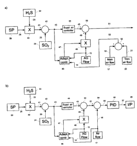
FIG. 2 is a schematic of a processor-based control system means for the
calculation of the principal
air flow demand, supplemental air flow demand and total air flow demand ((a) -
preferred
embodiment A, (b) - preferred embodiment B);
FIG. 3 is a schematic of a processor-based control system means for the
calculation of commands
to main air control valve and trim air control valve for preferred embodiment
A;
FIG. 4 is a schematic of a processor-based control system means of the
adaptive control (preferred
embodiments A and B)
DETAILED DESCRIPTION OF THE INVENTION
The present invention relates to method and apparatus to control the ratio of
air to hydrogen
sulfide (H2S) in the acid gas in Claus (sulfur recovery) reaction. In one
specific aspect the invention
relates to a method and apparatus for obtaining near optimum performance of a
sulfur plant
where free sulfur is produced from hydrogen sulfide. In a second specific
aspect, this invention
relates to a method and apparatus for reducing air pollution produced by the
production of free
sulfur from hydrogen sulfide. In a third specific aspect, the invention
relates to a method and
apparatus for controlling the ratio of hydrogen sulfide to oxygen fed to a
reaction of hydrogen
sulfide and oxygen to form free sulfur. In a fourth specific aspect, the
invention relates to a
method and apparatus for maintaining a desired hydrogen sulfide to sulfur
dioxide ratio in a sulfur
plant tail gas. Other possible applications of the same control principle are
as follows (but not
limited to those): control of fuel combustion in utility boilers by measuring
02 concentration in the
flue gas and manipulating the air flow on the basis of the measurements
obtained; control of SOX
passivation by means of ammonia injection into the gas/liquid; control of
desuperheated steam
temperature in utility boilers by means of spraying water into steam; control
of air-fuel ratio in
internal combustion engines.
Sulfur is present in natural gas principally as H2S and in other fossil fuels
as sulfur-containing
compounds which are converted to H2S during processing. The H2S is removed
from the natural
gas or refinery gas by means of one of the gas treating processes. The
resulting H2S-containing acid
gas is processed to recover sulfur. The recovery of free sulfur from gaseous
streams containing
hydrogen sulfide has become a valuable procedure in the petroleum gas
industries. Such an
operation results in both the recovery of valuable free sulfur and a reduction
of atmospheric
pollution. The Claus process is widely used for sulfur recovery from H2S. The
Claus process as used
CA 02736115 2011-03-29
8
today is a modification of a process first used in 1883 in which H2S was
reacted over a catalyst with
air (oxygen) to form elemental sulfur and water. A modification of the Claus
process was
developed in 1936 in which the overall reaction was separated into a highly
exothermic
combustion reaction section and a moderately exothermic catalytic reaction
section in which
sulfur dioxide formed in the combustion section reacts with unburned H2S to
form elemental
sulfur.
In practice, the control of the reaction is usually implemented with the use
of measurements of
the acid gas flow and the ratio of residual H2S and SO2 in the tail gas after
the reaction, and by
means of two air valves with respective controllers (loops) that utilize the
above measurements.
This control scheme may provide a satisfactory performance of the control
system if the acid gas
flow is a relatively constant value. If the acid gas flow fluctuates (which is
normally the case) it
becomes very difficult to achieve a satisfactory performance of the control.
As a result, in many
cases a very expensive additional treatment of the tail gas aimed at removing
the residual H2S and
502 is normally needed. Control performance has a significant effect on the
emissions of
environmentally harmful substances, and therefore, development of process
model suitable for
controller design and tuning may have a high environmental impact.
In many aspects the Claus process is no different than a regular combustion
process of the fuel gas
in utility boilers, for example. However, very strict requirements to the
residual H2S and S02 make
the control of the Claus reaction a much more difficult problem. Unlike the
conventional
combustion process, which allows for the use of different air-to-fuel ratios,
the Claus reaction
requires the stoichiometric values of H25 and air. Commonly, the residual H2S
is further burned
and converted into environmentally less harmful S02 and the latter is emitted
into the
atmosphere. For that reason, excess of either H2S or S02 compared to the
stoichiometric values
increases emissions, and only optimal H2S to S02 ratio (corresponding to
stoichiometric
combustion) provides minimal SO2 emissions. Another difference that
complicates the control of
the Claus reaction is uncontrolled acid gas flow (all available acid gas must
be incinerated) versus
regulated fuel flow in other types of combustion. The main objective of the
control quality
enhancement is to ensure the conversion of all available H2S into relatively
neutral and
environmentally safe sulfur; increase of sulfur production is usually a
secondary objective only.
The free sulfur generally is produced by a process which involves the
following two reactions. The
reaction in the thermal or combustion reaction section is given by the
following expression (J. B.
Pfeiffer, Sulfur Removal and Recovery from Industrial Processes, Washington,
DC, U.S.A,. American
Chemical Society, 1975):
H2S+1Y02--*S02+H20 (1)
The reaction in the combustion and catalytic reaction sections is given as
follows:
2 H2S + S02 -> 3/x SX + 2 H2O (2)
CA 02736115 2011-03-29
9
If high H2S / 502 conversion levels are to be reached in the Claus reaction,
this ratio should be kept
as close as possible to the stoichiometric value of two.
The first reaction generally takes place in the combustion chamber of a
boiler. Since this reaction is
highly exothermic, the substantial amount of heat which is released is
recovered in the form of
steam production. One third of the source hydrogen sulfide is combined with
air to form sulfur
dioxide in this reaction. The reaction of the hydrogen sulfide is combined
with the reaction
products from the combustion chamber to carry out the second reaction in the
furnace. The
effluent from the furnace is cooled, and the free sulfur product is recovered
as a liquid.
All the hydrogen sulfide and sulfur dioxide gases will not be converted in the
furnace. The
remaining unconverted gases are passed through a catalytic sulfur removal
reactor to further
convert the unreacted hydrogen sulfide and sulfur dioxide to free sulfur. The
effluent from the
reactor is cooled, and the free sulfur product is removed as a liquid.
Let qH2s be the molar amount (flow) of H2S and q02 be the molar amount (flow)
of 02. Then
assuming that all oxygen is reacted in the combustion reaction we can write an
expression for the
molar amount of SO2 obtained as a result:
gl"so2 = 2/3 qo2, (3)
where superscript "1" refers to the combustion reaction. In this reaction the
amount of H2S equal
to 2/3 of the amount of the oxygen is consumed, and the remaining H2S is:
q(l)H2s= gH2s - 2/3 qo2 (4)
in the combustion and catalytic reaction section, not all available H2S and
SO2 react but only a
certain amount. We describe the percentage of H2S and SO2, reacted in the
catalytic reaction
section, with respect to the stoichiometric amounts of H2S and SO2, by the
sulfur recovery factor
kr. The value of the sulfur recovery factor would, therefore, normally be
slightly below 1. The
remaining amounts of H2S and SO2 after the catalytic section would be as
follows:
q(2)H25 = (1-kr) q(l)H25 and q(2)5o2 = q("S02 -0.5 kr q(l)HZS if q(2)H2s <=2
q(lso2 (5)
where superscript "2" refers to the catalytic reaction or
q(2)H2s = q()H2s - 2 kr q()so2 and q(2Jso2 = (1-kr) q(l)so2 if q'2JH2s >2
q(l)so2 (6)
Usually the control utilizes the ratio of the two values, which shows how far
the amounts of the
reagents are from the stoichiometric values:
p = q%2s / q~2)so2 (7)
CA 02736115 2011-03-29
Considering oxygen content in the air of 21% the air flow pair is related to
the oxygen flow as
follows:
q02 = 0.21 gair (8)
From the above formulas, we can obtain the relationship between the air/H2S
ratio r at the
process input and H2S/SO2 ratio in the tail gas p as follows (I. Boiko,
"Dynamical model of the
Claus process and its identification," Proc. 2007 American Control Conference,
New York, USA, pp.
2260-2264):
1-0.14r-0.28rk
P = r at H2S excess (compared to stoichiometric value), (9)
0.14r(1-kr)
(1- kr)(1- 0.14r)
at air excess (compared to stoichiometric value) (10)
0.14r - 0.5k, (1- 0.14r)
In the past, the noncondensed material from the catalytic sulfur removal
reactor (tail gas) was
simply passed to as incinerator. Recently various processes have been
developed to clean up the
tail gas from the catalytic sulfur removal reactor, resulting in less air
pollution and in additional
free sulfur recovery. When a tail gas cleanup process is utilized, close
control of the desired ratios
between the gases to be reacted also must be maintained. Sometimes it is also
desirable to be
able to change the ratio of the hydrogen sulfide and the sulfur dioxide in the
tail gas to conserve
the catalyst in the tail gas cleanup process.
The main idea of the present invention is to use an adaptive ratio control
principle that is first
introduced in the present invention. The use of this principle is based on the
supposition that
there are two main types of disturbances that come to the control system for
this process: the acid
gas flow fluctuations and the acid gas composition (mainly H 2S
concentration). This supposition
totally agrees with the practice of sulfur recovery control. The adaptive part
of the adaptive ratio
control is aimed at determination of the optimal value of the necessary air-to-
acid gas ratio (ratio
ser point), so that when an acid gas fluctuation occurs an equivalent
increment or decrement of air
flow demand is calculated immediately by the ratio controller (through
multiplication of the actual
acid gas flow by the ratio set point). If the ratio set point is not optimal
then there always exists an
unmatched portion in the acid gas flow fluctuation, and proper proportion
between air and acid
gas will be disturbed, which in turn will results in improper proportion
between H2S and SO 2 in
the tail gas. On the other hand, the optimal value of the necessary air-to-
acid gas ratio is not
constant and depends on the acid gas composition. However, at relatively slow
changes of the
composition the optimal value of the necessary air-to-acid gas ratio (ratio
set point) can be
successfully determined through adaptation (learning), which is done with
involvement of proper
low-pass filtering of the actual air-to-acid gas ratio and additional
inhibiting/permissive and
nonlinear logic.
CA 02736115 2011-03-29
11
Accordingly, it is an objective of this invention to provide a method and
apparatus for controlling
the production of free sulfur from hydrogen sulfide. A second objective of
this invention is to
provide a method and apparatus for obtaining near optimum performance of a
sulfur plant where
free sulfur is produced from hydrogen sulfide. A third objective of this
invention is to provide a
method and apparatus for reducing air pollution produced by the sulfur plant.
A fourth objective
of this invention is to provide a method and apparatus for maintaining a
desired hydrogen sulfide
to sulfur dioxide ratio in a tail gas.
In accordance with the present invention, an improved method and apparatus for
controlling the
production of free sulfur from hydrogen sulfide is provided wherein a
processor-based control
system means (distributed control system or programmable logic controller, for
example) is
utilized to obtain near optimum performance from a sulfur plant by maintaining
the H2S /SO 2
ratios in the tail gas at desired value. The desired H2S /SO 2 ratio in the
tail gas is maintained at a
desired value by controlling the air flow to the furnace in such a manner that
enough H2S in the
acid gas feed is converted to SO 2 to give the desired H 2S /SO 2 ratio in the
gas stream flowing
from the furnace to the catalytic sulfur removal reactors.
For the sake of simplicity, the invention is illustrated and described in
terms of a sulfur plant
wherein the catalytic sulfur converters are Claus converters.
Although the invention is illustrated and described in terms of a specific
embodiment, the
applicability of the use of the invention described herein extends to sulfur
plants using different
types of catalytic sulfur converters.
Controllers shown may utilize the various modes of control such as
proportional (P), proportional-
integral (PI), proportional-derivative (PD), or proportional-integral-
derivative (PID). In a preferred
embodiment proportional-integral-derivative controllers are utilized. All
other variations of the PID
controller can be obtained from the PID controller by setting respective gains
to zero. The
operation of these types of controllers is well known in the art. The output
control signal of a
proportional-integral-derivative controller may be represented as
u(t) = Kpe(t) + K, f e(t)dt + Kd d e(t)
o dt
where
t is time,
u is output control signal;
e is difference between two input signals (error),
and Kp, K, and Kd are proportional gain, integral gain and derivative gain,
respectively.
CA 02736115 2011-03-29
12
Referring now to the drawings and in particular to FIG. 1, which illustrates a
preferred
embodiment that involves two (main and trim) air control valves (preferred
embodiment A), an
acid-gas feed stream containing H2S passes from supply conduit means 1 through
conduit means
2 into the reaction furnace 3. The reaction furnace 3 is also supplied with
air from supply 4
through air conduit means 5. In another embodiment, the reaction furnace 3 is
supplied with air
from supply 4 through air conduit means 5, primary air supply conduit means 6
and trim air
conduit means 7. Sufficient air is mixed with the acid-gas feed in the furnace
to convert one-third
of the H 2S fed to the furnace to SO 2 and also burn any hydrocarbons present
in the acid-gas
feed. The well-known stoichiometric reaction in the furnace is given by
formula (1). Burning of
one-third of the H2S to SO 2 yields a desired HZS /SO 2 mol ratio of 2.0 in
the reaction effluent
gas which leaves the reaction furnace 3 via conduit means 8.
The flame temperature in the reaction furnace may reach temperatures of 2450
F. At such
temperature some of the unburned H2S S can react with the SO 2 formed by the
reaction given in
equation (1), to form free sulfur vapor in accordance with the reaction of
equation (2). This will
decrease the temperature of the hot gases to about 2300 F. Heat can be removed
from the hot
gases by heat exchange with water passed through the reaction furnace 3. The
hot gases in the
reaction furnace are typically cooled to 550 F before exiting the furnace.
The hot gases pass from the reaction furnace 3 through conduit means 14 to a
catalytic section 9,
which comprises a series of reactors, reheaters and condensers. The free
sulfur vapor formed in
the reaction furnace 9 is condensed in the condensers and the resulting liquid
sulfur can then be
separated from the main gas stream containing unreacted HZS and SO 2. The
separated liquid
free sulfur flows through conduit means 10 to sulfur collection and storage
means.
The Claus reaction proceeds to a further degree of completion in the presence
of the Claus catalyst
in the Claus catalytic converters contained in the catalytic section 9. The
reaction involved is given
by formula (2). The gas stream which now contains free sulfur plus the
unreacted H2S and SO 2
flows out of the Claus catalytic converter to sulfur condenser 32 where the
free sulfur is
condensed. The condensed free sulfur flows through conduit means 10 to sulfur
collection and
storage means.
The Claus tail gas, containing the remaining unreacted H2S and SO 2 which are
still in a H2S /
SO 2 mol ratio of about 2.0, flows through conduit means 11 to further
processing (cleaning) or is
released to the atmosphere.
It is desirable to have an H2S /SO 2 mol ratio of slightly greater than 2.0 if
the tail gas is further
processed.
CA 02736115 2011-03-29
13
As has been stated, one object of this invention is to optimize the
performance of a sulfur plant by
maintaining the H2S /SO 2 ratio to the sulfur removal reactors at least
substantially at 2Ø
The H2S /SO 2 mol ratio to the catalytic section 9 can be maintained by
manipulating the flow of
air through conduit 5 to the reaction furnace 3.
Control of the process is accomplished by providing processor-based control
system means 12
with measured process variables as inputs. These process variables are then
utilized by processor-
based control system means 12 to generate signals to the valves which are used
to maintain the
various controlled flow rates at desired levels.
The following sensors (transmitters) are used by the processor-based control
system means 12 to
measure the process variables. Flow sensor 13, located in supply conduit means
2, measures the
actual flow rate of acid gas through conduit means 2 to furnace 3. Flow
transducer 14, associated
with flow sensor 13, transmits this information to control system means 12 via
data signal 15. Flow
sensor 16, located in the primary air supply conduit means 6, measures the
actual flow rate of air
through conduit means 6. Flow transducer 17, associated with flow sensor 16,
transmits this
information to control system means 12 via data signal 18. Flow sensor 19,
located in trim air
conduit means 7, measures the actual flow rate of the trim air. Flow
transducer 20, associated
with flow sensor 19, transmits this information to control system means 12 via
data signal 21.
An analyzer 22, such as a gas chromatograph, analyzes the Claus tail gas
flowing from the catalytic
section 9 through conduit means 11. Analyzer 22 provides the control system
means 12 with data
signal 23 which is representative of the H2S concentration in the tail gas. An
analyzer 24, such as
a gas chromatograph, analyzes the Claus tail gas flowing from the catalytic
section 9 through
conduit means 11. Analyzer 24 provides the control system means 12 with data
signal 25 which is
representative of the SO 2 concentration in the tail gas. Optionally, both
measurements: the H2S
concentration and the SO 2 concentration in the tail gas can be performed by
one analyzer
(chromatograph).
Control system means 12 is also supplied with certain H2S /SO 2 ratio setpoint
value through
setpoint entry means 59 (operator entry or coding). Signal 26 is
representative of the required
H 2S /SO 2 ratio in the tail gas stream and has a value of 2.0 in this
preferred embodiment.
Based on the described input data, control system means 12 calculates the
required flow rate of
the main air and trim air. Signal 27, representative of the required flow rate
of the trim air, is
supplied to the current to pneumatic transducer 28. Control valve 29 is
manipulated in response to
signal 30 to provide the desired trim air flow rate. Signal 31, representative
of the required flow
CA 02736115 2011-03-29
14
rate of the main air, is supplied to the current to pneumatic transducer 32.
Control valve 33 is
manipulated in response to signal 34 to provide the desired main air flow
rate. It should be noted
that main air flow 18 and trim air flow 21 are not the same flows as principal
air and supplemental
air, which are parts of the calculation of the total air flow demand.
Moreover, supplemental air
can be positive, zero or negative value, while main air and trim air are
always positive values.
However, the sum of main air and the trim air is supposed to be equal to the
total air demand,
which in turn is the sum of principal air demand and the supplemental air
demand. Therefore,
ideally (when both main air and trim air are equal to the set points for
respective air flow
controllers) the sum of main air and the trim air is equal to the sum of
principal air and
supplemental air demands.
In the preferred embodiment that involves one air control valve (preferred
embodiment B) the
following elements of the diagram are not present: as numbered by 19, 20, 21,
31, 32, 33, and 34.
FIG. 2 illustrates a part of the control system, in which calculations of the
total air demand for the
air flow controller(s) are done. In the preferred embodiments it is realized
through a software
module in the processor-based control system. The method and apparatus shown
in FIG. 2 is only
one of many such configurations which could be utilized to perform the
required calculations. It
should also be recognized that a processor-based control system could easily
be programmed to
perform the required calculations.
Signal 23, representative of the actual H,S concentration in the tail gas
measured by analyzer 22,
is provided to multiplying means 40. Multiplying means 40 is also provided
with set point signal 26,
representative of the required HZS /SO 2 ratio in the tail gas. Signal 23 is
multiplied by signal 26 to
produce signal 41. Signal 25, representative of the actual SO 2 concentration
in the tail gas
measured by analyzer 24, is provided to summing means 42. Signal 41 is summed
with negative
signal 25 to produce signal 43, which is supplied to controller 44. In a
preferred embodiment,
controller 44 is a proportional-integral-derivative controller. However,
controller 44 can be a relay
controller or a different type of controller, for example a relay type of
controller well-known in the
art (I. Boiko, Discontinuous Control Systems: Frequency-Domain Analysis and
Design, Boston,
Birkhauser, 2009). The output signal 45 of such a controller is well known in
the art, as has been
previously stated. Signal 45 is the supplemental air demand. It can be a
positive, zero or negative
quantity. It is supplied to summing means 50. Signal 43 is also supplied to an
adaptive controller
46. Signal 15, representative of the actual acid gas flow measured by flow
transducer 14, is
provided to the adaptive controller 46.
In the preferred embodiment that involves two (main and trim) air control
valves (preferred
embodiment A; as illustrated by Fig2a), signal 18, representative of the
actual main air flow
measured by the flow transducer 17, is provided to a summing means 52. Signal
21, representative
of the actual trim air flow measured by the flow transducer 20, is provided to
a summing means 52
too. Signals 18 and 21 are summed together producing the output signal 53,
which is the actual
CA 02736115 2011-03-29
total air flow representative. Signal 53 is supplied to the adaptive
controller 46. The output signal
47 of the adaptive controller 46 is produced as per the algorithm that is
described below. Signal 47
is supplied to multiplying means 48. Signal 15, representative of the actual
acid gas flow, is also
supplied to multiplying means 48. The output signal 49 of the multiplying
means 48 is the principal
air demand. It is supplied to the summing means 50. The output signal 51 of
the summing means
50 is the total air demand. It is supplied to a part of the control system
means for the calculation
of commands to main air control valve and trim air control valve as
illustrated by Fig. 3 and
described below, which in the preferred embodiment A is a combination of two
proportional-
integral-derivative controllers.
In the preferred embodiment that involves one air control valve (preferred
embodiment B; as
illustrated by Fig.2b), signal 18, representative of the actual air flow
measured by flow transducer
17, is provided to the adaptive controller 46. Signal 18 is also supplied with
the negative sign to a
summing means 54. The output signal 47 of the adaptive controller 46 is
produced as per the
algorithm that is described below. Signal 47 is supplied to multiplying means
48. Signal 15,
representative of the actual acid gas flow, is also supplied to multiplying
means 48. The output
signal 49 of the multiplying means 48 is the principal air demand. It is
supplied to the summing
means 50. The output signal 51 of the summing means 50 is the total air
demand. It is supplied to
a summing means 54. The output signal 55 of the summing means 54 is supplied
to an air flow
controller 56. In a preferred embodiment B, controller 56 is a proportional-
integral-derivative
controller. The output signal 27 of the controller56 is provided to the
current-to-pneumatic
transducer 28 described above (see Fig. 1).
FIG. 3 illustrates a preferred embodiment that involves two (main and trim)
air control valves
(preferred embodiment A) of an air flow controller, which is realized as a
software module in the
processor-based control system. It should also be recognized that a processor-
based control
system could easily be programmed to perform the required calculations.
The total air demand signal 51 is supplied to a low-pass filter 60, to a
summing means 62, and to a
summing means 69. The low-pass filter 60 performs low-pass filtering of signal
51 in accordance
with the transfer function of the filter and provides an output signal 61. In
a preferred
embodiment, the transfer function of the filter is Wu,F(s) =1/[(T,s+IXT2s+1)]
where Tl and T2
are the time constants, s is the Laplace variable. Transfer function means of
description of a filter
is well known in the art. Output signal 61 with negative sign is supplied to a
summing means 62,
which produces the output signal 63. Signal 63 is the difference between the
total air demand and
low-pass filtered total air demand signal and, therefore, contains the fast
component of the total
air demand. Signal 63 is supplied to a summing means 65. Constant bias signal
64 generated with
the use of biasing means 77 within the air flow controller is supplied to the
second input of the
summing means 65. The constant bias signal value 64 is selected in such a way
that it
approximately corresponds to the trim air flow at the 50% opening position of
the trim air flow
valve, so that in average the trim air flow valve will travel around 50%
opening (which usually
CA 02736115 2011-03-29
16
represents a linear part of the air flow control characteristic). If
necessary, the constant bias value
can be adjusted to ensure optimal travel range of the trim air valve. Output
signal 66 of the
summing means 65 is supplied to a limiter 67, which limits the signal 66 from
below and above
producing the output signal 68, which is the set point for the trim air flow
controller. Signal 66 is
limited from below by a certain non-negative value to prevent the set point
for the trim air flow
controller to be a negative value or a too small positive value, when the trim
air valve has to go to
nearly closed position to provide the required air flow. Signal 66 is also
limited from above by a
certain positive value to prevent the set point for the trim air flow
controller to be a too high
value, when the trim air valve has to go to nearly open position to provide
the required air flow or
the air flow goes to saturation. The trim air flow set point 68 is supplied
with the negative sign to a
summing means 69 that provides the output signal 70, which is the set point
for the main air flow
controller. The set point for the main air flow controller is, therefore,
produced as the difference
between the total air demand 51 and the trim air flow controller set point 68.
Thus the sum of the
set points for the main air flow controller and the trim air flow controller
is always equal to the
total air flow demand. This system allows the faster trim air adjustment to
prevail over the shorter
term with the main air controls prevailing over the longer term.
Signal 70 is supplied to a summing means 71, and signal 18, which is a
representative of the main
air flow, is supplied with the negative sign to the second input of the
summing means 71,
producing the difference between the main air flow controller set point and
the actual main air
flow. The output 72 of the summing means 71 is supplied to a main air flow
controller 73.
Controller 73 is a proportional-integral controller in a preferred embodiment.
The output 27 of the
controller is supplied to the current-to-pneumatic transducer (see Fig. 1).
Set point 68 for the trim air flow controller is supplied to a summing means
74, and signal 21,
which is a representative of the trim air flow, is supplied with the negative
sign to the second input
of the summing means 74, producing the difference between the trim air flow
controller set point
and the actual trim air flow. The output 75 of the summing means 74 is
supplied to a trim air flow
controller 76. Controller 76 is a proportional-integral controller in a
preferred embodiment. The
output 31 of the controller is supplied to the current-to-pneumatic transducer
(see Fig. 1).
FIG. 4 illustrates a preferred embodiment of an adaptive controller, which in
the preferred
embodiment is a software module in the processor-based control system. It
should also be
recognized that a processor-based control system could easily be programmed to
perform the
required calculations.
The objective of the adaptive controller is to provide the control system with
an optimal value of
the required air-to-acid gas ratio (ratio set point). The adaptation
(learning) is carried out through
low-pass filtering of the actual air-to-acid gas ratio subject to the
permissive signal provided by an
additional logic that uses H2S /SO Z ratio in the tail gas as a signal
witnessing proper air-to-acid
gas ratio.
CA 02736115 2011-03-29
17
The total actual air flow signal 53 either measured by the flow transducer 17
(for the preferred
embodiment B) or obtained by the summation of the main air flow signal 18 and
trim air flow
signal 21 (for the preferred embodiment A; see also Fig. 1 and Fig. 2) is
supplied to the dividing
means 81. The actual acid gas flow signal 15 measured by the acid gas flow
transducer 14 (see also
Fig. 1 and Fig. 2) is supplied to the second input of the dividing means 81.
The dividing means 81
perform the division of signal 18 by signal 15 producing the output 82. Signal
82 is supplied to the
first input of the selector 87, which produces the output signal 88 as a
result of the selection
between signals supplied to the first and the second inputs. Signal 88 is
supplied to a low-pass
filter 89. The low-pass filter 89 is used for the determination of the actual
averaged (on a relatively
long period of time suitable for learning) air-to-acid gas ratio, subject to
the condition of the
closeness to optimal HZS-to-SOZ ratio in the tail gas. The low-pass filter 89
performs low-pass
filtering of signal 88 in accordance with the transfer function of the filter
and provides an output
signal 90. In both preferred embodiments, the transfer function of the filter
is
W12J. (s) =1/[(T;s + 1XT4s +1)], where T3 and T4 are the time constants, s is
the Laplace variable.
Transfer function means of description of a filter is well known in the art.
Time constants T3 and T4
of the low-pass filter should be selected large enough, so that the filter is
capable of filtering out
fluctuations of air-to-acid gas flow caused by the action of the controller
44. But these time
constants should not be too large, so that the adaptive controller could
adjust the air-to-acid gas
ratio set point 47 quickly enough to changes in the concentration of H2S in
the acid gas. Signal 90 is
supplied to the second input of selector 87. The signal 43 produced by the
summing means 42 (see
also Fig. 2) is supplied to a means for computing the absolute value 83, which
in turn produces an
output signal 84. Signal 84 is supplied to a compactor 85, which compares the
input to the
threshold value producing a logical (Boolean) output signal 86 in dependence
on the results of this
comparison. If the input signal 84 is greater than or equal to the threshold
value A then the
output signal 86 is 1, if the input signal 84 is smaller than the threshold
value A then the output
signal 86 is 0. Logical signal 86 is supplied to the control input of the
selector 87. Selector 87
produces the output signal 88 according to the following algorithm: if signal
86 is equal to 0 then
the first input (signal 82) is selected, if signal 86 is equal to 1 then the
second input (signal 90) is
selected. The signal selection provided by the selector 87 and associated
logic is intended for the
purpose of learning (adaptation), so that only acceptable values of air-to-
acid gas ratio, which is
witnessed by signal 43 being within assigned limits, are processed by the low-
pass-filter 89.
The output signal 90 of the low-pass filter is supplied to a summing means 91.
The output of the
adaptive controller (which is the air-to-acid gas ratio set point) 47 is
supplied with the negative
sign to the second input of the summing means 91. The summing means 91
produces the output
signal 92, which is the difference between signal 90 and signal 47. Signal 92
is supplied to a
nonlinear block 93, which produces an output signal 94 in accordance with the
following equation:
CA 02736115 2011-03-29
18
x92-8 ifx92>8
x94 = 0 if -'S < x92 < 6
x92+8 ifx92<-6
where x92 is signal 92, x94 is signal 94, 8 is a positive quantity (air-to-
acid gas ratio update
tolerance). Nonlinear block 93 is introduced with the purpose to increase
stability of the adaptive
ratio control through the introduction of the deadband nonlinearity, so that
no adaptation
happens if the error signal 92 is within the dead band. This slightly reduces
the accuracy of the
adaptive ratio control (because small nonzero errors in the air-to-acid gas
ratio are allowed) but
improves the stability via elimination of interactions between the adaptive
ratio control and the
proportional-integral-derivative control.
Signal 92 is also supplied to a comparator 97, which compares the input to the
threshold value 6
(air-to-acid gas ratio update tolerance) producing a logical (Boolean) output
signal 98 in
dependence on the results of this comparison. If the input signal 92 is
greater than the threshold
value 8 or input signal 92 is smaller than the negative threshold value -8
then the output signal
98 is 1, if the input signal 92 is within the range [-6;8 ] then the output
signal 98 is 0. Logical
signal 98 is supplied to a logical AND block 101. The system has means of
sampling 99. Means of
sampling 99 produces logical (Boolean) signal 100, which is short pulses of
predefined frequency
that can be equal to or lower than the frequency of the algorithm execution in
the control system.
Output signal 100 of the sampling means is supplied to the logical AND block
101. Logical AND
block 101 produces logical (Boolean) output signal in accordance with the
following logic. If both
input signals 98 and 100 are 1 then the output signal 102 is 1; all other
combinations of the input
signals produce the output signal 102 value of 0. Signal 102 is supplied to
the control input of a
selector 103.
Output signal 94 of the nonlinear block 93 is supplied to the summing means
95. The output of the
adaptive controller (which is the air-to-acid gas ratio set point) 47 is
supplied to the second input
of the summing means 95. Summing means 95 produces an output signal 96, which
is the sum of
signal 47 and signal 94. Output signal 96 is supplied to the second input of
the selector 103.
Selector 103 produces the output signal 104 according to the following
algorithm: if signal 102 is
equal to 0 then the first input (signal 106) is selected, if signal 102 is
equal to 1 then the second
input (signal 96) is selected. Signal 104 is supplied to a memory block 105,
which stores the value
until another input value (signal 104) comes and produces an output signal
106. The values stored
in the memory block are updated with the frequency generated by the sampling
means 99, subject
to the logical 1 value of signal 98. Signal 98 serves as a permissive to
update a value in the memory
block 105. This value is, therefore, updated only if the difference between
the output of the low-
pass filter 89 and the current the air-to-acid gas ratio set point 47 is large
enough (larger than S ).
Output signal 106 is supplied to the first input of a selector 109.
CA 02736115 2011-03-29
19
The system comprises a means of entry of a manual air-to-acid gas ratio set
point 107, with the
output signal representative of the manual set point 108. Manual set point can
be used primarily
for the start-up of the system, when learning through low-pass filtering using
filter 89 is not yet
done. Output signal 108 is supplied to the second input of a selector 109. The
system comprises
an operator switch 110 allowing the operator to select between the manual
(with a manual air-to-
acid gas ratio set point) or automatic (with the air-to-acid gas ratio set
point produced
automatically through adaptation) modes of operation. If the selected mode is
"automatic" the
switch 110 produces a logical (Boolean) output signal 111 of 0; if the
selected mode is "manual"
the switch 110 produces a logical (Boolean) output signal 111 of 1. Selector
109 produces the
output signal 47 according to the following algorithm: if signal 111 is equal
to 0 then the first input
(signal 106) is selected, if signal 111 is equal to 1 then the second input
(signal 108) is selected.
Output signal 47 of the selector 109 is the output signal of the whole
adaptive controller.
In Fig. 4, selectors 87, 103 and 109 are shown in the position corresponding
to the control signal
86, 102 and 111 (respectively) equal to zero.
The invention has been described in terms of a presently preferred embodiment
as shown in Fig.
1, Fig. 2, Fig. 3, and Fig. 4. Specific components which can be used in the
practice of the invention
as shown in FIG. 1 are as follows:
In the preferred embodiment, analyzer 22 and 24 is Ametek 880-NSL ; flow
sensors 13, 16, and 19
and associated transducers 14, 17, and 20; control valves 29, and 33, and
current to pressure
transducers 28, and 32 are each well known, commercially available control
components such as
are described at length in Bela G. Liptak, INSTRUMENT ENGINEERS' HANDBOOK, 4th
Edition, Vol. 1
and 2, CRC Press, 2003.
While the invention has been described in terms of the presently preferred
embodiment,
reasonable variations and modifications are possible, by those skilled in the
art, within the scope
of the described invention and the appended claims.