Note: Descriptions are shown in the official language in which they were submitted.
CA 02736231 2016-03-09
1
ADJUSTABLE FOOD PROCESSOR WITH GUIDE RAMP
TECHNICAL FIELD
[0002] The present disclosure relates generally to a domestic food
processor,
and more particularly to a food processor having a control for adjusting
the cutting thickness of the food processor.
BACKGROUND
[0003] A food processor is a motorized domestic appliance for
manipulating
(e.g., chopping, slicing, dicing, shredding, grating, or blending) food
items. Such an appliance includes a bowl with a removable lid. Food
items are inserted into the bowl through a feed tube formed in the lid
where they are cut by motor-driven cutting tool.
[0004] Food processors typically come equipped with a number of
interchangeable cutting tools for slicing, shredding, or other food
processing operations. One common cutting tool is a rotating disk-type
cutter. Such a cutting tool includes a rotating disk having a cutting
blade fixed thereto. The cutting blade is secured to the rotating disk at
a location adjacent to an aperture formed in the disk so that pieces of
food cut by the blade fall through the aperture and collect in the bottom
of the bowl.
CA 02736231 2016-03-09
2
[0004a] Certain exemplary embodiments can provide a food processing device
comprising: a base having a motor positioned therein, a removable
bowl coupled to the base, a removable lid coupled to the bowl so as
to define a processing chamber, the lid having a feed tube that opens
into the bowl, a blade assembly positioned in the processing
chamber and driven by the motor, the blade assembly including a
cutting blade to cut food items advanced through the feed tube, a
rotating disk including an upper surface, the rotating disk being
upwardly and downwardly moveable relative to the cutting blade to
adjust the distance between the upper surface of the rotating disk and
the cutting blade, and an adjustment assembly operable to move
the rotating disk relative to the cutting blade, wherein the adjustment
assembly includes (i) a control knob coupled to the blade assembly
and positioned above the upper surface of the rotating disk and (ii) a
threaded sleeve coupled to the rotating disk and positioned in the
control knob, wherein the rotating disk divides the processing
chamber into an upper compartment and a lower compartment, and
the blade assembly includes a mounting arm having a ramp defined
therein to guide food items from the upper compartment to the lower
compartment.
CA 02736231 2016-03-09
3
I0004b] Certain exemplary embodiments can provide a food slicer assembly
for
a food processor, comprising: a cutting blade, a mounting arm
positioned below the cutting blade, the mounting arm having a ramp
defined therein, a rotating disk including an upper surface, the
rotating disk being moveable to a plurality of positions relative to the
cutting blade to adjust the distance between the upper surface and
the cutting blade, and an adjustment assembly operable to move the
rotating disk relative to the cutting blade, wherein the adjustment
assembly includes (i) an internally-threaded control knob positioned
above the upper surface of the rotating disk, and (ii) an externally-
threaded sleeve coupled to the rotating disk and positioned in the
control knob.
[0004c] Certain exemplary embodiments can provide a food processor
comprising: a base having a motor positioned therein, a removable
bowl coupled to the base, a removable lid coupled to the bowl so as
to define a processing chamber, the lid having a feed tube that opens
into the bowl, a cutting blade positioned in the bowl and driven by
the motor to cut food items advanced through the feed tube, a
rotating disk upwardly and downwardly moveable relative to the
cutting blade to adjust the distance therebetween, the rotating disk
CA 02736231 2016-03-09
4
dividing the processing chamber into an upper compartment and a
lower compartment, a ramp positioned below the cutting blade to
guide food items from the upper compartment into the lower
compartment, and an adjustment assembly operable to move the
rotating disk relative to the cutting blade, the adjustment assembly
including a user-operated control device positioned above the
rotating disk.
SUMMARY
[0005] According to other embodiments, a food processing device is
disclosed.
The food processing device includes a base having a motor positioned
therein, a removable bowl coupled to the base, and a removable lid
coupled to the bowl so as to define a processing chamber. The lid has a
feed tube that opens into the bowl. The food processing device also
includes a blade assembly positioned in the processing chamber, which
is driven by the motor and includes a cutting blade to cut food items
advanced through the feed tube, and a rotating disk upwardly and
downwardly moveable relative to the cutting blade to adjust the
distance between an upper surface of the rotating disk and the cutting
blade. The food processing device also includes an adjustment
assembly operable to move the rotating disk relative to the cutting
CA 02736231 2016-03-09
blade. The adjustment assembly includes a control knob coupled to the
blade assembly and is positioned above the upper surface of the
rotating disk, and a threaded sleeve coupled to the rotating disk and is
positioned in the control knob.
[0006] In some embodiments, the rotating disk may divide the processing
chamber into an upper compartment and a lower compartment, and the
blade assembly may include a mounting arm having a ramp defined
therein to guide food items from the upper compartment to the lower
compartment. In some embodiments, the ramp may have an inclined
surface extending outwardly in a radial direction from a first end to a
second end.
[0007] The inclined surface may have a first angle of inclination at the
first
end and a second angle of inclination at the second end. In some
embodiments, the first angle of inclination may be greater than or equal
to the second angle of inclination. Additionally, in some embodiments,
the first angle of inclination may be approximately 25 degrees. In some
embodiments, the second angle of inclination may be approximately 15
degrees.
[0008] In some embodiments, the rotating disk may have a counterweight
secured thereto, and the threaded sleeve may be positioned between the
mounting arm and the counterweight. In some embodiments, rotation
CA 02736231 2016-03-09
6
of the control knob in a first direction may cause upward movement of
the rotating disk, and rotation of the control knob in a second direction
may cause downward movement of the rotating disk.
[0009] In some embodiments, the blade assembly may include a central
shaft
coupled to the control knob, and the central shaft may be received in
the threaded sleeve. Rotation of the control knob may cause the
threaded sleeve to move upwardly and downwardly along the central
shaft.
[0010] According to another aspect, a food slicer assembly for a food
processor is disclosed. The food slicer assembly includes a cutting
blade, a mounting arm, which has a ramp defined therein, that is
positioned below the cutting blade, and a rotating disk moveable to a
plurality of positions relative to the cutting blade to adjust the distance
between its upper surface and the cutting blade. An adjustment
assembly is operable to move the rotating disk relative to the cutting
blade. The adjustment assembly includes an internally-threaded control
knob positioned above the upper surface of the rotating disk, and an
externally-threaded sleeve coupled to the rotating disk that is positioned
in the control knob.
[0011] In some embodiments, the food slicer assembly may further include
a
central shaft that is coupled at an upper end to the control knob and is
CA 02736231 2016-03-09
7
positioned in the sleeve. The mounting arm may extend outwardly
from a first end secured to the central shaft to a second end positioned
adjacent to an outer rim of the rotating disk. In some embodiments, the
ramp may have an inclined surface extending in a radial direction from
the first end of the mounting arm to the second end of the mounting
arm. The inclined surface may have a first angle of inclination at the
first end that is greater than or equal to a second angle of inclination at
the second end. In some embodiments, the rotating disk may include a
counterweight, and the sleeve may be positioned between the
counterweight and the mounting arm.
100121
According to another aspect, a food processor includes a base having a
motor positioned therein, a removable bowl coupled to the base, and a
removable lid coupled to the bowl so as to define a processing
chamber. The lid has a feed tube that opens into the bowl. A cutting
blade is positioned in the bowl and driven by the motor to cut food
items advanced through the feed tube. A rotating disk is upwardly and
downwardly moveable relative to the cutting blade to adjust the
distance therebetween. The rotating disk divides the processing
chamber into an upper compartment and a lower compartment. A ramp
is positioned below the cutting blade to guide food items from the
upper compartment into the lower compartment. The food processor
CA 02736231 2016-03-09
8
further includes an adjustment assembly operable to move the rotating
disk relative to the cutting blade. The adjustment assembly includes a
user-operated control device positioned above the rotating disk.
[0013] In some embodiments, the adjustment assembly may include an
externally-threaded sleeve coupled to the rotating disk, and the user-
operated control device may include an internally-threaded control
knob having a grip.
BRIEF DESCRIPTION OF THE DRAWINGS
[0014] The detailed description particularly refers to the following
figures, in
which:
[0015] FIG. 1 is a perspective view of a food processor;
[0016] FIG. 2 is a partial cross-sectional view of the food processor of
FIG. 1;
[0017] FIG. 3 is a view similar to FIG. 2, showing the rotating disk of
the food
slicer assembly in another position relative to the cutting blade;
[0018] FIG. 4 is a perspective view of a food slicer assembly of the food
processor of FIG. 1;
[0019] FIG. 5 is a partial cross sectional view of the food slicer
assembly of
FIG. 4 taken along the line 5-5; and
CA 02736231 2016-03-09
9
[0020] FIG. 6 is a partial cross sectional view of the food slicer
assembly of
FIG. 4 taken along the line 6-6 showing the angle of inclination of the
ramp.
DETAILED DESCRIPTION OF THE DRAWINGS
[0021] While the concepts of the present disclosure are susceptible to
various
modifications and alternative forms, specific exemplary embodiments
thereof have been shown by way of example in the drawings and will
herein be described in detail. It should be understood, however, that
there is no intent to limit the concepts of the present disclosure to the
particular forms disclosed, but on the contrary, the intention is to cover
all modifications, equivalents, and alternatives falling within the spirit
and scope of the invention as defined by the appended claims.
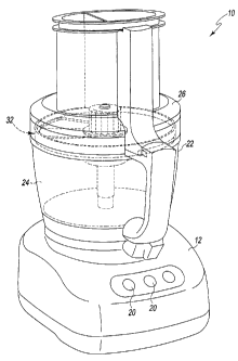
[0022] Referring to FIG. I, a food processing device or food processor 10
is
shown. One example of a food processor is the KitchenAide 12-Cup
Ultra Wide MouthTM Food Processor, Base Model No. KFPW7600B,
which is commercially available from Whirlpool Corporation of
Benton Harbor, MI, U.S.A. The food processor 10 has a base 12 that
houses a motor 14 (shown schematically in FIG. 2) and a control unit
(not shown). Under the control of the control unit, the motor's output
CA 02736231 2016-03-09
shaft 16 drives a cutting blade 18 (see FIG. 2) to cut food items such as
cheeses, meats, fruits, and vegetables. The base 12 also includes one or
more buttons, switches, dials, or other types of controls 20. A user
operates the controls 20 to control the operation of the motor 14 and
hence the food processor 10. For instance, one of the controls 20 may
be operable to turn the motor 14 on and off, while another control 20
may change the motor's speed.
[0023] As will be understood by those skilled in the art, the control unit
may
comprise analog and/or digital circuitry to process electrical signals
received from the motor 14 (or other components of the food processor
10) and provide electrical control signals to the motor or other
components of the food processor 10. For example, the control unit
may be embodied as a microcontroller that executes firmware routines
to control the operation of the food processor 10.
[0024] A removable bowl 22 is secured to the base 12. The bowl's handle
facilitates placement of the bowl 22 on the base 12. The bowl 22
includes a removable lid 26 secured to its upper peripheral edge. The
lid 26 has a feed tube 28 formed thereon through which food items such
as fruits and vegetables are inserted into the bowl 22 to be processed by
the food processor 10. Collectively, the lid 26 and the bowl 22 define a
CA 02736231 2016-03-09
11
processing chamber 24 where food items are processed by the cutting
blade 18.
[0025] The bowl 22, lid 26, and feed tube 28 are generally made of a
transparent or translucent plastic material, so that the contents of the
food processor 10 can be viewed by a user without removing the lid 26
from the bowl 22. Moreover, one or more locking mechanisms may be
used to lock the bowl to the base 12 and the lid 26 to the bowl 22.
[0026] As shown in FIGS. 2 and 3, when the removable bowl 22 is secured to
the base 12, the output shaft 16 of the motor 14 is coupled to a drive
stem 30. The drive stem 30 is in turn coupled to a food slicer assembly
32. As shown in FIGS. 2-4, the food slicer assembly 32 includes a
rotating disk 34, a thickness adjustment assembly 36, and a blade
assembly 38, with the cutting blade 18 being one component thereof.
The rotating disk 34 effectively divides the processing chamber 24 into
an upper compartment 40 located between the disk 34 and the lid 26,
and a lower compartment 42 located below the rotating disk 34. A
vertical distance, D, between the cutting edge 44 of the cutting blade 18
and the upper surface 46 of the rotating disk 34 defines a cutting
thickness. In other words, the thickness of the pieces of food items cut
by the food processor 10 is determined by the distance D between the
cutting edge 44 of the cutting blade 18 and the upper surface 46 of the
CA 02736231 2016-03-09
12
rotating disk 34. When the distance D between the cutting edge 44 of
the cutting blade 18 and the upper surface 46 of the rotating disk 34 is
increased, thicker pieces of food items are created, with thinner pieces
of food items being created when the distance D between the cutting
edge 44 of the cutting blade 18 and the upper surface 46 of the rotating
disk 34 is decreased.
[0027] The rotating disk 34 includes a planar body 52 and a rim 54 that
extends upwardly from the outer perimeter of the planar body 52. The
rotating disk 34 has a diameter that is slightly less than the inner
diameter of the bowl 22 such that the rim 54 is positioned adjacent to,
but spaced slightly apart from, the inner wall of the bowl to permit
rotation of the disk 34 within the bowl 22. In the exemplary
embodiment described herein, the rotating disk 34 is embodied as a
monolithic structure (e.g., a single molded or cast part). However, it
should be appreciated that the components of the rotating disk 34 (e.g.,
body 52 and rim 54) may be embodied as separate components secured
to one another by an adhesive or other suitable fastener.
[0028] The thickness adjustment assembly 36 is operable by a user to vary
the
cutting thickness of the food processor 10 thereby creating thicker or
thinner pieces of cut food items. The adjustment assembly 36 includes
a hub 60 and a user-operated control device 62. The hub 60 includes a
CA 02736231 2016-03-09
_
._
13
base 64 and a hollow sleeve 66 extending upwardly therefrom. A
number of fasteners 68 (i.e., screws) extend through the planar body 52
into the base 64, thereby rigidly securing the rotating disk 34 to the hub
60. It will be appreciated that in other embodiments the hub 60 and the
rotating disk 34 may be integrally formed as a monolithic structure. As
shown in FIGS. 2 and 3, the sleeve 66 extends through an opening 69
formed in the planar body 52. External threads 70 are defined on a
portion of an outer surface 72 of the sleeve 66.
[0029] The user-operated control device 62 is positioned above
the upper
surface 46 of the rotating disk 34. As shown in FIGS. 2-4, the user-
operated control device 62 includes a control knob 74. The control
knob 74 has a body 76 that extends from a lower end 78 to an upper
end 80. The body 76 includes a knurled grip 82 formed in the upper
end 80 and an annular flange 84 extending outwardly from the lower
end 78. It should be appreciated that other user-activated control
devices, such as levers, dials, buttons, or the like, may be substituted
for the control knob.
[0030] As shown in FIGS. 2 and 3, the body 76 of the control
knob 74 has an
aperture 86 formed in the lower end 78 that receives the sleeve 66 of
the hub 60. The inner surface 88 of the aperture 86 has internal threads
90 defined therein that correspond to the external threads 70 of the hub
CA 02736231 2016-03-09
14
60. The internal threads 90 of the control knob 74 threadingly engage
the external threads 70 of the hub 60 to move the hub 60 (and hence the
rotating disk 34) upwardly and downwardly relative to the cutting blade
18. For example, clockwise rotation of the control knob 74 causes
upward movement of the hub 60 (and hence the rotating disk 34), while
counter-clockwise rotation of the control knob 74 causes downward
movement of the hub 60 (and hence the rotating disk 34).
[0031] As shown in FIGS. 2 and 3, a central shaft 98 of the blade
assembly 38
is received in the hollow sleeve 66 of the adjustment assembly 36 and
is secured at an upper end 102 to the control knob 74. The central shaft
98 extends from the upper end 102 to a lower end 104, which is has an
opening 106 that receives the drive stem 30. In that way, the slicer
assembly 32 is coupled to the output shaft 16 such that the slicer
assembly 32 may be driven by the motor 14. The blade assembly 38
also includes a mounting arm 110 extending from an inner end 112,
which is secured to the lower end 104 of the central shaft 98, to an
outer end 114, which is positioned adjacent to the rim 54 of the rotating
disk 34. In the illustrative embodiment, the central shaft 98 and
mounting arm 110 are formed as a single monolithic component from a
plastic or metallic material. It should be appreciated that in other
embodiments the shaft 98 and arm 110 may be formed as separate
CA 02736231 2016-03-09
components that are joined during final assembly by an adhesive or
other suitable fastener.
[0032] The cutting blade 18 is secured to an upper surface 116 of the
mounting
arm 110. A number of fasteners 120 (i.e., screws) positioned at a rear
edge 122 of the cutting blade 18 extend into the mounting arm 110,
thereby rigidly securing the cutting blade 18 to the mounting arm 110.
It will be appreciated that in other embodiments the fasteners 120 may
take the form of T-stakes, pins, posts, or other structures capable of
securing the cutting blade 18 to the mounting arm 110. Additionally,
the mounting arm 110 may include an overmold that receives the
cutting blade 18.
[0033] As shown in FIG. 4, the opening 69 formed in the planar body 52
extends radially outward and receives the mounting arm 110 and the
cutting blade 18. When the food slicer assembly 32 is assembled, a gap
or throat 124 is defined between the cutting edge 44 and the body 52, as
best seen in FIGS. 4 and 5. The food slicer assembly 32 also includes a
counterweight 126 coupled to the planar body 52 adjacent to the outer
perimeter of the rotating disk 34. As shown in FIGS. 2 and 3, the hub
60 is positioned between the counterweight 126 and the cutting blade
18. The counterweight 126 is sized to offset the weight of the
mounting arm 110 and the cutting blade 18. In that way, the
CA 02736231 2016-03-09
16
counterweight 126 balances the slicer assembly 32 as it is rotated. In
other embodiments, the separate counterweight 126 may be omitted
and additional material may be added to the rim 54 and the planar body
52 such that the counterweight is incorporated into the rotating disk 34.
[0034] During operation, the user may change the cutting position of the
rotating disk 34 using the control knob 74. When the control knob 74
is rotated, the hub 60 translates upwardly and downwardly along the
central shaft 98 to change the thickness of the food items being
processed by the food processor 10. In particular, counter-clockwise
rotation of the control knob 74 causes downward movement of the hub
60 (and hence rotating disk 34), which increases the distance D
between the cutting edge 44 of the cutting blade 18 and the upper
surface 46 of the rotating disk 34 and thereby produces thicker pieces
of food items. Oppositely, when the control knob 74 is rotated
clockwise, the hub 60 is moved upwardly along the central shaft 98 and
the distance D between the cutting edge 44 of the cutting blade 18 and
the upper surface 46 of the rotating disk 34 is decreased, thereby
producing thinner pieces of food items.
[0035] When the food processor 10 is activated, the motor 14 causes the
blade
assembly 38 to rotate. The blade assembly 38 acts on the hub 60
secured to the rotating disk 34 such that the rotating disk 34 and the
CA 02736231 2016-03-09
17
blade assembly 38 rotate together. Food items inserted through the
feed tube 28 are urged into contact with the upper surface 46 of the
rotating disk 34 while being acted upon (i.e., cut) by the cutting blade
18. Cut food items, along with other food items small enough to fit
within the throat 124, pass from the upper compartment 40 through the
throat 124.
[0036] A ramp 130 defined in the mounting arm 110 guides food items from
the upper compartment 40 to the lower compartment 42. As shown in
FIG. 5, the ramp 130 is positioned adjacent to and below the cutting
blade 18 and includes an inclined surface 132 extending downwardly
from the underside of cutting blade 18. The inclined surface 132
extends from the inner end 112 of the mounting arm 110 radially
outward to the outer end 114 of the mounting arm 110. As shown in
FIGS. 2 and 3, the inner end 112 defines an inner sidewall 134 for the
ramp 130, while the outer end 114 of the mounting arm 110 defines an
outer sidewall 136. In that way, the inclined surface 132 is
encapsulated or captured between the sidewalls 134, 136, thereby
reducing the potential for food items to travel outside of the processing
path and thus reducing unwanted debris.
[0037] As shown in FIGS. 5 and 6, the slope or angle of the inclined
surface
132 relative to the cutting blade 18 changes as the inclined surface 132
CA 02736231 2016-03-09
18
extends radially outward. As shown in FIG. 5, which is a cross-section
of the slicer assembly 32 taken at the outer end 114 of the mounting
arm 110, the inclined surface 132 has an angle of inclination a at the
outer end 114. As shown in FIG. 6, which is a cross-section of the
slicer assembly 32 taken at the inner end 112 of the mounting arm 110,
the inclined surface 132 has an angle of inclination 13 that is greater than
the angle a. In the illustrative embodiment, the angle a is
approximately 15 degrees, and the angle 13 is approximately 25 degrees.
It will be appreciated that in other embodiments the angles a, 13 may be
greater than or less than those of the illustrative embodiment.
Additionally, in some embodiments, the angles a, 13 may be equal. In
still other embodiments, the inclined surface 132 may be convex or
concave in one or more directions.
[0038] While the disclosure has been illustrated and described in detail
in the
drawings and foregoing description, such an illustration and description
is to be considered as exemplary and not restrictive in character, it
being understood that only illustrative embodiments have been shown
and described and that all changes and modifications that come within
the spirit of the disclosure are desired to be protected.
[0039] For example, while food processing device 10 is herein illustrated
as a
conventional domestic food processor, the features and aspects
CA 02736231 2016-03-09
19
disclosed herein can also be implemented in other types of food
processing devices such as automatic food slicers, dicers, ice shavers
and the like. Similarly, in other embodiments, the rotating disk could
be directly coupled to motor, and the blade could be moveable relative
to the rotating disk.
100401 There are a plurality of advantages of the present disclosure
arising
from the various features of the method, apparatus, and system
described herein. It will be noted that alternative embodiments of the
method, apparatus, and system of the present disclosure may not
include all of the features described yet still benefit from at least some
of the advantages of such features. Those of ordinary skill in the art
may readily devise their own implementations of the method,
apparatus, and system that incorporate one or more of the features of
the present invention and fall within the scope of the present disclosure
as defined by the appended claims.