Note: Descriptions are shown in the official language in which they were submitted.
CA 02736648 2011-04-04
HAMMER TACKER
BACKGROUND OF THE INVENTION
Field of the Invention
The present invention relates to a manual nailing device, and more
particularly to
a hammer tacker.
Description of the Prior Art
A conventional hammer tacker includes a handle and a magazine slidably
received in the handle. An engagement slot is disposed on a distal end of the
handle.
An engagement portion is disposed on a distal end of the magazine. The
engagement
portion is able to engage with the engagement slot so as to keep the magazine
in the
handle.
When filling nails, tacks, or staples, the user has to operate the hammer
tacker
with two hands together. One hand holds the hammer tacker. The other hand
presses
the distal end of the magazine to make the engagement portion disengage from
the
engagement slot. The magazine is then drawn from the handle. The staples can
be
filled into the handle after the magazine is departed from the handle.
However, it is inconvenient to fill the staples into the conventional hammer
tacker. Users must disengage the magazine with both of user's hands. That is,
user
can hardly take other tool or apparatus at the same time. Secondly, the
magazine
should be drawn completely out of the handle before the staples are filled in.
For
filling staples, user has to leave the magazine aside and take the staples.
The
magazine may be forgotten or lost in worksite, or the magazine may fall out
form a
high altitude.
CA 02736648 2011-04-04
The present invention is, therefore, arisen to obviate or at least mitigate
the
above mentioned disadvantages.
SUMMARY OF THE INVENTION
The main object of the present invention is to provide a hammer tacker which
can be filled with staples or nails easily and quickly.
To achieve the above and other objects, a hammer tacker of the present
invention
includes a shell, a magazine, a switch, and a striking mechanism.
The shell defines an inner chamber therein. The shell includes a handle and a
head. The head is located at one end of the handle. The head has a bottom
opening.
The receiving tank is disposed in the inner chamber. The receiving tank
defines a
space. The space has an opening facing downward. The space communicates with
the bottom opening of the head.
The magazine is slidably received in the receiving tank. A receiving slot is
defined between the magazine and the receiving tank. The receiving slot is
adapted
for nailing units to be received therein. The magazine has a bottom surface.
The
bottom surface is formed with a retaining slot.
The switch is disposed on a bottom of the shell. The switch is pivotable about
an
axis. The switch has a press portion and a retaining portion. The press
portion and
the retaining portion are located at two sides of the axis. The press portion
and the
retaining portion achieve an operative relationship. A retaining protrusion
extends
from the retaining portion. The retaining protrusion selectively engages with
the
retaining slot so as to prohibit movement of the magazine.
The striking mechanism is disposed on the head. The striking mechanism is
2
CA 02736648 2011-04-04
adapted for striking the nailing units.
Further, the retaining protrusion disengages from the retaining slot when the
press portion is pressed, so that the magazine resumes to a slidable
condition.
The present invention will become more obvious from the following description
when taken in connection with the accompanying drawings, which show, for
purpose
of illustrations only, the preferred embodiment(s) in accordance with the
present
invention.
BRIEF DESCRIPTION OF THE DRAWINGS
Fig. 1 is a breakdown drawing showing a first embodiment of the present
invention;
Fig. 2 is a combination drawing showing a first embodiment of the present
invention;
Fig. 3 is an AA profile of Fig. 2;
Fig. 4 is a stereogram showing a first embodiment of the present invention
when
the switch is pressed.
DETAILED DESCRIPTION OF THE PREFERRED EMBODIMENTS
Please refer to Fig. I to Fig. 3 for a first embodiment of the present
invention.
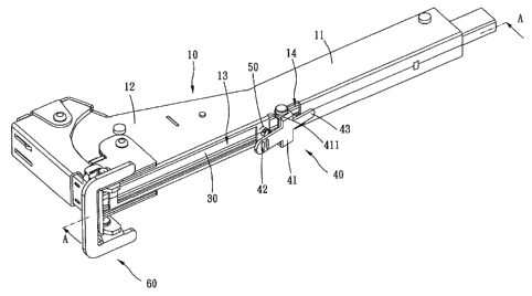
The hammer tacker of the present embodiment includes a shell 10, a receiving
tank
20, a magazine 30, a switch 40, an elastic member 50, and a striking mechanism
60.
The shell 10 defines an inner chamber therein. The shell 10 includes a handle
11
and a head 12 which is located at one end of the handle 11. The handle II is
provided for user to hold. The handle 11 may be covered by elastic or flexible
material for comfort purpose. The handle 11 has an opened distal end. The head
12
3
CA 02736648 2011-04-04
has a bottom opening 13. More particularly, the shell 10 may include a
plurality of
plates. In the present embodiment, the shell 10 is constructed by a left plate
and a
right plate.
The receiving tank 20 is firmly disposed in the inner chamber. The receiving
tank
20 has a top surface 21 and two side surfaces 22 extending downwardly from two
sides of the top surface 21. The receiving tank 20 defines a space which has
an
opening facing downward. The bottom opening 13 of the head 12 communicates
with the space.
The magazine 30 is slidably received in the receiving tank 20. The magazine 30
has a bottom surface 31 and a track 32 formed upon the bottom surface 31. The
magazine 30 and the receiving tank 20 define a receiving slot therebetween.
The
receiving slot is provided for nailing units to be received therein.
Preferably, the
nailing units may straddle across the track 32 or erect by the track 32 so as
to be kept
vertically for striking. The bottom surface 31 is formed with a retaining slot
33.
Preferably, the retaining slot 33 is located at a middle portion of the
magazine 30.
The switch 40 is disposed on a bottom of the shell 10. The switch 10 is
pivotable
about an axis. The switch has a pivoting section 41, a press portion 42, and a
retaining portion 43. The press portion 42 and the retaining portion 43 are
located at
two sides of the axis. In other words, the axis is located between the press
portion 42
and the retaining portion 43. The pivoting section 41 is located between the
press
portion 42 and the retaining portion 43. A pair of pivoting slabs extends from
the
pivoting section 41. The pivoting slabs are rotatably disposed on the bottom
of the
shell 10, so that the switch 40 is able to pivot with respect to the shell 10.
Further,
4
CA 02736648 2011-04-04
...................
the press portion 42 and the retaining portion 43 are made of a single piece
to
achieve an operative relationship. One of the press portion 42 and the
retaining
portion 43 is raised when the other one is pressed. The press portion 42 is
provided
for user to press so as to determine position of the switch 40. A retaining
protrusion
431 extends toward the magazine 30 from the retaining portion 43. The
retaining
protrusion 431 selectively engages with the retaining slot 33 so as to
prohibit
movement of the magazine 30. Preferably, the retaining protrusion 431 has a
first
surface facing the head 12 and a second surface facing the distal end of the
handle 11.
When the retaining protrusion 431 engages with the retaining slot 33, the
first
surface is perpendicular to the magazine 30. The second surface may be made
chamfered or rounded.
The elastic member 50 exerts a resilient force on the switch 40, so that the
retaining portion 43 has a tendency to move toward the magazine 30. More
particularly, the elastic member 50 can be disposed between the switch 40 and
the
shell 10. One end of the elastic member 50 abuts against the press portion 42
to push
the press portion 42 raise. In the present embodiment, the elastic member 50
is a coil
spring. In other possible embodiments of the present invention, the elastic
member
50 may be a torsion spring or other elements which is able to introduce the
resilient
force.
The striking mechanism 60 is disposed on the head 12. The striking mechanism
60 is adapted for striking the nailing units. More particularly, the striking
mechanism
60 may include an operation portion, a striking plate, and a transmission
unit. The
transmission unit is operated between the operation portion and the striking
plate,
5
CA 02736648 2011-04-04
leading that the striking plate has a movement direction opposite to a
movement
direction of the operation portion. When the operation portion strikes a
target, the
transmission unit drives the striking plate to move. The striking plate then
strikes the
nailing unit forward.
Please refer to Fig. 4. When the press portion 42 is pressed, the retaining
protrusion 431 disengages from the retaining slot 33. The magazine 30 then
resumes
to a slidable condition. The magazine 30 can slide outwardly from the distal
end of
the handle 11. User can fill nailing units in the receiving tank 20 via the
bottom
opening 13.
To prevent the magazine 30 from falling out from the receiving tank 20, the
present invention may further include an anti-escape means for prohibiting
departure
of the magazine 30 from the receiving tank 20. For example, the anti-escape
means
may include a protrusion and a groove which are located on proper positions so
as to
selectively engage with each other. In the present embodiment, an abutting
protrusion 35 is disposed on the bottom surface 31 of the magazine 30. The
abutting
protrusion 35 is located about a front end of the bottom surface 31. The shell
10 is
formed with an aperture 14. The retaining protrusion 431 of the retaining
portion 43
can pass through the aperture 14 and abut against the retaining slot 33 or the
abutting
protrusion 35. As such, when the magazine 30 slides outwardly, the abutting
protrusion 35 is able to abut against the retaining protrusion 431. Departure
of the
magazine 30 from the receiving tank 20 is prohibited.
For convenience purpose, the switch 40 may be located between the handle 11
and the head 12. The switch 40 is then located behind the bottom opening 13.
As
6
CA 02736648 2011-04-04
such, the hammer tacker of the present embodiment can be operated by single
hand.
Accordingly, user can operate the hammer tacker with single hand. The magazine
40 slides outwardly after the switch 40 is pressed. User can fill the nailing
units via
the bottom opening 13 with the other hand. The magazine 40 is then pushed to
return
the initial position.
To conclude, user can operate the hammer tacker with single hand, and can fill
the nailing units with the other hand. Nail units filling is easier and
quicker. Further,
the magazine can be kept on the shell and the receiving tank. The magazine
would
not be lost in worksite.
7