Note: Descriptions are shown in the official language in which they were submitted.
CA 02736805 2016-05-17
ABRASIVE PARTICLES HAVING A UNIQUE MORPHOLOGY
TECHNICAL FIELD AND INDUSTRIAL APPLICABILITY
[2]The present invention relates to abrasive particles having a unique
morphology. More
particularly, the invention relates to roughening the surface of diamond
particles to
enhance their performance in industrial applications.
BRIEF DESCRIPTION OF THE DRAWINGS
[WIGS. 1A-1F are scanning electron microscope (SEM) images of conventional
monocrystalline diamond, modified diamond using a nickel coating process and
diamond
modified using an iron powder process.
[41FIG. 2 is a Table 1 showing the physical characteristics and performance of
4-8 pm
diamond particles, e.g. powders, before and after modification.
[S]FIG. 3 is a graph that shows the surface roughness distribution of
conventional diamond
powder, modified diamond powder using a nickel coating process and a diamond
powder
modified using an iron powder process.
[WIG. 4 is a graph that shows the sphericity distribution of conventional
diamond powder,
modified diamond powder using a nickel coating process and a diamond powder
modified
using an iron powder process.
1
CA 02736805 2011-03-10
WO 2010/033575
PCT/US2009/057133
[7]FIG. 5 is a graph showing the material removal rate and resulting surface
finish of
sapphire wafers from a lapping process using slurries made from various
diamond powders
including modified diamond powder using a nickel coating process.
[WIGS. 6A and 6B are comparative drawings of conventional diamond particle
(6A) and a
modified diamond particle (6B).
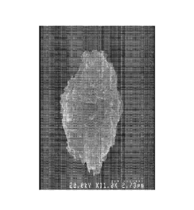
[9]FIG. 7 is an SEM image of a conventional diamond particle.
[1O]FIG. 8 is an SEM image of a modified diamond particle using a nickel
coating process.
[11]FIG. 9A-9D are scanning electron microscope (SEM) images of the diamond
particles of
an embodiment.
[12]FIGS. 10A-10D are scanning electron microscope (SEM) images of the diamond
particles of an embodiment.
[13]FIGS. 11A-11D are scanning electron microscope (SEM) images of the diamond
particles of an embodiment.
[14]FIG. 12 is a scanning electron microscope (SEM) image of conventional
monocrystalline
diamond particles.
[15]FIG. 13 shows Table 1 describing characteristics and performance of the
diamond
particles of an embodiment.
[16]FIG. 14 is a graph depicting characteristics and performance of the
diamond particles of
an embodiment.
[17]FIG. 15 is a graph showing the characteristics of the diamond particles of
an
embodiment.
[18]FIG. 16 is a scanning electron microscope (SEM) image of a diamond
particle of an
embodiment.
[19]FIG. 17 is a scanning electron microscope (SEM) image of a diamond
particle of an
embodiment.
[20]FIG. 18 is a scanning electron microscope (SEM) image of a diamond
particle of an
embodiment.
[21]FIG. 19 is a scanning electron microscope (SEM) image of a diamond
particle of an
embodiment.
[22]FIG. 20 is a scanning electron microscope (SEM) image of a diamond
particle of an
embodiment.
2
CA 02736805 2017-01-17
[23]FIG. 21 is a scanning electron microscope (SEM) image of a diamond
particle of an
embodiment.
[24]FIG. 22 is a graph comparing the lapping performance of conventional
monocrystalline
diamond particles, conventional polycrystalline diamond particles and the
monocrystalline
diamond particles of an embodiment.
[25]FIG. 23 shows Table 2 containing experimental conditions.
[261FIG. 24 is an illustration supplementing the "Definitions" section.
[27]FIG. 25 is an illustration supplementing the "Definitions" section.
[28]FIG. 26 is an illustration supplementing the "Definitions" section.
[29]FIGS. 27A and 27B are SEM images of diamond particles of an embodiment.
[30]DETAILED DESCRIPTION
Before the present methods, systems and materials are described, it is to be
understood that
this disclosure is not limited to the particular methodologies, systems and
materials
described, as these may vary. It is also to be understood that the terminology
used in the
description is for the purpose of describing the particular versions or
embodiments only,
and is not intended to limit the scope. For example, as used herein and in the
appended
claims, the singular forms "a," "an," and "the" include plural references
unless the context
clearly dictates otherwise. In addition, the word "comprising" as used herein
is intended to
mean "including but not limited to." Unless defined otherwise, all technical
and scientific
terms used herein have the same meanings as commonly understood by one of
ordinary
skill in the art.
[31]Unless otherwise indicated, all numbers expressing quantities of
ingredients, properties
such as size, weight, reaction conditions and so forth used in the
specification and claims
are to the understood as being modified in all instances by the term "about".
Accordingly,
unless indicated to the contrary, the numerical parameters set forth in the
following
specification and attached claims are approximations that may vary depending
upon the
desired properties sought to be obtained by the invention.
3
CA 02736805 2017-01-17
[321As used herein, the term "about" means plus or minus 10% of the numerical
value of the
number with which it is being used. Therefore, about 50% means in the range of
45%-
55%.
Definitions
[331In describing and claiming the invention, the following terminology will
be used in
accordance with the definitions set forth below.
[34]The term "abrasive", as used herein, refers to any material used to wear
away softer
material.
[35]The term "material removal", as used herein, refers to the weight of a
workpiece removed
in a given period of time reported in milligrams, grams, etc.
[361The term, "material removal rate", as used herein, refers to material
removed divided by
the time interval reported as milligrams per minute, grams per hour, etc.
[37]The term "monocrystalline diamond", as used herein, refers to diamond that
is formed
either by high-pressure/high-temperature synthesis or a diamond that is
naturally formed.
Fracture of monocrystalline diamond proceeds along atomic cleavage planes. A
monocrystalline diamond particle breaks relatively easily at the cleavage
planes.
[38]The term "particle" or "particles", as used herein, refers to a discrete
body or bodies. A
particle is also considered a crystal or a grain.
4
CA 02736805 2011-03-10
WO 2010/033575
PCT/US2009/057133
[39]The term "pit", as used herein, refers to an indentation or crevice in the
particle, either an
indentation or crevice in the two-dimensional image or an indentation or
crevice in an
object.
[40]The term "polycrystalline diamond", as used herein, refers to diamond
formed by
explosion synthesis resulting in a polycrystalline particle structure. Each
polycrystalline
diamond particle consists of large numbers of microcrystallites less than
about 100
angstroms in size. Polycrystalline diamond particles do not have cleavage
planes.
[41]The term "spike", as used herein, refers to a sharp projection pointing
outward from the
centroid of a particle, a sharp projection pointing outward from the centroid
of a two-
dimensional image or a sharp projection pointing outward from an object.
[42]The term "superabrasive", as used herein, refers to an abrasive possessing
superior
hardness and abrasion resistance. Diamond and cubic boron nitride are examples
of
superabrasives and have Knoop indentation hardness values of over 3500.
[43]The term "weight loss", as used herein, refers to the difference in weight
of a group of
particles before being subject to the modification treatment and the weight of
the same
mass of diamond particles or abrasive particles after being subjected to the
modification
treatment.
[44]The term "workpiece", as used herein, refers to parts or objects from
which material is
removed by grinding, polishing, lapping or other material removal methods.
[45]The term "perimeter", as used herein, refers to the boundary of a closed
plane figure or
the sum of all borders of a two-dimensional image.
[46]The term "convex perimeter", as used herein, refers to a line joining
Feret tangent points,
where Feret is the distance between two parallel tangents touching the
boundary on each
side of a two dimensional image or object. FIGS. 24-26 provide illustrations
of these
concepts.
CA 02736805 2016-05-17
[47]The term "surface roughness", as used herein, refers to the measurement of
a two-
dimensional image that quantifies the extent or degree of pits and spikes of
an object's
Tk4
edges or boundaries as stated in the CLEMEX image analyzer, Clemex Vision
User's
Guide PE 3.5 2001. Surface roughness is determined by the ratio of the convex
perimeter divided by the perimeter.
ConvexPerimeter
i. Surface Roughness = ________________________
Perimeter
[48]Note that as the degree of pits and spikes increases, the surface
roughness factor
decreases.
[49]The term "sphericity", as used herein, refers to the estimate of the
enclosed area of a two
dimensional image or object (47tA) divided by the square of perimeter (p2).
4,4
i. Sphericity =
[50]The term "surface area" as used herein, refers to the external surface of
a particle. When
used with a plurality of particles, i.e., powder, the term specific surface
area is used and is
reported as surface area per gram of powder.
[51]The term "wafer roughness" when referring to the surface of the sapphire
are the features
on the surface of the wafer. These features, which include the fine scratches
or track marks
from abrasive polishing, are measured using a contact or non-contact
profilometer.
[52]The terms diamond particle or particles and diamond powder or powders are
used
synonymously in the instant application and have the same meaning as
"particle" defined
above.
[53]It is important to note that although the terms defined above refer to
measuring two-
dimensional particle profiles using microscopic measuring techniques, it is
understood that
the features extend to the three-dimensional form. Automated image analysis of
particle
size and shape is recognized by one skilled in the art as a reliable,
reproducible method of
6
CA 02736805 2011-03-10
WO 2010/033575
PCT/US2009/057133
measuring particle characteristics. Although the CLEMEX image analyzer was
used,
similar devices are available that will reproduce the data.
[54]In one embodiment, monocrystalline diamond particles may be used.
Monocrystalline
diamond particles in sizes of less than about 100 microns are useful. However,
diamond
particles in sizes over about 100 microns may be used as well. The sizes of
the diamond
particles range from about 0.1 to about 1000 microns. One example of diamond
particles
that may be used is SJK-5 4-8 micron, synthetic industrial diamond particles
manufactured
by Diamond Innovations, Inc. (Worthington, Ohio, U.S.A).
[55]In another embodiment, natural diamond particles, sintered polycrystalline
diamond or
shock synthesized polycrystalline diamond particles may be subjected to the
modification
treatment discussed below.
[56]In an embodiment, other abrasives may be subjected to a modification
treatment.
Examples of abrasives include any material, such as minerals, that are used
for shaping or
finishing a workpiece. Superabrasive materials such as natural and synthetic
diamond and
boron, carbon and nitrogen compounds may be used. Suitable diamond materials
may be
crystalline or polycrystalline. Other examples of abrasive grains may include
calcium
carbonate, emery, novaculite, pumice dust, rouge, sand, ceramics, alumina,
glass, silica,
silicon carbide, and zirconia alumina.
[57]In another embodiment, a reactive coating is used to modify the abrasive
or superabrasive
particles. Such reactive coatings include but are not limited to alkali metal
hydroxides,
such as lithium hydroxide, sodium hydroxide, potassium hydroxide, potassium
carbonate,
sodium peroxide, potassium dichromate and potassium nitrate, etc. The reactive
coatings
may also include a combination of alkali metal hydroxides.
[58]Still other examples of metals that may be utilized as the reactive
coating are those
included in Group VIII of the Periodic table, their metal compounds and
combinations
7
CA 02736805 2011-03-10
WO 2010/033575
PCT/US2009/057133
thereof. Other examples of material that may be used as reactive coatings
include the
catalyst metals taught in U.S. 2,947,609 and the catalyst metals taught in
U.S. 2,947,610.
[59]In an embodiment, a metal coating is used as the reactive coating and the
abrasive
material is diamond. The weight ratio of diamond particles to the metal
coating is about 10
wt % to about 90 wt % Ni or about 10 wt % to about 60 wt % Ni. However, it
should be
noted that these ratios are a matter of economic efficiency rather than
technical
effectiveness. In one embodiment, the metal coating at least partially covers
the diamond
particles. Alternatively, the metal coating may uniformly surround each
diamond particle.
It is not necessary that the metal be chemically bonded to the diamond. Nickel
and/or
nickel alloys may be used as a coating for the diamond. A method of
application of the
nickel to the diamond is with an electroless deposition process however
methods such as
electrolytic plating, physical vapor deposition or chemical vapor deposition
may be used to
coat the diamond particles with a layer of nickel.
[60]In an embodiment, diamond particles are coated with from about 10 to about
60 weight
percent nickel phosphorous coating. The coating process initially subjects the
uncoated
diamond particles to a solution of colloidal palladium. The fine palladium
particles
uniformly adsorb onto the surface of the diamond making the surface
autocatalytic for
electroless deposition of nickel. In the next stage of the process, the
activated diamond is
placed into nickel sulfamate solution containing about 10 grams per liter
dissolved nickel.
While the activated diamond and nickel suspension is mixing, sodium
hypophosphate is
added to the suspension and the temperature of the coating bath is maintained
at about 80
degrees C. When the hypophosphate solution is added, all of the dissolved
nickel in
solution will autocatalytically deposit onto the activated diamond surfaces.
[61]Depending on how much nickel deposits onto the diamond, more nickel may be
added by
replacing the spent nickel/hypophosphate solution with fresh solutions and
repeating the
process. If uniformly coating the particle, several cycles may be required to
obtain a
sufficiently uniform coverage of nickel over each of the diamond particles. By
monitoring
the number of cycles and controlling the coating bath parameters like
temperature, pH and
8
CA 02736805 2011-03-10
WO 2010/033575
PCT/US2009/057133
mixing energy, the nickel content on the diamond is very reproducible. It is
not
uncommon for the coated diamond to have some level of agglomerations as a
consequence
of the interactions of the diamond particles and nickel plating during the
coating. So long
as the individual particles that comprise the agglomerates contain some amount
of nickel
coating, the presence of agglomerates does not affect the quality of the
process and no
attempt at removing agglomerates is required.
[62]After the diamond particles have been coated, the coated particles are
placed into a
furnace and, in a hydrogen atmosphere, vacuum atmosphere, or an inert gas
atmosphere,
heated from about 650 C to about 1000 C. Temperatures of about 700 C to about
950 C
or about 800 C to about 900 C may be used. The coated diamond may be heated
for a
period of time of from about five minutes up to about five hours. Time periods
ranging
from about thirty minutes up to about two hours or of about one to about two
hours may be
used.
[63]After the heating cycle is complete and the particles are cooled, the
modified diamond
particles are recovered by dissolving the nickel coated diamond in common
acids. Acids
that may be used include hydrochloric acid, hydrofluoric acids, nitric acid
and certain
combinations thereof. Acids, or combinations thereof, are added in an acid-to-
coated-
diamond ratio of 100:1 up to 1000:1 (by volume). The mixture is then heated
between
about 100 C to about 120C for a period of from about six to about eight
hours. The
solution is then cooled, the liberated diamond settles and the solution is
decanted. The acid
cleaning and heating steps are repeated until substantially all of the metal
coating has been
digested.
[64]Subsequently, any converted graphite (carbon from diamond that has been
converted to
graphite during the reaction with nickel) is then removed from the diamond
particles via
any dissolution treatment method known in the art. An example of a common
dissolution
procedure includes the oxidation of graphitic carbons by gradual heating range
between
about 150 C to about 180 C in an acidic solution containing a mixture of HNO3
and
H2504
9
CA 02736805 2011-03-10
WO 2010/033575
PCT/US2009/057133
[65]Depending on the furnace conditions chosen, more or less reaction may
occur between
the metal and the diamond. The more the metal etches into the diamond, the
more graphite
is formed and, thus, more weight is lost by the diamond. To completely
dissolve the
graphite, higher quantities of acid may be used or additional dissolution
treatments may be
necessary. The diamond particles are then washed to remove acids and residue,
such as in
water. Subsequently, the diamond particles are dried in an oven, air dried,
subjected to
microwave drying or other drying methods known in the art.
[66]One embodiment pertains to monocrystalline diamond particles having very
rough,
irregular surfaces as shown in FIGS. 1C and 1D. FIG. 1D shows a population of
diamond
particles and FIG. 1C shows an enlargement of a particle from FIG. 1D. The
particles
have been modified using the method described above. In addition to the
roughened
appearance, the modified diamond particles have unique characteristics as
compared to
conventional monocrystalline diamond particles shown in FIGS. 1A and 1B. FIG.
1B
shows a population of monocrystalline diamond particles and FIG. 1A shows an
enlargement of a particle from FIG. 1B. The conventional monocrystalline
diamond
particles produced by milling were not subjected to the modification
treatment.
[67]As shown in FIG. 1D, the modified diamond particles include significantly
more spikes
and pits than conventional monocrystalline diamond shown in FIG. 1A. The
spikes act as
cutting edges when used in free-abrasive slurry applications. It has been
discovered that
the performance of the diamond particles of the instant application
significantly improves
when used in free abrasive lapping applications within a liquid slurry or
suspension. When
the modified diamond particles are used in a fixed bond system, the pits and
the spikes
help secure the particle within the bond system.
[68]In an embodiment, metal particles are used to modify the diamond
particles. The weight
ratio of diamond particles to metal particles is 1:5 to 5:1. However, it
should be noted that
these ratios are a matter of economic efficiency rather than technical
effectiveness. The
size of the metal particles is in the range of about 0.05 microns to about 100
microns. The
CA 02736805 2011-03-10
WO 2010/033575
PCT/US2009/057133
size of the metal particles is typically less than the size of the diamond
particles. In an
embodiment, iron particles may be used. Examples of iron particles that may be
used in
the process of an embodiment include grade HQ 1 pm carbonyl iron powder (BASF,
Ludwigshafen, Germany).
[69]Although iron powder has been mentioned as a powder used in carrying out
the process,
other metals such as cobalt, nickel, manganese and chrome and their metal
compounds and
combinations thereof may be used.
[70]In another embodiment of making modified diamond particles, from about 10
to about
80 weight percent diamond particles and from about 20 to about 90 percent iron
particles
are mixed using any appropriate mixing method that achieves a uniform mixture.
In an
embodiment, the weighed portions of the iron and diamond particles are put
into a jar,
sealed and inserted into a mixing device such as a Turbula shaker-mixer (Glen
Mills,
Inc., Clifton, New Jersey, U.S.A) for at least about one hour or,
alternatively, about 30
minutes to about one hour. A binder may optionally be added to the mixture
prior to
mixing. Binders provide lubricity to particle surfaces allowing a denser
packing and more
intimate contact between the metal powder and diamond. Binders also help in
holding a
pressed body together as a green-body.
[71]The mixture is then compressed so as to create an intimate mixture of
diamond particles
and iron particles. Any method may be used to compress the diamond particles
and iron
particles so long that they form an intimate mixture and the particles are in
very close
contact with one another. One method used to compress the mixture is to place
the
mixture into a fixed die set on a press. An example of a suitable press is a
Carver pellet
press manufactured by Carver, Inc. (Wabash, IN). In the die press, the mixture
is subjected
to pressure between about 5 and about 50,000 psi, between about 10,000 to
about 40,000
psi or between about 15,000 to about 30,000 psi to form a pellet. Although
pelletizing the
mixture is taught, it is not necessary that the mixture of diamond and iron
particles be
formed into a pellet, only that the particles be compressed so as to form
intimate contact
11
CA 02736805 2011-03-10
WO 2010/033575
PCT/US2009/057133
with one another. Isostatic or monostatic pressing with deformable tooling may
also be
used to achieve the intimate contact.
[72]Alternatively, the mixture may also be compressed by pressing it into a
thin sheet that is
several millimeters to several inches thick, i.e., by high pressure compaction
rolls or
briquetting rolls. The formed sheets may then be cut into smaller sections for
further
processing as discussed below. Another method of compressing the mixture of
iron and
diamond particles includes mixing and extruding the mixture under pressure.
Pelletizing
the mixture of diamond and iron particles via a pelletizer or tumbling the
mixture in a
tumbling apparatus are also alternative methods that may be used to compress
the mixture.
The pellets, bricks, briquetttes or cakes be formed by these methods may then
be further
processed as discussed below
[73]Additional methods of compressing the mixture of iron and diamond
particles include
injection molding, extrusion, pressing the mixture into a container or tape
casting.
Alternatively, individual diamond particles may be coated with metal particles
by ion
implantation, sputtering, spray drying, electrolytic coating, electroless
coating or any other
applicable method so long as, the iron and diamond particles are in intimate
contact with
each other.
[74]After compressing the mixture of diamond and iron particles, the
compressed mixture,
which may be in a pellet, an aggregate or other condensed form, is placed into
a furnace
and, in a hydrogen atmosphere, vacuum atmosphere, or an inert gas atmosphere,
heated
from about 650 C to about 1000 C. Temperatures of about 700 C to about 900 C
or about
750 C to about 850 C may be used. The compressed mixture may be heated for a
period
of time of from about five minutes up to about five hours. Time periods
ranging from
about thirty minutes up to about two hours or of about one to about two hours
may be used.
[75]After the heating cycle is complete and the compressed mixture is cooled,
the modified
diamond particles are recovered by dissolving the iron particles in common
acids. Acids
that may be used include hydrochloric acid, hydrofluoric acids, nitric acid
and
12
CA 02736805 2011-03-10
WO 2010/033575
PCT/US2009/057133
combinations thereof. Acids, or combinations thereof, are added in an
acid:compressed
mixture (i.e., a pellet) ratio of 100:1 up to 1000:1 (by volume). The mixture
is then heated
between about 100 C to about 150C for a period of from about six to about
eight hours.
The solution is then cooled, the liberated diamond settles and the solution is
decanted. The
acid cleaning and heating steps are repeated until substantially all of the
iron has been
digested.
[76]Subsequently, any converted graphite (carbon from diamond that has been
converted to
graphite during the reaction with iron) is then removed from the particles via
any
dissolution treatment method known in the art. Example of a common dissolution
procedure includes the oxidation of graphitic carbons by gradual heating range
between
about 150 C to about 180 C in an acidic solution containing a mixture of HNO3
and
H2S 04
[77]Depending on the furnace conditions chosen, more or less reaction may
occur between
the metal and the diamond. The more the metal powder etches into the diamond,
the more
graphite is formed and, thus, more weight is lost by the diamond. To
completely dissolve
the graphite, higher quantities of acid may be used or additional dissolution
treatments may
be necessary. The diamond particles are then washed to remove acids and
residue, such as
in water. Subsequently, the diamond particles are dried in a furnace, air
dried, subjected to
microwave drying or other drying methods known in the art.
[78]An embodiment pertains to monocrystalline diamond particles having very
rough,
irregular surfaces as shown in Fig s.9A-9D; FIGS. 10A-10D and FIGS. 11A-11D.
In
addition to the roughened appearance, the diamond particles have unique
characteristics as
compared to conventional monocrystalline diamond particles shown in FIG. 12.
The
conventional monocrystalline diamond particles produced by milling, shown in
FIG. 12,
were not subjected to the modification treatment.
[79]Referring to FIG. 13, Table 2 contains data including sizes, weight loss,
surface area,
material removal, roughness and sphericity for a sample of monocrystalline
diamond
13
CA 02736805 2011-03-10
WO 2010/033575
PCT/US2009/057133
particles (9 pm). Additionally, comparative data for both a conventional
monocrystalline
diamond particle and a conventional polycrystalline diamond particle of
similar particle
sizes are shown. This data was used to create the graphs in FIGS. 14 and 15 as
discussed
below.
[80]As shown in FIGS. 9A-9D; FIGS. 10A-10D and FIGS. 11A-11D, the diamond
particles
are very different in appearance compared to conventional monocrystalline
diamond
particles as shown in FIG. 12. FIGS. 9A-9D show SEM images of the diamond
particles
of Run #4; FIGS. 10A-10D shows SEM images of the diamond particles of Run#5
and
FIGS. 11A-11D show SEM images of the diamond particles of Run #9. FIG. 13
(Table 2)
lists the corresponding properties and characteristics of the diamond
particles from
additional samples.
[81]As shown in FIGS. 9A-9D; FIGS. 10A-10D and FIGS. 11A-11D, the diamond
particles
include spikes and pits. The spikes act as cutting edges when used in free-
abrasive slurry
applications. It has been discovered that the performance of the modified
diamond
particles significantly improves when used in free abrasive lapping
applications within a
liquid slurry or suspension. When the modified diamond particles are used in a
fixed bond
system, the pits and/or the spikes help secure the particle within the bond
system.
[82]The modified diamond particles exhibit unique characteristics in surface
roughness,
sphericity and material removal. FIG. 14 shows these characteristics as
compared to
weight loss of the modified diamond particles. Details has to how the
measurements were
obtained are discussed in Example IV. As shown in FIG. 14, the weight loss of
the
diamond particles is between greater than 0% to about 70%.
[83]As shown in FIG. 14, diamond particles exhibit a surface roughness of less
than about
0.95. Surface roughness of between about 0.50 and about 0.80 and between about
0.50
and about 0.70 is also observed. Surface roughness of the diamond particle is
a function of
the size of the metal particle(s), amount of metal particle(s) in contact with
the diamond,
reaction time and temperature used. As can be seen in FIG. 14, as the surface
roughness
14
CA 02736805 2011-03-10
WO 2010/033575
PCT/US2009/057133
factor decreases (roughness increases) the ability of the diamond to perform
material
removal in a lapping process (described in EXAMPLE IV) increases from about
125 mg
for a surface roughness factor of about 0.92 to about 200 mg for a surface
roughness factor
of about 0.62; an increase of about 60 percent. This may be attributed to the
increased
number of cutting points that the surface modification provides.
[84]FIG. 14 also shows that the diamond particles also exhibit sphericity
readings of less than
about 0.70. Sphericity readings of about 0.2 to about 0.5 and about 0.25 to
0.4 are also
observed. Although sphericity is an independent feature from surface
roughness, it can be
observed that there is a strong correlation between sphericity and the lapping
performance
of the diamond as shown in FIG. 14. In FIG 14, it can be shown that the
material removal
increases from about 125 mg for a sphericity of about 0.70 to about 200mg for
a sphericity
of about 0.25. Also, as can be seen in FIG. 14, there is a strong correlation
between the
weight loss of the diamond powder and the lapping performance as indicated by
the
increase in material (sapphire) removal. As the weight loss of diamond
increases, the
diamond becomes more aggressive in its ability to remove material.
[85]FIG. 15, is a graph showing diamond weight loss (%) vs. surface area. The
readings were
taken from a population of 9 pm diamond particles. The specific surface area
of the
modified diamond particles having weight loss greater than 35% is about 20%
higher
compared to conventional diamond particles having the same particle size
distribution. It
can be observed that the specific surface area of the particles is directly
proportional to the
extent of the reaction of the diamond particles and iron particles during the
modification
treatment process. For example, specific surface area readings of the diamond
particles
range from about 0.45 to about 0.90 m2/g.
[86]FIGS. 16-19 show examples of various diamond particles that have been
subjected to
varying degrees of treatment with iron. FIG. 16 shows a diamond particle that
was heated
at a temperature of 750 C for 1 hour in 60% by weight iron resulting in a 15%
weight loss
of the diamond particle. Fig. 17 shows a diamond particle that was heated at a
temperature
of 750 C for 1 hour in 80% by weight iron resulting in a 25% weight loss of
the diamond
CA 02736805 2011-03-10
WO 2010/033575
PCT/US2009/057133
particle. Fig. 18 shows a diamond particle that was heated at a temperature of
850 C for 1
hour in 60% by weight iron resulting in a 30% weight loss of the diamond
particle. Fig. 19
shows a diamond particle that was heated at a temperature of 850 C for 1 hour
in 80% by
weight iron resulting in a 45% weight loss of the diamond particle. Figure 20
shows a
diamond particle that was heated at a temperature of 850 C for 2 hours in 60%
by weight
iron resulting in a 53% weight loss of the diamond particle. Fig. 21 shows a
diamond
particle that was heated at a temperature of 850 C for 2 hours in 80% by
weight iron
resulting in a 61% weight loss of the diamond particle.
[87]The modified diamond particles contain one or more pits and/or spikes. An
example of a
diamond particle exhibiting these features is shown in FIG. 19. Diamond
particle 1,
having a weight loss of about 45%, includes pits 4,6 that form spike 2. The
lengths of the
spikes and depths of the pits vary according to the modification treatment
parameters. The
average depth of the pits on a particle ranges in size from about 5% to about
70% of the
longest length of the particle.
[88]The modified abrasive particles, as described above, may be useful in many
applications
including free abrasive applications, fixed abrasive applications, lapping,
grinding, cutting,
polishing, drilling, dicing, sintered abrasives or abrasive compacts, and wire
for wire saws.
In general, one would expect that the roughened surface would aid in the
retention of the
diamond particle within the tool or resin bond system.
[89]With regard to wire saw applications, the abrasive particle may be
attached to a wire by
electroplating, metal sintering or polymeric or resin bonds. Electroplated
wire saws
generally contain a single layer of abrasive particles co-deposited with a
layer of nickel
metal. Some wires also use a resin to attach the abrasives to the wire. The
use of the
modified diamond particles would aid in providing better retention of the
abrasive particle
in the metal or resin matrix, hence increasing the life of the wire saw. The
modified
abrasive particles may also provide higher material removal rate with better
free-cutting
ability.
16
CA 02736805 2011-03-10
WO 2010/033575
PCT/US2009/057133
[90]Materials typically cut with wire saws include silicon, sapphire, SiC,
metals, ceramics,
carbon, quartz, stone, glass composites, and granite.
[91]The abrasive particles are also useful in slurries and other carrier
liquids. A typical slurry
solution may include the modified diamond particles ranging in size of from
about 0.1 to
about 100 microns present in a concentration of about 0.2 to about 50 percent
by weight, a
major vehicle such as a water-based vehicle, glycol-based vehicle, oil-based
vehicle or
hydrocarbon-based vehicles and combinations thereof and optional additives
including
surfactants, pH and color adjusters, and viscosity modifying agents.
[92]In another embodiments, the modified abrasive particles and superabrasives
may be
optionally coated with a coating, after modification, such as a material
selected from
Groups IVA, VA, VIA, Mb and IVb of the periodic table and including alloys and
combinations thereof. A non-metallic coating that may be used is silicon
carbide.
EXAMPLE I
[93]A 4-8 pm monocrystalline diamond particles, e.g., diamond powder, with a
nominal
mean size of 6 pm was coated with a nickel/phosphorous coating (90% Ni/10% P).
The
nickel coated diamond powder contained 30 weight percent NiP and 70 weight
percent
diamond. Each diamond particle was uniformly covered with the NiP coating. Two
25
gram samples of the Ni coated powder were heated in a furnace. One 25 gram
sample was
heated at 825 C for 1 hour and the other at 900 C in a hydrogen atmosphere for
2 hours.
After the heating cycle was completed and the coated diamond powder was cooled
to room
temperature, the modified diamond particles were recovered by dissolving the
nickel
coated diamond in two liters of nitric acid. The mixture was then heated to
120C for a
period of five hours. The solution was then cooled to room temperature, the
liberated
diamond settled and the solution was decanted. The acid cleaning and heating
steps were
repeated one additional time until substantially all of the nickel had been
digested.
17
CA 02736805 2011-03-10
WO 2010/033575
PCT/US2009/057133
[94]After the nickel was removed from the diamond, the converted graphite
(carbon from
diamond that has been converted to graphite during the reaction with nickel)
was then
removed from the particles using 2 liters of sulfuric acid heated to 150 C for
seven hours.
The solution was then cooled to room temperature, the diamond allowed to
settle and the
solution was decanted. The sulfuric acid cleaning and heating steps were
repeated one
additional time until substantially all of the graphite had been digested.
[95]Measurements of weight loss, surface roughness and sphericity were
obtained from the
material recovered from this experiment. Included in this analysis was the SJK-
5 4-81.tm
diamond that was modified using a fine iron powder process as described
herein. Also
included is data for a polycrystalline diamond powder of similar nominal size.
[96]The surface roughness and sphericity were obtained from images of the base
material and
modified diamond particles taken with a Hitachi model S-2600N Scanning
Electron
Microscope (SEM) at a 2500X magnification. The SEM images were saved as TIFF
image
files which were then uploaded into a Clemex image analyzer Vision PE 3.5 that
was
calibrated to the same magnification (2500X). In this example and for this
magnification,
the calibration resulted in 0.0446pm/pixel resolution. The image analysis
system
measured particle size and shape parameters on a particle by particle basis.
Measurements
for a population of at least 50 particles from each set of experiments were
generated
automatically by the Clemex image analyzer. Mathematical formulas used by the
image
analyzer device to derive the measurements are found in the "Definitions"
section above
and can also be found in the Clemex Vision User's Guide PE 3.5 2001. Surface
characteristics of the diamond particles of the five powder samples are shown
in FIG. 2
(Table 1).
[97]As can be seen from FIG. 1C, the surface texture of the modified diamond
particles
produced using the nickel coating method is significantly different than the
surface texture
of the starting material shown in FIG 1A. It is apparent that, at temperatures
above 800 C,
the nickel reacts with the diamond and creates a unique texture that can be
described by
roughness and sphericity factors using the image analysis method. Based on the
data
18
CA 02736805 2011-03-10
WO 2010/033575
PCT/US2009/057133
obtained in this example, the roughness values changed from 0.89 to 0.77 for
the 35
percent weight loss sample and from 0.89 to 0.78 for the 56 percent weight
loss diamond.
The sphericity values changed from 0.64 to 0.47 for the 35 percent weight loss
sample and
from 0.64 to 0.46 for the 56 percent weight loss diamond after the
modification process.
[98]Note that, as can be seen in FIG. 2 (Table 1), although the modification
process at 900 C
results in a higher weight loss of diamond, and a slightly finer size and
slightly higher
specific surface area compared to the process performed at 825 C, there is
essentially no
difference in the roughness and sphericity of these two samples. The surface
texture
produced of the diamond particles can be qualitatively described as having
many small
"teeth" or cutting points. Although these features are most apparent when
looking at the
boundary of particle profiles, they also exist across the entire surface of
each particle. It is
thought that the increase in the number of cutting points, or teeth, is
responsible for the
improved performance of the modified diamond particles. FIG. 6B shows a two-
dimensional illustration of the cutting points or teeth of a modified diamond
particle. FIG.
6A shows a two-dimensional illustration of a conventional monocrystalline
diamond
particle that has not been modified with a metal coating. FIG. 7 is an SEM
image of a
conventional monocrystalline diamond particle that has not been modified with
metal
coating. FIG. 8 is an SEM image of showing the cutting points or teeth of a
diamond
particle modified with a nickel coating.
[99]For purposes of distinction, the surface texture of the modified particles
is different from
the texture that was produced using the iron powder modification process as
taught above.
As shown in FIG. 1E, the iron powder modified particles display deep pits and
spikes. The
average roughness of the iron powder modified diamond is 0.68 and the average
sphericity
is 0.34. As shown in FIGS 3 and 4, these values are significantly different
than the values
measured for the nickel-coated modified diamond particles. It can also be seen
that,
although the particles modified by iron powder do not have as many cutting
points per unit
length of perimeter as the nickel coated modified diamond, the deeper pits and
pockets
could be useful in providing better retention within a bond system.
19
CA 02736805 2011-03-10
WO 2010/033575
PCT/US2009/057133
EXAMPLE II
[100]A MBG-620 70/80 mesh monocrystalline diamond particles was coated with a
nickel/phosphorous coating (90% Ni/10% P). The nickel coated diamond powder
contained 56 weight percent NiP and 44 weight percent diamond. Each diamond
particle
was uniformly covered with the NiP coating. 5 grams sample of the Ni coated
powder
were heated in a furnace at 1000 C for 1 and half hour under hydrogen
environment. After
the heating cycle was completed and the coated diamond powder was cooled to
room
temperature, the modified diamond particles were recovered by dissolving the
nickel
coated diamond in 500m1 of nitric acid. The mixture was then heated to 120C
for a
period of five hours. The solution was then cooled to room temperature, the
liberated
diamond settled and the solution was decanted. The acid cleaning and heating
steps were
repeated one additional time until substantially all of the nickel had been
digested.
[1O1]After the nickel was removed from the diamond, the converted graphite was
then
removed from the particles using 500m1 of sulfuric acid and 100m1 nitric acid
and heated
to 150 C for seven hours. The solution was then cooled to room temperature,
the diamond
allowed to settle and the solution was decanted. The sulfuric acid cleaning
and heating
steps were repeated one additional time until substantially all of the
graphite had been
digested.
[102]A 14% diamond weight loss has been achieved with this experiment. Samples
of the
particles are shown in FIGS. 27A and 27B.
EXAMPLE III
[103]The diamond powders of Example 1 were additionally evaluated in a
sapphire lapping
application. Ethylene glycol-based slurries were made using the
monocrystalline modified
diamond particles ("Nickel Coating Modified Diamond") and, from the same lot,
conventional monocrystalline diamond particles "(Unmodified Diamond") from
which the
nickel coating modified diamond was made. Slurries were also made from iron
powder
modified diamond as described in Example 1 as well as from conventional
polycrystalline
CA 02736805 2011-03-10
WO 2010/033575
PCT/US2009/057133
diamond. The slurries were used for flat-lapping sapphire wafers. The lapping
plate was a
composite copper/resin material (Lapmaster Inc.) and the sapphire wafers were
c-plane, 2
inches diameter, as-lapped surface texture and 4901.tm thick. The lapping
process was
performed using each of the slurries under the same processing conditions and
for the same
amount of time. The diamond concentration in each of the slurries was 10
carats per
500m1 and the viscosity was 15-20 cps. Before each test, the lapping plate was
dressed for
minutes using a 600 grit diamond dressing wheel. The pressure on each of the
sapphire
wafers was 3.2 psi, rotational speed of the lapping plate was 60 rpm and the
slurry feed
rate was 2-3m1 per minute. After each cycle, the wafers were measured for
weight loss.
[104]FIG. 5 is a graph comparing the lapping performance of conventional 4-8
micron
monocrystalline diamond particles in a slurry with 10 carats of diamond in 500
ml slurry,
conventional 4-8 micron polycrystalline diamond particles in a slurry with 10
carats of
diamond in 500 ml slurry and two slurries using modified 4-8 micron
monocrystalline
diamond particles of 35 percent weight loss and 56 percent weight loss using
10 carats of
diamond per 500 ml of slurry. As can be seen from FIG. 5 and in FIG. 2 (Table
1), the
material removal rate of the conventional 4-8 i.tm diamond slurry is 126 mg
per hour per
sapphire wafer. Using the slurry made with the polycrystalline diamond
particles, the
material removal rate was 168 mg/hr. The slurries made using the modified
diamond
particles resulted in material removal rates of 279 mg/hr for the 35 percent
weight loss
powder and 304 mg/hr using the 56 percent weight loss powder.
[105]It can also be seen from the results shown in FIG 5 that, although the
modified diamond
particles provide significantly higher material removal rates, the resulting
roughness (Ra)
of the surface of the sapphire wafers are lower than with the conventional
monocrystalline
diamond and with the polycrystalline diamond. The wafer roughness of wafers
polished
with the polycrystalline diamond slurry was 45.9nm +/- 3.5nm and the wafer
roughness of
wafers polished with the monocrystalline diamond was 51.3nm +/- 2.7nm. By
comparison, the wafer roughness of the sapphire wafers polished using the 35
percent
weight loss diamond was 32.8nm +/- 1.8nm and wafers polished with the 56
percent
21
CA 02736805 2011-03-10
WO 2010/033575
PCT/US2009/057133
weight loss diamond slurry had a wafer roughness of 33.7nm +/- 2.7nm as
measured by a
Veeco Wyco Model NT1100 Optical Surface Profilometer.
[106]As shown in FIG. 2 (Table 1) it can be seen that the specific surface
areas of the
monocrystalline modified diamond particles are 1.29 m2/gram and 1.55 m2/gram
for a 35
percent and 56 percent weight loss diamond respectively. This compares to a
specific
surface area of 0.88 m2/gram or a 47% and 76% increase. This is significant
because the
particle size distributions of the two samples are the same. The increased
surface area is
due to the creation of additional area on the surface of the modified
monocrystalline
diamond particles.
EXAMPLE IV
[107]A 6-12 pm monocrystalline diamond powder with a mean size of 9 pm was
blended with
an iron powder with a mean size of 3 pm using a blend ratio of 30 weight
percent diamond
particles and 70 weight percent iron powder (no binder). The blend was
compacted into a
2 cm x 0.5 cm pellet using a Carver press at a pressure of 20,000 psi. The
pellet was
heated at 700 C for 2 hours in a hydrogen atmosphere. The diamond particles
were
recovered using an acid digestion process. Characteristics of the diamond
particles of this
sample are shown in FIG. 13 (Table 2).
[108]Ethylene glycol-based slurries were made using the monocrystalline
diamond particles of
the present invention ("Modified Diamond") and, from the same lot,
conventional
monocrystalline diamond particles "(Unmodified Diamond") from which the
modified
diamond was made. The slurries were used for flat-lapping sapphire wafers. The
lapping
plate was a composite copper plate and the sapphire wafers were 2 inches in
diameter. The
lapping process was performed using each slurry under the same processing
conditions and
for the same amount of time. The slurry diamond concentration was 10 carats
per 500m1
and the viscosity was 15-20 cps. Before each test, the lapping plate was
dressed for 5
minutes using a 600 grit diamond dressing wheel. The pressure on each of the
sapphire
wafers was 3.2 psi, rotational speed of the lapping plate was 60 rpm and the
slurry feed
rate was 2-3m1 per minute. After each cycle, the wafers were measured for
weight loss.
22
CA 02736805 2011-03-10
WO 2010/033575
PCT/US2009/057133
[109]FIG. 22 is a graph comparing the lapping performance of conventional 6-12
micron
monocrystalline diamond particles in a slurry with 10 carats of diamond in 500
ml slurry,
conventional 8-12 micron polycrystalline diamond particles in a slurry with 10
carats of
diamond in 500 ml slurry and 6-12 micron monocrystalline diamond particles
(Modified 6-
12) in slurries using 10 carats of diamond of the present invention per 500 ml
of slurry and
a slurry using 20 carats of diamond of the present invention per 500 ml of
slurry.
[110]11 has been shown that the increase in specific surface areas of the
monocrystalline
diamond particles of the present invention ("Modified Diamond") compared to
the
conventional monocrystalline diamond particles ("Unmodified Diamond") is 0.64
m2/gram
vs. 0.50 m2/gram or a 28% increase. This is significant because the particle
size
distributions of the two samples are the same. The increased surface area is
due to the
creation of additional area on the surface of the monocrystalline diamond
particles of the
present invention.
EXAMPLE V
[111]A series of seven additional experiments were performed whereby samples
of 9 pm
conventional monocrystalline diamond particles and iron powder were pressed
into pellets
(according to Example III) using various times and temperatures, as indicated
in Fig. 23,
Table 3.
[112]The diamonds were processed and recovered as described in Example IV.
Measurements
of weight loss, surface roughness and sphericity were obtained from the
samples recovered
from these experiments. Additionally, slurries were made from each of the
samples and
tested in the lapping test also described in Example IV.
[113]For each sample, images of the modified diamond particles were taken with
a Hitachi
model S-2600N Scanning Electron Microscope (SEM) at a 2500X magnification. The
SEM images were saved as TIFF image files which were then loaded into a Clemex
image
analyzer Vision PE 3.5 that was calibrated to the same magnification (2500X).
In this
23
CA 02736805 2011-03-10
WO 2010/033575
PCT/US2009/057133
example and for this magnification, the calibration resulted in 0.0446pm/pixel
resolution.
The image analysis system measured particle size and shape parameters on a
particle by
particle basis. Measurements for a population of at least 50 particles from
each set of
experiments were generated automatically by the Clemex image analyzer.
Mathematical
formulas used by the image analyzer device to derive the measurements are
found in the
"Definitions" section above and can also be found in the Clemex Vision User's
Guide PE
3.5 2001. Surface roughness and sphericity were calculated and are reported
in FIG. 13
(Table 2) in addition to weight loss and specific surface area for each test.
Results from
Example IV are also included in FIG. 13 (Table 2).
Equivalents
[114]Although the invention has been described in connection with certain
exemplary
embodiments, it will be evident to those of ordinary skill in the art that
many alternatives,
modifications, and variations may be made to the disclosed invention in a
manner
consistent with the detailed description provided above. Also, it will be
apparent to those
of ordinary skill in the art that certain aspects of the various disclosed
example
embodiments could be used in combination with aspects of any of the other
disclosed
embodiments or their alternatives to produce additional, but not herein
explicitly described,
embodiments incorporating the claimed invention but more closely adapted for
an intended
use or performance requirements. Accordingly, it is intended that all such
alternatives,
modifications and variations that fall within the spirit of the invention are
encompassed
within the scope of the appended claims.
24