Note: Descriptions are shown in the official language in which they were submitted.
CA 02737024 2011-03-11
WO 2010/029530 PCT/1L2009/000702
- 1 -
ENCLOSURE PROTECTING SYSTEM AND METHOD
FIELD OF THE INVENTION
This invention relates to a system and method for protecting an enclosure
against attack of projectiles and in particular, but not restricted, against
the attack
of Rocket Propelled Grenades (RPGs).
The term 'enclosure' as used herein the specification and claims denotes
any form of vehicle such as land vehicles (e.g. soft vehicles, trucks,
Armoured
Personnel Carriers (APCs), Armoured Fighting Vehicles (AFVs), self propelled
guns, etc.), maritime vessels and helicopters and different forms of
structures,
e.g. buildings, bunkers, warehouse, etc.
The term RPG is used herein in its broad definition and refers to a variety
of rockets fitted with a shaped (hollow) charge shaped so as to focus the
effect of
the explosive energy and fitted with a sensor.
BACKGROUND OF THE INVENTION
When discussing protection of combat vehicles e.g. troop carriers, tanks
and the like, one may consider using a variety of different passive or
reactive
armors, the latter typically comprising protective modules comprising in turn
one
or more plates with explosive material embedded there between, to be ignited
upon impact of a projectile, resulting in imparting the one or more plates to
propel in a direction so as to disrupt the kinetic energy and that of a hollow
charge of the threat.
CA 02737024 2011-03-11
WO 2010/029530 PCT/1L2009/000702
- 2 -
It is also known to increase effectiveness of protection systems by
utilizing a threat detecting system for instant activating protective modules
facing
the upcoming threat.
US Patent No. 6,681,679 discloses an active protection device for a wall
against attack by a projectile and comprising: at least one explosive charge
able
to project at least one metallic block in the direction of the projectile,
wherein
each block of the at least one block is in the shape of an elongated bar which
has
a maximal length greater than or equal to 10 times a smallest crosswise
dimension, the explosive charge being positioned opposite a longitudinal
surface
of the bar; and a support having a bottom plate intended to be fastened to the
wall
and onto which the explosive charge is placed, wherein the support
incorporates
a longitudinal cavity delimited by two lateral checks and accommodating the
explosive charge and the at least one bar.
One type of threat often used against light vehicles is the widely used
RPG, in its various forms, which is up to date considered as one of the most
successful antitank grenade ever manufactured. An RPG is usually fitted with a
shaped charge comprising a cylinder of explosive with a metal-lined conical
hollow, an inverted metal-liner cone which together constitute a hollow space,
a
detonator in conjunction with the explosive, said detonator being electrically
coupled to a Piezo-electric sensor at a fore end of the missile via a
conductive
aerodynamic cover and said liners. In some cases there are provided electric
wires instead of conductive liners.
The arrangement is such that upon impact of the Piezo-electric crystal
sensor with a target, an electric current generates and is conducted via the
conductive aerodynamic cover and said liners to ignite the detonator resulting
in
detonation of the explosive which drives the conical liner to collapse upon
its
central axis. The resulting collision forms and projects a high-velocity jet
of
metal and gases (plasma) which is deadly and devastating.
Various solution have been proposed for protecting tanks, APCs and
structures, ranging form reactive armor systems, through metal slat-armor in
the
CA 02737024 2015-10-08
Our Ref: 86020-33
3
form of a metallic cage mounted on the enclosure to be protected, ending with
sand bags
placed there over.
Summary of the invention
The present invention is concerned with a system and a method for neutralizing
Rocket
Propelled Grenades (RPGs), i.e. preventing initiation of the explosive
material of the RPG
before it strikes against an enclosure to be protected. Disrupting, according
to the present
invention is in the sense of preventing electric initiation of the charge of
the upcoming threat
by shortcutting or detaching electric wiring associated therewith. According
to a broad aspect,
the present invention provides a rocket propelled grenade disruption system
for protecting a
wall of an enclosure against rocket propelled grenades, the system comprising:
a disrupting
projectile; a trough-shaped anvil accommodating the disrupting projectile, the
anvil having a
side wall directly fixable to the wall to be protected, the anvil being
configured to locate the
disrupting projectile adjacent to the wall to be protected, the anvil being
oriented relative to
the wall to be protected so that the disrupting projectile faces in a
direction parallel to the wall
to be protected; a propellant accommodated within the anvil, the propellant
and anvil
configured for propelling the disrupting projectile in a direction parallel to
the wall to be
protected; a detector for detecting the RPG, the detector configured so that
upon penetration of
a fore end of the RPG's head portion approaching the wall into a plane of the
detector, the
detector generates an activating signal; and a controller for receiving the
activating signal from
the detector and then generating a control signal to activate the propellant
and propel the
disrupting projectile into the head portion of the RPG. The approaching rocket
propelled
grenade may be neutralized by disrupting electric activation of the detonator
either by
truncating a Piezo-electric sensor at the fore end of the RPG, or by causing
an electric shortcut
by deforming a conductive front aerodynamic cover and an inner metal envelope
cone, or by
shortcutting or detaching electric wiring associated with the detonator.
According to another broad aspect, the present invention provides a method for
protecting an enclosure against an RPG, the method comprising: fixing one or
more disruption
CA 02737024 2015-10-08
,
Our Ref: 86020-33
3a
modules to a wall of the enclosure, each module comprising a casing comprising
a trough-
shaped anvil, a disrupting projectile, and a propellant, the disrupting
projectile and propellant
configured to be accommodated within the anvil, the anvil and propellant
configured for
propelling the disrupting projectile adjacent to and along the wall in a plane
parallel to the
wall; a detector configured to generate an activating signal to the propellant
upon penetration
of a fore end of the RPG's head portion approaching the wall into a plane of
the detector; and a
controller for receiving the activating signal from the detector and then
generating a control
signal to activate the propellant, initiating the one or more modules,
detecting penetration of
the fore end of the RPG's head portion approaching the wall into the plane of
the detector and
generating the control signal to activate the propellant, and propelling the
disrupting projectile
in a plane parallel to the wall towards the head portion of the RPG, to
thereby prevent the
detonator of the RPG from initiating explosive with the RPG and neutralize the
RPG.
The system and a module according to the present invention may further
comprise any
one or more of the following features:
0 The disrupting projectile is propelled in a plane substantially parallel
to said
wall. However, according to a modification of the invention, the disrupting
projectile may be propelled non-parallel to the wall, depending on the type of
mounting.
= A sensor is provided for early detection of a launched RPG, for
initiating one or
more systems according to the present invention, facing an approaching RPG.
The sensor may be a thermal detector, flare detector, blast detector, image
detector, etc., whereby upon detection of an approaching RPG the system is
armed and is ready to handle the threat. Otherwise, the RPG Disruption System
(RDS) may be manually initiated (e.g. by a commander of a vehicle) or it may
normally set to an initiated, active state.
= The propeller is designed for propelling the disrupting projectile by
applying a
bursting force of great magnitude between the anvil and the disrupting
CA 02737024 2015-10-08
Our Ref: 86020-33
4
projectile, e.g. an explosive charge generating thrust, a magnetic force, or
different forms of springs such as a preloaded mechanical spring, discharge
of compressed gas, etc.
= A detection system is provided, defining an imaginary plane covered by
the
disrupting projectile, generating an activating signal to instantaneously
propel the disrupting projectile. Such a detection system can be an optic
sensor, magnetic sensor, acoustic sensor and the like.
= The detection mechanism may be in the form of a mechanical barrier
defining an imaginary plane, e.g. a fine mesh, web or grid, whereupon
tensioning, pressure or piercing same generates the activating signal. Such a
detection mechanism may be a sheet emitting an electric pulse upon change
in tension or tear thereof.
= A controller/microprocessor is provided for generating a control signal
to
activate the propeller at a calculated timing such that the propelled
disrupting projectile is likely to engage the approaching RPG and neutralize
it. The controller/microprocessor receives an activating signal from the
detection mechanism and in turn generates said control signal to recite the
propeller.
= The disrupting projectile is made of a rigid and hard material such as
different metals or alloys, or suitable composite materials. The disrupting
projectile is an elongate bar which may assume different cross-section
shapes, e.g. blade-like (i.e. an edge thereof facing the center of the wall of
the enclosure is narrower than the body thereof), a rectangle bar, cross-like,
triangle-like, etc.
= The RPG Disruption System (RDS) is suited for securing to the wall of the
enclosure at different fashions. For example, it may extend from an edge of
the wall with the disrupting projectile facing towards a center of the wall,
or
CA 02737024 2015-10-08
Our Ref: 86020-33
the RDS may be fixed at a central portion of the wall such that the disrupting
projectile faces outwards (facing a respective edge of the wall).
= The RPG Disruption System (RDS) is in the form of a module/cassette
suited for modular attaching to the enclosure.
5 = The disrupting projectile is propelled substantially parallel to
the anvil.
However, according to an option of the invention, the disrupting projectile is
displaced non-parallel with respect to the anvil, e.g. by applying different
amounts of explosive material or materials having different explosive
properties. Likewise, there may be several initiation locations for sequential
initializing of the explosive material.
= The propelling speed of the disrupting projectile corresponds to the
speed of
the RPG and the actual distance of the disrupting projectile from the wall,
whereby a fast RPG requires that the disrupting projectile be propelled faster
or correspondingly increasing the distance of the disrupting projectile from
the wall.
= The RPG Disruption System (RDS) is fitted with a self-test system to
verify
the status and perfection of the system.
= The system is in the form of modules fitted for attaching to a wall of an
enclosure, each module constructed as discussed hereinabove.
BRIEF DESCRIPTION OF THE DRAWINGS
In order to understand the invention and to see how it may be carried out in
practice,
several embodiments will now be described, by way of non-limiting examples
only, with
reference to the accompanying drawings, in which:
Fig. 1 is a schematic side view of a vehicle fitted with a protective system
according
to the present invention;
Fig. 2 is schematic side front of the vehicle of Fig. 1;
Fig. 3A is an isometric sectioned view of a warhead of an RPG;
CA 02737024 2015-10-08
Our Ref.- 86020-33
6
Figs. 3B and 3C correspond with Fig. 3A and schematically illustrate two
fashions
of neutralizing the RPG;
Fig. 4A is an enlargement of the portion marked IV in Fig. 2;
Fig. 4B is an enlargement of the portion marked V in Fig. 1;
CA 02737024 2011-03-11
WO 2010/029530 PCT/1L2009/000702
- 7 --
Figs. 5A to 5D are schematic side views of a vehicle fitted with a
protective system according to the present invention, illustrating consecutive
steps of neutralizing an approaching RPG;
Figs. 6A to 6C schematically illustrate variations of applying a protective
system according to the present invention over a wall of an enclosure, a
vehicle
in the particular drawings; and Figs. 7A to 7C are schematic lustrations of
alternate propelling mechanisms;
Figs. 7A to 7C are sectioned isometric vies illustrating variations of
propelling mechanisms foe use in the system according to the present
invention;
and
Figs. 8A to 8F are exemplary cross sections of disrupting elements useful
in a system according to the present invention.
DETAILED DESCRIPTION OF THE INVENTION
Attention is first made to figures 1 and 2 of the drawings illustrating an
enclosure to be protected against RPG threats, said enclosure being in the
particular example a vehicle designated 10. However, an enclosure as referred
to
in the present invention is referred to in the broad aspect and includes all
types of
vehicles and structures.
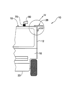
The enclosure (vehicle) 10 comprises side walls 12, rear wall 14, front
wall 16, a roof 18 and a bottom (chassis) 20. Several RPG Disruption Systems
(RDS) according to the invention, generally designated 26, are fitted on the
vehicle, the structure of which will become apparent hereinafter. The RDS 26
are
detachably fixed to the vehicle, typically to frame elements (structure beams)
thereof, by bolts 28 or other fasteners, as illustrated in Figs. 4A and 4B.
Other
arrangements are possible to. For example, the RDS may be easily
attachable/detachable or even collapsible, whereby the system is rapidly
mounted
and deployed into an operative state, whilst may be easily removed (or
collapsed/folded) so as to facilitate easy maneuvering of a vehicle in tight
areas,
such as in alleys.
CA 02737024 2011-03-11
WO 2010/029530 PCT/1L2009/000702
- 8 -
In the particular discussed embodiment the RDS 26 are fixed to the
vehicle 10 at its top, above front door 30A passenger door 30B and rear door
(not
seen), in manner so as not to obstacle the doors or constitute any other
disturbance to the operation of the vehicle or comfort of its passengers. As
will
be discussed hereinafter with reference to Figs. 6A to 6C, the RDS may be
otherwise attached to the enclosure.
The RDS 26 are independent modules, easily mounted and detached for
maintenance, replacement, etc.
As can best be seen in Figs. 4A and 4B, each RDS module 26 comprises a
housing 40 fitted with attachment portions in the form of two flanges 42 and
44,
designed for attaching to a wall of an enclosure. Thus, these flanges may
assume
other configurations depending on the intended enclosure. The RDS modules are
parallely attached to the respective walls of the enclosure.
The RDS module 26 is made of rigid material such as metal and is formed
with an inverted trough-like anvil portion 46 accommodating a downwardly
facing disrupting element 48 secures within the anvil 46 by shims 52.
Intermediate the anvil 46 and the disrupting element there is a propelling
mechanism designated 56 which in the present example is an amount of
explosive material fitted with a detonator 61. It is seen that the disrupting
element is secured at a plane substantially parallel to the respective wall,
such
that upon propelling (Figs. 5C and 5D) it maintains its parallel position,
i.e.
remains at a substantially fixed distance from the wall. Likewise, the
propelling
mechanism is so designed as to propel the disrupting element 48 substantially
parallel to the anvil 46. Thus, explosive 56 is homogeneously distributed
along
the anvil 46. Where a mechanical spring is used, this result is taken care of
as
well, as will be discussed herein after with reference to Figs. 7A to 7C.
As can further be noted in Figs. 1, 2 and 6, the vehicle/enclosure 10 is also
fitted with an early detection sensor in the form of radar 60 for initiating
the
system upon launch of an RPG. Such a sensor may be of known design, for
example a thermal detector, flare detector, blast detector, image detector,
etc.,
whereby upon detection of a launched/approaching RPG the system is armed and
CA 02737024 2011-03-11
WO 2010/029530 PCT/1L2009/000702
- 9 -
is ready to handle the threat. Several such sensors may be provided, each
facing a
different sector, or the sensor may be suited for 3600 coverage. Otherwise,
the
RPG Disruption System (RDS) may be manually initiated (e.g. by a commander
of a vehicle) or it may normally set to an initiated, active state. The sensor
60
allows for the system to be maintained at a hibernating state until detection
of the
launch or approach of an RPG threat. This renders the system safer.
In addition, the system is fitted with a detection system e.g. defining an
imaginary plane (69 in Fig. 5A) covered by the disrupting element 48, for
generating an activating signal to instantaneously propel the disrupting
element.
The detection system in Figs. 2 and 4A is in the form of an electronic curtain
created by detectors 70, namely optic sensor, magnetic sensor, RF sensors and
the like. Such sensors may be located at other locations too, e.g. opposite
the
module 26, etc. The detection system may also be in the form of a mechanical
barrier defining said imaginary plane, e.g. a fine mesh (69 in Figs. 5A ¨ 5D),
a
web or grid, whereupon tension or pressure applied to said material, or
piercing
same, generates the activating signal. The material may be in the form of a
sheet
of material embedded with or made of conductive material or coating (e.g.
special paints), etc.
A controller (microprocessor) 75 (Figs. 1 and 2) is provided for
coordinating and processing the signals received from the early sensor 60, the
imaginary plane penetration detection system and generating a propelling
signal
to timely propel the disrupting element 48 so as to anticipate the upcoming
RPG
threat. The controller is also competent for performing periodic or on-demand
tests of the system and for minimizing the chance of false alert of the
different
detectors. Also, the controller is associated with safety parameters of the
system,
e.g. the system can not be operated when the doors of a vehicle fitted with
same
are open, etc.
An example is provided for understanding the principle of the present
invention, further attention is directed to Fig. 3A illustrating a sectioned
isometric view of a typical RPG warhead generally designated 80. The warhead
is a shaped charge comprising a cylinder of explosive 82 with a metal-lined
CA 02737024 2011-03-11
WO 2010/029530 PCT/1L2009/000702
- 10 -
conical hollow (liner) 84, an inner metal envelope cone 86 which together
constitute a hollow space 88, a detonator 94 in conjunction with the explosive
82,
said detonator 94 being electrically coupled to a Piezo-electric sensor 98 at
a fore
end of the warhead via a conductive aerodynamic cover 90 and the inner metal
envelope cone 86.
Upon impact of the Piezo-electric sensor 98 with a target, an electric
current generates and is conducted via the conductive aerodynamic cover 90 and
said inner metal envelope cone 86 and said liner 84 to ignite the detonator 94
resulting in detonation of the explosive 82. Accordingly, disabling/truncating
the
Piezo-electric sensor 98 (Fig. 3B) or creating an electric shortcut between
the
aerodynamic cover 90 and the inner metal envelope cone 86 (by their
deformation so as to engage with one another; Fig. 3C) will result in failure
of
the detonator 94 to ignite and the explosive charge 82 from exploding. It
should
be noted that in some case rather than liner and envelope conducting element,
electric conductivity is by means of wiring.
In operation, when an enclosure (a vehicle in the present example) is fitted
with an RDS system according to the present invention, the system (controller
75) is set to an 'on' position and upon entry of the vehicle 10 into a hostile
arena
the early detection sensor 60 is activated. Detection of a launch of an RPG or
its
approach will arm the system (Fig. 5A), anticipating the nearing RPG threat.
At
the instance of penetration of the fore end of the warhead 80 of the RPG (i.e.
the
Piezo-electric sensor 98) into the imaginary plane 69 (Fig. 5B), the detectors
70
generate a signal to the controller 75 which in turn generates a propelling
signal
to instantly propel the disrupting element 48 by igniting the explosive
material 56
(Fig. 5C) to strike against the warhead 80, resulting in disabling/truncating
the
Piezo-electric sensor 98 or creating an electric shortcut between the
aerodynamic
cover 90 and the inner metal envelope cone 86 (Fig. 5D), resulting in failure
of
the detonator 94 to ignite and the explosive charge 82 from exploding.
RPGs in the arena typically fly at substantially low speeds, thus propelling
the disrupting element 48 at substantially high speed, whereby a module
according to the present invention may be fitted adjacent (in close proximity)
to
CA 02737024 2011-03-11
WO 2010/029530 PCT/1L2009/000702
- 11 -
the wall of the enclosure to be protected, whereby the overall dimensions of
the
enclosure are less effected.
Furthermore, by propelling the disrupting element 48 at a substantially
high speed, the RPG threat becomes neutralized by preventing initiation of the
explosive material (as opposed to deflecting or breaking the threat). This
takes
place, as explained herein above, by disrupting the electric initializing of
the
explosive either by breaking or truncating the Piezo-electric sensor from the
RPG
or by causing an electric shortcut by deforming the aerodynamic cover 90 and
the
inner metal envelope cone 86. Accordingly, there is no need for high momentum
of the disrupting element.
Turning now to Figs. 6A to 6C there are illustrated exemplary
configurations of fitting a vehicle with RDS according to the present
invention.
In Fig. 6A the vehicle 100 is fitted with a front RDS module 102 fitted at a
front
edge of the front door 104 and another RDS 108 fitted at a rear end of the
vehicle, behind the rear door 110, whereby the RDS 102 and 108 are
substantially vertical and face one another with a rear of the vehicle
protected by
a horizontally extending RDS 114 at a top end thereof. In the example of Fig.
6B
the RDS 116 and 118 extend vertically at a center of the vehicle 120, in a
back-
to-back orientation, such that rear RDS 116 covers the rear door portion and
the
front RDS 118 covers the front of the vehicle, respectively. Fig. 6C
illustrates an
alternative embodiment for protecting a vehicle 123, comprising a front bottom
RDS124, a front top RDS 126, a rear bottom RDS 128 and a rear top RDS 130,
respectively mounted on the front door 134 and the rear door 136.
Figs. 7A to 7C illustrate alternative modifications of propelling
mechanisms for propelling of the disrupting element 48. In Fig. 7A the
explosive
charge is replaced by an array of compression springs 146 maintained at their
normally compressed state, whereby upon retraction of several retention pins
148
(e.g. by a solenoid) the springs 146 expand so as to propel the disrupting
element
48. In Fig. 7B the propelling mechanism is in the form of a 'magnetic spring'
composed of one or more magnets 150 with their polarity opposite that of the
disrupting element 48. The magnets may be permanent magnets (in which case
CA 02737024 2011-03-11
WO 2010/029530 PCT/1L2009/000702
- 12 -
the disrupting element is retained by a mechanical arresting arrangement as
discussed hereinbefore), or charged per demand, i.e. an array of coils is
provided
(not shown) for generating a powerful magnetic field with directional
orientation
so as to propel the disrupting element. In Fig. 7C the propelling mechanism is
in
the form of a pneumatic spring comprising one or more compressed gas cylinders
156, with the disrupting element 48 retained within the anvil portion 46 of
the
housing 40 by retention pins (not seen), whereby rapid discharge of the high-
pressurized gas entails rapid propelling of the disrupting element, with
tear/break
of the retention pins.
Turning now to Figs. 8A to 8F there are illustrated exemplary cross
sections of disrupting elements designated 48a to 48f, respectively, useful in
a
system according to the present invention, these being examples only.
Those skilled in the art to which this invention pertains will readily
appreciate that numerous changes, variations, and modifications can be made
without departing from the scope of the invention, mutatis mutandis.