Note: Descriptions are shown in the official language in which they were submitted.
CA 02737221 2011-03-14
WO 2010/030426 PCT/US2009/047830
OSTOMY POUCH
Field of the Disclosure
100011 The present disclosure is generally directed to a pouch which is
suitable for
the collection of a liquid or semisolid body waste material and, more
particularly, to an
ostomy pouch which is adapted to receive such body waste material through a
stomal opening
for later disposal.
Background of the Disclosure
100021 Ostomy pouches for the collection of liquid or semisolid body waste
material are well known and typically include flat, opposing side walls
secured together along
their edges to define a human stomal discharge collection cavity. One of the
side walls is
provided with an opening to receive a stoma, and means such as a connecting
flange is
provided for securing the pouch to an adhesive barrier placed to surround the
stoma so that
body waste material discharged through the stoma will be received within the
cavity. At its
lower end, the ostomy pouch may have a discharge opening which may be closed
during
collection of the liquid or semisolid body waste material that passes through
the stoma but
may be opened for draining the body waste material from the pouch after a
period of use.
Alternatively, the ostomy pouch may be designed for a single use in which case
it will not be
provided with a discharge opening since the entire pouch will be discarded
after it has
substantially filled with human stoma! discharge.
100031 A drainable pouch is typically reusable following periodic emptying of
the
body waste material by utilizing a closure for the discharge opening that may
take a number
of different forms so long as it serves to prevent leakage of the body waste
material whereas
there is no need for a closure in the case of a single use pouch since it is
intended to be
discarded following use.
[0004] In either case, it is known that ostomy pouches often show bulkiness
after a
period of time of accumulating body waste material. This is true with respect
to both liquid
and semisolid body waste material because the normally flat side walls of such
pouches are
formed of a very thin film which easily expands outwardly. It is also known
that ostomy
pouches are sized to accommodate a certain period of use which makes it
difficult to conceal
them beneath clothing even before they fill with body waste material. However,
after ostomy
pouches do fill with human stomal discharge, they can expand outward
significantly to create
an obvious bulge.
CA 02737221 2011-03-14
WO 2010/030426 PCT/US2009/047830
10005] While the foregoing is true for both drainable ostomy pouches and
single
use ostomy pouches, there is still an additional important consideration. A
manufacturer of
ostomy products commonly has a high number of SKUs devoted to its ostomy
product
portfolio due to the differing requirements in terms of size and capacity for
those who need to
use ostomy pouches for collection of human stomal discharge. If the number of
SKUs could
be reduced, it would be of great benefit to both the manufacturers and the
users of ostomy
pouches.
100061 In particular, a reduction in the number of SKUs would reduce the cost
of
manufacturing, marketing and selling ostomy pouches which would result in a
reduction of
the cost of ostomy pouches to the user. As a result, there has been a need to
address the
desire to have ostomy pouches that are more easily concealed beneath clothing
as well as the
desire to reduce the number of SKUs for ostomy pouches.
Summary of the Disclosure
100071 The present disclosure is directed to an ostomy pouch comprised of
proximal and distal side walls of flexible sheet material joined together
along their peripheral
edges to define a cavity therebetween. The side walls are also joined in at
least one location
inwardly of the peripheral edges to limit separation of the proximal and
distal side walls.
With this construction, the side walls also include a laterally outwardly
expandable fold
which is formed by at least a portion of at least one of the side walls.
100081 In one embodiment, the peripheral edges of the proximal and distal side
walls are joined together by welding or the like. Similarly, the side walls
may also be joined
at the at least one location inwardly of the peripheral edges by welding.
Alternatively, the
proximal and distal side walls may be joined at the at least one location
inwardly of the
peripheral edges by a baffle.
[0009] In the alternative utilizing a baffle, the baffle may have
proximal and distal
ends secured to the proximal and distal side walls by welding or the like in
order to thereby
limit the separation of the proximal and distal side walls.
100101 In another embodiment, the proximal and distal side walls may be joined
by
welding or the like at a plurality of locations inwardly of the peripheral
edges in order to
thereby limit the separation of the proximal and distal side walls.
2
CA 02737221 2011-03-14
WO 2010/030426 PCT/US2009/047830
100111 In yet another embodiment, the laterally outwardly expandable
fold is
formed by substantially the entirety of the joined peripheral edges. Further,
the ostomy
pouch may be formed to have a top edge, a bottom edge and opposite side edges
extending
between the top edge and the bottom edge. In this case, a laterally outwardly
expandable fold
may suitably be formed along each of the opposite side edges of the ostomy
pouch.
[0012] In still another embodiment, the ostomy pouch may be generally
rectangular
in shape and the opposite sides may be generally parallel such that the
laterally outwardly
expandable folds are generally parallel. With a generally rectangular shaped
ostomy pouch,
it may also include a generally parallel top and bottom in which case a
laterally outwardly
expandable fold may be formed in at least the bottom of the pouch.
[0013] Still additionally, in connection with all of the embodiments,
the laterally
outwardly expandable fold(s) may each be secured by an adhesive spot weld
which is subject
to degradation from exposure to human stomal discharge in the cavity of the
ostomy pouch.
100141 Other advantages and features of the present disclosure will become
apparent from the following specification taken in conjunction with the
accompanying
drawings.
Brief Description of the Drawings
[00151 Figure 1 is a front elevational view of a first embodiment of an ostomy
pouch in accordance with the present disclosure;
[0016] Figure 2 is a cross-sectional view taken along the line 2-2 of Figure 1
illustrating the side walls joined together at a point inwardly of the
peripheral edges;
[0017] Figure 3 is a view similar to Figure 2 illustrating a fold expanded
laterally
outwardly to accommodate an additional volume of human stoma! discharge;
100181 Figures 4A-4C are cross-sectional views illustrating various additional
laterally outwardly expandable folds before and after expansion thereof;
[0019] Figure 5 is a front elevational view of a second embodiment of an
ostomy
pouch in accordance with the present disclosure;
100201 Figure 6 is a cross-sectional view taken along the line 6-6 of Figure 5
illustrating a laterally outwardly expandable fold before expansion thereof;
3
CA 02737221 2011-03-14
WO 2010/030426 PCT/US2009/047830
100211 Figure 7 is a front elevational view of Figure 5 with folds
expanded laterally
outwardly to accommodate an additional volume of human stomal discharge;
[00221 Figure 8 is a cross-sectional view taken along the line 8-8 of Figure 7
illustrating a laterally outwardly expandable fold after expansion thereof;
and
[0023] Figure 9 is a front elevational view of a third embodiment of an ostomy
pouch in accordance with the present disclosure.
Detailed Description of the Present Disclosure
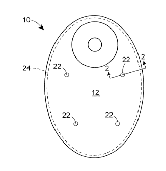
[0024] In the various illustrations given, and with reference first to
Figures 1-3, a
first embodiment of an ostomy pouch according to the present disclosure is
generally
designated by the reference 10. The ostomy pouch 10 is formed of a proximal
side wall 12
and a distal side wall 14 of flexible sheet material which are joined together
along their
peripheral edges 16 and 18, respectively, to define a cavity 20 for receiving
human stomal
discharge. In addition, the side walls 12 and 14 are also joined in at least
one location such as
22 inwardly of the peripheral edges 16 and 18 to thereby limit the separation
of the proximal
and distal side walls 12 and 14.
100251 Referring to Figures 2 and 3, it will be seen that the side walls 12
and 14
include a laterally outwardly expandable fold 24 formed by at least a portion
of the joined
peripheral edges 16 and 18 thereof. The peripheral edges 16 and 18 of the
proximal and
distal side walls 12 and 14 may be joined together by welding as at 26 as best
shown in
Figure 3. As shown in Figures 2 and 3, the proximal and distal side walls 12
and 14 also may
be joined together by welding or the like as at 22 to thereby limit the extent
to which they
may separate from one another.
[0026] As an alternative illustrated in Figures 2A and 3A, the proximal and
distal
side walls 12 and 14 may be joined together at one or more locations such as
22' inwardly of
the peripheral edges 16 and 18 by a baffle 28. The baffle 28 may be z-shaped
and secured to
the proximal and distal side walls 12 and 14 as at 30 and 32 to limit
separation thereof. In
particular, the baffle 28 may have a central web 34 extending between a
proximal end portion
36 welded to the proximal side wall 12 as at 30 and a distal end portion 38
welded to the
distal sidewall 14 as at 32 .
4
CA 02737221 2011-03-14
WO 2010/030426 PCT/US2009/047830
[00271 Regardless of whether the proximal and distal side walls 12 and 14 are
joined together by welding, adhesive, or baffles, it may be desirable
depending upon the size
of the ostomy pouch 10 for the proximal and distal side walls 12 and 14 to be
joined together
at a plurality of locations such as 22 inwardly of the peripheral edges 16 and
18 as shown in
Figure 1.
[0028] Still referring to Figure 1, it will be seen that the laterally
outwardly
expandable fold 24 is formed by substantially the entirety of the peripheral
edges 16 and 18
of the proximal and distal side walls 12 and 14 of the ostomy pouch 10. By
providing the
laterally outwardly expandable fold 24 entirely about the perimeter of the
ostomy pouch 10, it
will be appreciated that it is possible to manufacture the pouch in a smaller
size than
conventional pouches while not reducing the overall capacity of the cavity 20
to hold human
stomal discharge since the cavity 20 can expand to a considerable degree.
Specifically, the
laterally outwardly expandable fold 24 can expand entirely about the perimeter
of the ostomy
pouch 10 and, depending upon the form of the fold 24, the additional capacity
of the cavity
20 can be increased significantly.
[0029] Referring to Figures 2 and 3, it will be seen that the laterally
outwardly
expandable fold 24 is comprised of a single inwardly directed fold wherein the
outermost
extremes of the proximal and distal side walls 12 and 14 where the peripheral
edges 16 and
18 are welded as at 26 initially point inwardly of the cavity 20. However, it
is also possible
to form the laterally outwardly expandable fold so it comprises a double fold
such as the folds
24', 24" and 24" which are shown in Figures 4A, 4B and 4C. As will be
appreciated, the
double folds 24', 24" and 24" each include a pair of inwardly directed folds
24a' and 24b',
24a" and 24b", and 24a" and 24b" as well as a single outwardly directed fold
24c', 24c"
and 24c" which points outwardly of the cavity 20 both before and after the
fold expands
outwardly.
CA 02737221 2011-03-14
WO 2010/030426 PCT/US2009/047830
100301 To understand the laterally outwardly expandable folds 24', 24" and
24",
the folds have been shown in Figures 4A, 4B and 4C in solid lines where the
cavity 20 as an
initial capacity for receiving human stomal discharge. The folds 24', 24" and
24" have also
been shown in Figures 4A, 4B and 4C in dashed lines where the cavity 20 has a
maximum
capacity for receiving human stomal discharge after the ostomy pouch 10 has
been used for a
time during which the cavity 20 has filled beyond its initial capacity. By
utilizing any one of
the double folds 24', 24" and 24", it is possible to enhance the maximum
capacity of the
cavity 20 receiving human stomal discharge beyond what can be achieved with
the single
fold 24.
100311 Referring now to Figures 5-8, a second embodiment of an ostomy pouch
according to the present disclosure generally designated by the reference 100
is formed of a
proximal side wall 112 and a distal side wall 114 of flexible sheet material.
The side walls
112 and 114 are joined together as by welding or the like along their
peripheral edges 116
and 118, respectively, to define a cavity 120 for receiving human stomal
discharge and, in
this embodiment, the side walls 112 and 114 are shaped such that the ostomy
pouch 100 has a
top edge 140, a bottom edge 142, and a pair of opposite side edges 144 and
146. Also, the
side walls 112 and 114 are joined in one or more locations such as 122
inwardly of the
peripheral edges 116 and 118 to thereby limit the amount by which the proximal
and distal
side walls 112 and 114 may separate from one another.
100321 Referring to Figures 5 and 7, it will be seen that the side walls 112
and 114
include a laterally outwardly expandable fold 124 formed along each of the
opposite side
edges 144 and 146 of the ostomy pouch 100. The peripheral edges 116 and 118 of
the side
walls 112 and 114 may be joined together by welding as at 126 as best shown in
Figure 8. As
shown in Figures 6 and 8, the proximal and distal side walls 112 and 114 may
also be joined
together by welding or the like as at 122 to thereby limit the extent to which
they may
separate from one another.
[0033J Referring now to Figure 9, a third embodiment of an ostomy pouch
according to the present disclosure generally designated by the reference
numeral 200 is
formed of a proximal side wall 212 and a distal side wall 214 of flexible
sheet material. The
side walls 212 and 214 are joined together by welding or the like along
peripheral edges 216
and 218, respectively, to define a cavity 220 for receiving human stomal
discharge and, in
this embodiment, the side walls 212 and 214 are generally rectangular so the
ostomy pouch
200 has a top edge 240, a bottom edge 242, and parallel side edges 244 and
246. Also, the
6
CA 02737221 2014-04-08
side walls 212 and 214 are joined in one or more locations such as 222
inwardly of the
peripheral edges 216 and 218 to thereby limit the amount by which the proximal
and distal
side walls 212 and 214 may separate from one another.
[0034] As shown in Figure 9, it will be seen that the side walls 212 and 214
include
laterally outwardly expandable folds 224 which are formed by inward folding of
the side wall
212 of the ostomy pouch 200. The peripheral edges 216 and 218 of the side
walls 212 and 214
may be joined together by welding as was described for the other embodiments.
As also shown
in Figure 9, the ostomy pouch 200 may have not only the outwardly expandable
folds 224, but
also at least one additional outwardly expandable fold 224a along the bottom
edge 242.
[0035] In addition, the laterally outwardly expandable folds 224 and 224a may
each be
secured by one or more adhesive spot welds as at 248 which are subject to
degradation from
exposure to human stomal discharge in the cavity 220.
[0036] While in the foregoing there have been set forth representative
embodiments of
the present disclosure, it will be appreciated that the details herein given
may be varied by
those skilled in the art without departing from the scope of the appended
claims, which should
not be limited by particular examples set forth herein but should be construed
in a manner
consistent with the description as a whole. For example, a single piece of
flexible sheet
material may be used to form the side walls of an ostomy pouch, or
alternatively, two or more
separate pieces of flexible sheet material may be used to form the side walls
of an ostomy
pouch, in accordance with the disclosure.
7