Note: Descriptions are shown in the official language in which they were submitted.
CA 02737322 2011-04-14
ROTARY UNITS, ROTARY MECHANISMS, AND RELATED APPLICATIONS
FIELD OF THE INVENTION
[0001] The invention relates generally to mechanical, electrical, or
electromechanical devices, and
provides rotary units, rotary mechanisms, methods, and related devices and
other applications that are
useful for a wide variety of purposes.
BACKGROUND OF THE INVENTION
[0002] Electromechanical devices are ubiquitous. Some of these devices include
rotating components
and are used in many different applications. Gardening tools such as rotor
tillers, for example, typically
include rotating rotors having tines, which contact the soil during operation.
Many other devices of use in
agricultural and construction, among many other fields or applications also
utilize various types of
rotational components to achieve desired forms of work.
SUMMARY OF THE INVENTION
[0003] The invention relates to rotary units and rotary mechanisms that are
suitable for use in numerous
applications. Rotary units typically include rotational components that are
configured to rotate. In some
embodiments, for example, multiple rotary units are assembled in rotary
mechanisms such that
neighboring pairs of rotational components counter-rotate or contra-rotate
relative to one another during
operation of the rotary mechanisms. Rotational components generally include
one or more implements
that are structured to perform or effect one or more types of work as the
rotational components rotate
relative to one another in a given rotary mechanism. In certain embodiments,
implements are configured
to rotate and/or to effect the movement of other components as rotational
components rotate. These and
many other aspects will be apparent upon a complete review of this disclose.
[0004] In one aspect, the invention provides a rotary unit that includes at
least one rotational component
comprising at least a first gear component, at least one gear structure
receiving area that is configured to
receive one or more gear structures or components thereof, and at least a
second gear component disposed
at least proximal to the gear structure receiving area. The rotary unit also
includes at least one gear
structure comprising at least one support component and at least one third
gear component rotatably
coupled to the support component. The third gear component is configured to
operably engage the
second gear component when the gear structure is at least partially disposed
in the gear structure receiving
area. In addition, the first gear component is configured to operably engage
one or more third gear
1
CA 02737322 2011-04-14
components of at least one other rotary unit when the rotary unit is disposed
proximal to the other rotary
unit. In some embodiments of the rotary units of the invention, the rotational
component is configured to
receive at least one drive mechanism or a portion thereof. In certain
embodiments, the other rotary unit
operably engages the rotary unit. To further illustrate, in certain
embodiments, at least two other rotary
units operably engage the rotary unit.
[0005] Typically, the rotary units or mechanisms of the invention include one
or more implements that
can be used or adapted for use in many different applications. In certain
embodiments, for example, at
least one surface of a rotational component comprises at least one implement.
Optionally, a rotational
component comprises at least one implement that is configured to effect the
movement of one or more
other components (e.g., a propeller component or the like) when the rotational
component rotates and the
implement operably engages the other components. In certain embodiments,
rotary units or mechanisms
include at least one implement rotatably coupled to a rotation component,
which implement is configured
to operably engage one or more gear components of one or more other rotational
components. To
illustrate, in some embodiments, the rotary units or mechanisms of the
invention include one or more gear
components that are configured to operably engage one or more implements
rotatably coupled to one or
more other rotational components. In some embodiments, a rotary unit or a
related rotary mechanism of the
invention includes at least one implement rotatably coupled to a rotational
component. In these
embodiments, the implement is optionally configured to operably engage one or
more gear components of
at least one other rotary unit when the rotary unit is disposed proximal to
the other rotary unit such that
the implement rotates when at least the rotational component and the other
rotary unit rotate relative to
one another. Optionally, at least one implement is disposed in, on and/or
extending from at least one
surface of a rotational component. In some embodiments, for example,
implements include one or more
of, e.g., a blade, a razor, a prong, a peg, a claw, a tine, a chain, a stake,
a column, a pillar, an arch, a
bracket, a gear component, a bristle, a plume, an abrasive component, an
elastomeric component, a nail
filing component, a nail buffing component, a hair cutting component, a
massaging component, a post,
etc. To further illustrate, at least a portion of an implement comprises at
least one cross-sectional shape
selected from, e.g., a circle, an oval, a square, a rectangle, a trapezoid, an
irregular n-sided polygon, a
regular n-sided polygon, and the like.
[0006] In certain embodiments, a device or vehicle includes a rotary unit or
mechanism of the invention.
In some embodiments, the device is selected from, e.g., a held-held device, a
rototiller, a hair cutting
device, a massaging device, nail grooming device, a propulsion device, a
woodworking device, a lathe, a
woodchipping device, a machining device, a dermabrasion device, a medical
device, a dental device, a
cleaning device, an engine, a snow blower, a nozzle, a food preparation
device, a grinder, a pencil
2
CA 02737322 2011-04-14
sharpener, a lawn mower, a vacuum cleaner, a hair dryer, a plumbing device, a
weapon, a surfboard, a
scuba device, a component thereof, a combination thereof, etc. In certain
embodiments, the vehicle
includes a farming vehicle, a mining vehicle, a construction vehicle, a
submarine, an aircraft, a marine
vehicle, a boat, a personal watercraft, a military vehicle, or the like.
[00071 The drive mechanisms used with the rotary units and rotary mechanisms
of the invention include
various embodiments. In certain embodiments, for example, a drive mechanism
comprises at least one
motor. Optionally, a drive mechanism comprises one or more of, e.g., a drive
shaft, a chain drive, a belt
drive, a gear drive, or the like. In some embodiments, a drive mechanism
comprises at least one flexible
drive shaft. To further illustrate, a drive mechanism is optionally operably
coupled to a counter-rotational
mechanism and/or rotational components via at least one drive shaft, at least
one drive chain, at least one
belt drive, and/or at least one gear drive.
[00081 In another aspect, the invention provides a rotary mechanism that
includes at least first, second,
and third rotational components in which at least one of the rotational
components comprises at least one
implement. The rotary mechanism also includes at least first and second
counter-rotational mechanisms
in which the first counter-rotational mechanism operably engages at least the
first and second rotational
components, and in which the second counter-rotational mechanism operably
engages at least the second
and third rotational components. In addition, the rotary mechanism also
includes at least one drive
mechanism component or a portion thereof operably engaged with one or more of
the rotational
components and/or with one or more of the counter-rotational mechanisms, which
drive mechanism
component or portion thereof is configured at least to effect rotation of the
rotational components and the
counter-rotational mechanisms such that the first and third rotational
components rotate in a first direction
and the second rotational component rotates in a second direction. Typically,
the drive mechanism
component or portion thereof is configured to effect rotation of the
rotational components and the
counter-rotational mechanisms such that the first and third rotational
components rotate in a second
direction and the second rotational component rotates in a first direction. In
some embodiments, the
rotary mechanisms of the invention include more than three rotational
components (e.g., 4, 5, 6, 7, 8, 9,
10 or more rotational components). In certain embodiments, the second
rotational component is disposed
between the first and third rotational components. Optionally, at least one of
the rotational components
comprises one or more gear components that are configured to operably engage
one or more implements
rotatably coupled to one or more other rotational components. In certain
embodiments, at least the first
counter-rotational mechanism comprises at least a first gear component
disposed on the first rotational
component, at least a second gear component disposed on the second rotational
component, and at least a
third gear component that operably engages the first and second gear
components such that when the first
3
CA 02737322 2011-04-14
gear component rotates in the first direction, the second and third gear
components rotate in the second
direction and when the first gear component rotates in the second direction,
the second and third gear
components rotate in the first direction. In some of these embodiments, the
rotary mechanism includes a
retaining mechanism that retains the third gear component operably engaged
with the first and second
gear components. In some of these embodiments, the second gear component
substantially defines a gear
receiving area that is configured to receive at least a portion of the third
gear component. Gear
components used with the rotary units, rotary mechanisms, and other
applications of the invention
typically include gear teeth. Any operable gear tooth configuration and/or
type are optionally used in the
rotary units, rotary mechanisms and applications of the invention.
[0009] In one aspect, the invention provides a rotary unit that includes at
least a first rotational
component configured to rotate around a rotational axis, which first
rotational component comprises at
least first and second surfaces. The first surface comprises one or more gear
components that are
configured to operably engage one or more gear components of at least a second
rotational component
(e.g., of a second rotary unit, etc.) when the first rotational component is
disposed proximal to the second
rotational component such that when the first rotational component rotates in
a first direction, the second
rotational component rotates in a second direction. The second surface
comprises one or more gear
components that are configured to operably engage one or more gear components
of at least a third
rotational component (e.g., of a third rotary unit, etc.) when the first
rotational component is disposed
proximal to the third rotational component such that when the first rotational
component rotates in the
first direction, the third rotational component rotates in the second
direction. In addition, at least one
surface of the first rotational component comprises at least one implement,
which surface is configured to
rotate substantially non-perpendicular to the rotational axis. In some
embodiments, the surface of the first
rotational component that comprises the implement is configured to rotate
substantially parallel to the
rotational axis. In some embodiments, the first surface comprises one or more
sun gear components. In
certain embodiments, the second surface comprises one or more ring gear
components. In some
embodiments, a rotational mechanism comprises the rotary unit. In some
embodiments, at least one of
the surfaces of the first rotational component comprises at least one friction
reducing material. In certain
of these embodiments, for example, the friction reducing material is selected
from, e.g., a coating, a
lubricant, a surface feature, a roller ball, and the like.
[0010] In another aspect, the invention provides a rotary mechanism that
includes at least two rotary
units that each comprises at least one rotational component that comprises at
least a first gear component,
and at least one second gear component configured to operably engage the first
gear component. The
rotary mechanism also includes at least one drive mechanism component or
portion thereof that operably
4
CA 02737322 2011-04-14
engages at least the second gear components of at least first and second
rotary units. The drive
mechanism component or portion thereof is configured to effect rotation of the
second gear components
such that the rotational component of the first rotary unit rotates in a first
direction and the rotational
component of the second rotary unit rotates in a second direction. In some
embodiments, the first gear
component comprises at least one ring gear component. In certain embodiments,
at least one surface of at
least one of the rotational components comprises at least one implement. In
these embodiments, the
surface is optionally configured to rotate substantially non-perpendicular to
a rotational axis of the
rotational components. In other of these embodiments, the surface is
optionally configured to rotate
substantially parallel to a rotational axis of the rotational components. In
some embodiments, the rotary
mechanism includes at least one positioning component that is configured to
position the rotary units
relative to one another. In some of these embodiments, the positioning
component comprises a frame
structure. Optionally, at least one surface of the positioning component
comprises at least one friction
reducing material.
[0011] In another aspect, the invention provides a rotary mechanism that
includes at least two rotary
units that each comprise at least one rotational component that comprises at
least one sun gear component
and at least one ring gear component, and at least one gear structure that
comprises at least one support
component and at least one planetary gear component rotatably coupled to the
support component. The
planetary gear component is configured to operably engage the ring gear
component. In addition, the sun
gear component of at least a first rotary unit operably engages the planetary
gear component of at least a
second rotary unit such that when the rotational component of the first rotary
unit rotates in a first
direction, the rotational component of the second rotary unit rotates in a
second direction. In some
embodiments, the gear structure of the first rotary unit is operably connected
to the gear structure of the
second rotary unit such that the support components are substantially fixedly
positioned relative to one
another at least when the rotational component of the first rotary unit
rotates in the first direction, the
rotational component of the second rotary unit rotates in the second
direction. Typically, at least one of
the rotational components comprises at least one implement. In some
embodiments, at least two of the
rotational components are non-concentrically disposed relative to one another.
In some embodiments, the
rotary mechanism includes at least three, at least four, at least five, at
least six, at least seven, at least
eight, at least nine, at least ten, or more rotary units.
[0012] In another aspect, the rotational mechanism includes at least a first
rotary unit that comprises at
least one rotational component that comprises at least first and second sun
gear components. The
rotational mechanism also includes at least a second rotary unit that
comprises at least one rotational
component that comprises at least first and second ring gear components. In
addition, the rotational
5
CA 02737322 2011-04-14
mechanism also includes at least a first planetary gear component that is
configured to operably engage
the second sun gear component of the first rotary unit and the first ring gear
component of the second
rotary unit such that when the rotational component of the first rotary unit
rotates in a first direction, the
rotational component of the second rotary unit rotates in a second direction.
[0013] In some embodiments, the rotational components of the first and second
rotary units are
configured to rotate at different rates relative to one another. In some
embodiments, the rotational
mechanism includes at least one gear structure that comprises at least one
support component in which the
first planetary gear component is rotatably coupled to the support component.
In certain embodiments,
the rotational mechanism includes at least a second planetary gear component
that is configured to
operably engage one or more gear components of at least a third rotary unit
and the second ring gear
component of the second rotary unit such that when the rotational component of
the second rotary unit
rotates in the second direction, a rotational component of the third rotary
unit rotates in the first direction.
[0014] In some embodiments, the first sun gear component of the first rotary
unit is configured to
operably engage one or more gear components of at least a fourth rotary unit
such that when the rotational
component of the first rotary unit rotates in the first direction, a
rotational component of the fourth rotary
unit rotates in the second direction. In some of these embodiments, the first
sun gear component of the
first rotary unit is configured to operably engage the one or more gear
components of the fourth rotary
unit via one or more planetary gear components.
[0015] In certain embodiments, the rotational mechanism includes more than two
rotary units. In some
of these embodiments, a sum of rotational rates of the rotational components
of a first pair of neighboring
rotary units is configured to be substantially identical to a sum of
rotational rates of the rotational
components of a second pair of neighboring rotary units when the rotational
components rotate relative to
one another.
[0016] In another aspect, the invention provide a cleaning device that
includes at least one head
component that comprises at least one cleaning material support component and
at least one cleaning
surface component. In some embodiments, the cleaning surface component
comprises at least one
elevational element. The cleaning material support component comprises at
least one cleaning material
support component surface that at least partially defines at least one
cleaning material cartridge receiving
area. The cleaning material support component comprises at least one opening
such that the cleaning
material cartridge receiving area communicates with the cleaning surface
component. In addition, the
cleaning material cartridge receiving area is configured to receive at least
one cleaning material cartridge
comprising cleaning material such that at least a portion of the cleaning
material is movable to and/or
6
CA 02737322 2011-04-14
from the cleaning material cartridge receiving area to extend over at least a
portion of the cleaning surface
component when the cleaning material cartridge is at least partially disposed
in the cleaning material
cartridge receiving area. The cleaning device also includes at least one
rotary mechanism comprising at
least one rotational component that comprises at least one implement.
[00171 In some embodiments, the rotary mechanism of the cleaning device
comprises at least first,
second, and third rotational components. In these embodiments, the rotary
mechanism also includes at
least first and second counter-rotational mechanisms. The first counter-
rotational mechanism operably
engages at least the first and second rotational components. The second
counter-rotational mechanism
operably engages at least the second and third rotational components. In these
embodiments, the rotary
mechanism also includes at least one drive mechanism component or a portion
thereof operably engaged
with one or more of the rotational components and/or with one or more of the
counter-rotational
mechanisms, which drive mechanism component or portion thereof is configured
at least to effect rotation
of the rotational components and the counter-rotational mechanisms such that
the first and third rotational
components rotate in a first direction and the second rotational component
rotates in a second direction.
In some of these embodiments, the implement comprises a plurality of bristles.
[00181 In some embodiments, the cleaning device includes at least one
positioning mechanism
component that is configured to selectively position the cleaning material at
least relative to the cleaning
material support component when the cleaning material cartridge is at least
partially disposed in the
cleaning material cartridge receiving area. In some embodiments, the cleaning
device includes at least
two cleaning material support components that are each configured to receive
at least a component of the
cleaning material cartridge. In some embodiments, the cleaning device includes
at least one retaining
component that is configured to substantially retain the cleaning material
cartridge at a selected position
relative to the cleaning material support component when the cleaning material
cartridge is at least
partially disposed in the cleaning material cartridge receiving area. In some
embodiments, the cleaning
device includes at least one retaining mechanism that is configured to
substantially retain the cleaning
material at a selected position relative to the cleaning surface component
when the cleaning material
cartridge is at least partially disposed in the cleaning material cartridge
receiving area and the cleaning
material extends over at least the portion of the cleaning surface component.
In some embodiments, the
cleaning device includes the cleaning material cartridge at least partially
disposed in the cleaning material
cartridge receiving area of the cleaning material support component. In some
embodiments, the cleaning
device includes at least one handle operably connected to the head component.
In some of these
embodiments, the handle is pivotally connected to the head component via at
least one pivot mechanism.
7
CA 02737322 2011-04-14
[0019] In some embodiments, the cleaning device includes at least one
conveyance mechanism, or at
least one component thereof, that is configured to convey at least the
cleaning material over at least the
portion of the cleaning surface component when the cleaning material cartridge
is at least partially
disposed in the cleaning material cartridge receiving area. In some
embodiments, the conveyance
mechanism is manually operated via at least one manual conveyance component.
In some embodiments,
the conveyance mechanism or the component thereof is configured to operably
engage the cleaning
material cartridge to effect conveyance of the cleaning material when the
cleaning material cartridge is at
least partially disposed in the cleaning material cartridge receiving area. In
some embodiments, the
conveyance mechanism is configured to convey the cleaning material at least
one selected incremental
distance. In some embodiments, the conveyance mechanism comprises one or more
gear components. In
some embodiments, the conveyance mechanism comprises at least one motor.
component that is
configured to effect conveyance of the cleaning material when the cleaning
material cartridge is at least
partially disposed in the cleaning material cartridge receiving area.
[0020] In some embodiments, the cleaning device includes at least one fluid
handling mechanism or at
least one component thereof that is configured to convey at least one fluid
from at least one fluid source
to at least one fluid outlet. In some embodiments, the fluid outlet
communicates with the cleaning
material cartridge or a portion thereof when the cleaning material cartridge
is at least partially disposed in
the cleaning material cartridge receiving area. In some embodiments, the fluid
outlet is disposed
proximal to at least one surface of the head component. In some embodiments,
the fluid outlet comprises
at least one nozzle. In some embodiments, the fluid handling mechanism
comprises at least one pumping
mechanism that is configured to pump the fluid from the fluid source to the
fluid outlet. In some
embodiments, the fluid handling mechanism comprises at least one vaporization
component that is
configured to vaporize the fluid at least proximal to the fluid outlet. In
some embodiments, the fluid
source and fluid outlet communicate via at least one fluid conduit. In some
embodiments, the fluid source
comprises at least one fluid container. In some of these embodiments, the
fluid container is removable.
[0021] In another aspect, the invention provides a device that includes at
least two rotational units, and at
least one rotary mechanism configured to operably engage at least one of the
rotational units to effect
counter-rotation of neighboring pairs of the rotational units. In some
embodiments, at least one of the
rotational units comprises at least one propeller unit.
[0022] In another aspect, the invention provides a device that includes at
least two rotational units in
which at least one of the rotational units comprises at least one implement
and at least one gear
component, and at least one rotary mechanism that operably engages the gear
component such that when
9
CA 02737322 2011-04-14
the rotary mechanism rotates, neighboring pairs of rotational units counter-
rotate relative to one another.
In some embodiments, the device includes at least three, at least four, at
least five, at least six, at least
seven, at least eight, at least nine, at least ten, or more rotational units.
In certain embodiments, the
implement comprises at least one propeller component. In some embodiments, at
least one surface of the
at least one rotational unit comprises the gear component, which surface is
configured to rotate
substantially non-perpendicular to a rotational axis of the rotational units
and/or the rotary mechanism. In
certain embodiments, the gear component is disposed at least partially around
the implement. In some
embodiments, the rotary mechanism comprises at least two rotary units that
operably engage gear
components of different rotational units in which the rotary units are
configured to counter-rotate relative
to one another. In some embodiments, at least one of the rotational units
and/or the rotary mechanism
comprises at least one rotational alignment component. In certain embodiments,
the device includes at
least one drive mechanism operably connected to the rotational units and/or to
the rotary mechanism. In
some embodiments, the device includes at least one positioning component
(e.g., a housing, a frame
structure, or the like) configured to position the rotational units and the
rotary mechanism relative to one
another. In some embodiments, the device includes at least two rotary
mechanisms, wherein at least a
first rotary mechanism operably engages the gear component of at least a first
rotational unit, wherein at
least a second rotary mechanism operably engages the gear component of at
least a second rotational unit,
and wherein the first rotary mechanism is configured to rotate in at least a
first direction and the second
rotary mechanism is configured to rotate in at least a second direction such
that when the first and second
rotary mechanisms rotate, the first rotational unit rotates in the first
direction and the second rotational
unit rotates in the second direction. In some of these embodiments, the first
rotary mechanism operably
engages the gear components of at least a first set of non-neighboring
rotational units and wherein the
second rotary mechanism operably engages the gear components of at least a
second set of non-
neighboring rotational units.
[00231 In another aspect, the invention provides a cleaning device that
includes at least one rotary
mechanism that comprises at least two rotational components that are non-
concentrically disposed relative
to one another and are configured to counter-rotate relative to one another
around a rotational axis in
which at least one surface of at least one of the rotational components
comprises at least one implement
(e.g., bristles or the like), which surface is configured to rotate
substantially non-perpendicular to the
rotational axis. In some embodiments, the rotary mechanism comprises at least
three, at least four, at
least five, at least six, at least seven, at least eight, at least nine, at
least ten, or more rotational
components. In some embodiments, the cleaning device includes at least one
head component in which
9
CA 02737322 2011-04-14
the rotary mechanism is at least partially disposed within the head component.
Optionally, at least one
handle is operably connected to the head component.
[0024] In some embodiments, the cleaning device includes at least one fluid
handling mechanism or at
least one component thereof that is configured to convey at least one fluid
from at least one fluid source
to at least one fluid outlet. In certain embodiments, the fluid outlet is
disposed proximal to at least one
surface of a head component. In some embodiments, the fluid outlet comprises
at least one nozzle. In
certain embodiments, the fluid handling mechanism comprises at least one
pumping mechanism that is
configured to pump the fluid from the fluid source to the fluid outlet. In
some embodiments, the fluid
handling mechanism comprises at least one vaporization component that is
configured to vaporize the
fluid at least proximal to the fluid outlet. In some embodiments, the fluid
source and fluid outlet
communicate via at least one fluid conduit. In certain embodiments, the fluid
source comprises at least
one fluid container. In some embodiments, the fluid container is removable.
[0025] In certain embodiments, the cleaning device includes at least one
suction component that
comprises at least one inlet and at least one outlet. Typically, the suction
component comprises at least
one vacuum source. In some embodiments, the inlet is disposed proximal to the
rotary mechanism and/or
a head component that at least partially comprises the rotary mechanism. In
some embodiments, the
cleaning device includes at least one waste container in which the outlet of
the suction component
communicates with the waste container. In some embodiments, the outlet and the
waste container
communicate via at least one conduit. In certain embodiments, the waste
container is removable.
[0026] In one aspect, the invention provide a cleaning device that includes at
least one head component
that comprises at least one cleaning material support component and at least
one cleaning surface
component. In some embodiments, the cleaning surface component comprises at
least one elevational
element. The cleaning material support component comprises at least one
cleaning material support
component surface that at least partially defines at least one cleaning
material cartridge receiving area.
The cleaning material support component comprises at least one opening such
that the cleaning material
cartridge receiving area communicates with the cleaning surface component. In
addition, the cleaning
material cartridge receiving area is configured to receive at least one
cleaning material cartridge
comprising cleaning material such that at least a portion of the cleaning
material is movable to and/or
from the cleaning material cartridge receiving area to extend over at least a
portion of the cleaning surface
component when the cleaning material cartridge is at least partially disposed
in the cleaning material
cartridge receiving area. The cleaning device also includes at least one
rotary mechanism comprising at
least one rotational component that comprises at least one implement.
CA 02737322 2011-04-14
[0027] In some embodiments, the rotary mechanism of the cleaning device
comprises at least first,
second, and third rotational components. In these embodiments, the rotary
mechanism also includes at
least first and second counter-rotational mechanisms. The first counter-
rotational mechanism operably
engages at least the first and second rotational components. The second
counter-rotational mechanism
operably engages at least the second and third rotational components. In these
embodiments, the rotary
mechanism also includes at least one drive mechanism component or a portion
thereof operably engaged
with one or more of the rotational components and/or with one or more of the
counter-rotational
mechanisms, which drive mechanism component or portion thereof is configured
at least to effect rotation
of the rotational components and the counter-rotational mechanisms such that
the first and third rotational
components rotate in a first direction and the second rotational component
rotates in a second direction.
In some of these embodiments, the implement comprises a plurality of bristles.
[00281 In some embodiments, the cleaning device includes at least one
positioning mechanism
component that is configured to selectively position the cleaning material at
least relative to the cleaning
material support component when the cleaning material cartridge is at least
partially disposed in the
cleaning material cartridge receiving area. In some embodiments, the cleaning
device includes at least
two cleaning material support components that are each configured to receive
at least a component of the
cleaning material cartridge. In some embodiments, the cleaning device includes
at least one retaining
component that is configured to substantially retain the cleaning material
cartridge at a selected position
relative to the cleaning material support component when the cleaning material
cartridge is at least
partially disposed in the cleaning material cartridge receiving area. In some
embodiments, the cleaning
device includes at least one retaining mechanism that is configured to
substantially retain the cleaning
material at a selected position relative to the cleaning surface component
when the cleaning material
cartridge is at least partially disposed in the cleaning material cartridge
receiving area and the cleaning
material extends over at least the portion of the cleaning surface component.
In some embodiments, the
cleaning device includes the cleaning material cartridge at least partially
disposed in the cleaning material
cartridge receiving area of the cleaning material support component. In some
embodiments, the cleaning
device includes at least one handle operably connected to the head component.
In some of these
embodiments, the handle is pivotally connected to the head component via at
least one pivot mechanism.
[0029] In some embodiments, the cleaning device includes at least one
conveyance mechanism, or at
least one component thereof, that is configured to convey at least the
cleaning material over at least the
portion of the cleaning surface component when the cleaning material cartridge
is at least partially
disposed in the cleaning material cartridge receiving area. In some
embodiments, the conveyance
mechanism is manually operated via at least one manual conveyance component.
In some embodiments,
11
CA 02737322 2011-04-14
the conveyance mechanism or the component thereof is configured to operably
engage the cleaning
material cartridge to effect conveyance of the cleaning material when the
cleaning material cartridge is at
least partially disposed in the cleaning material cartridge receiving area. In
some embodiments, the
conveyance mechanism is configured to convey the cleaning material at least
one selected incremental
distance. In some embodiments, the conveyance mechanism comprises one or more
gear components. In
some embodiments, the conveyance mechanism comprises at least one motor
component that is
configured to effect conveyance of the cleaning material when the cleaning
material cartridge is at least
partially disposed in the cleaning material cartridge receiving area.
[00301 In some embodiments, the cleaning device includes at least one fluid
handling mechanism or at
least one component thereof that is configured to convey at least one fluid
from at least one fluid source
to at least one fluid outlet. In some embodiments, the fluid outlet
communicates with the cleaning
material cartridge or a portion thereof when the cleaning material cartridge
is at least partially disposed in
the cleaning material cartridge receiving area. In some embodiments, the fluid
outlet is disposed
proximal to at least one surface of the head component. In some embodiments,
the fluid outlet comprises
at least one nozzle. In some embodiments, the fluid handling mechanism
comprises at least one pumping
mechanism that is configured to pump the fluid from the fluid source to the
fluid outlet. In some
embodiments, the fluid handling mechanism comprises at least one vaporization
component that is
configured to vaporize the fluid at least proximal to the fluid outlet. In
some embodiments, the fluid
source and fluid outlet communicate via at least one fluid conduit. In some
embodiments, the fluid source
comprises at least one fluid container. In some of these embodiments, the
fluid container is removable.
[00311 In another aspect, the invention provides a device that includes at
least two rotational units, and at
least one rotary mechanism configured to operably engage at least one of the
rotational units to effect
counter-rotation of neighboring pairs of the rotational units. In some
embodiments, at least one of the
rotational units comprises at least one propeller unit.
[0032] In another aspect, the invention provides a device that includes at
least two rotational units in
which at least one of the rotational units comprises at least one implement
and at least one gear
component, and at least one rotary mechanism that operably engages the gear
component such that when
the rotary mechanism rotates, neighboring pairs of rotational units counter-
rotate relative to one another.
In some embodiments, the device includes at least three, at least four, at
least five, at least six, at least
seven, at least eight, at least nine, at least ten, or more rotational units.
In certain embodiments, the
implement comprises at least one propeller component. In some embodiments, at
least one surface of the
at least one rotational unit comprises the gear component, which surface is
configured to rotate
12
CA 02737322 2011-04-14
substantially non-perpendicular to a rotational axis of the rotational units
and/or the rotary mechanism. In
certain embodiments, the gear component is disposed at least partially around
the implement. In some
embodiments, the rotary mechanism comprises at least two rotary units that
operably engage gear
components of different rotational units in which the rotary units are
configured to counter-rotate relative
to one another. In some embodiments, at least one of the rotational units
and/or the rotary mechanism
comprises at least one rotational alignment component. In certain embodiments,
the device includes at
least one drive mechanism operably connected to the rotational units and/or to
the rotary mechanism. In
some embodiments, the device includes at least one positioning component
(e.g., a housing, a frame
structure, or the like) configured to position the rotational units and the
rotary mechanism relative to one
another. In some embodiments, the device includes at least two rotary
mechanisms, wherein at least a
first rotary mechanism operably engages the gear component of at least a first
rotational unit, wherein at
least a second rotary mechanism operably engages the gear component of at
least a second rotational unit,
and wherein the first rotary mechanism is configured to rotate in at least a
first direction and the second
rotary mechanism is configured to rotate in at least a second direction such
that when the first and second
rotary mechanisms rotate, the first rotational unit rotates in the first
direction and the second rotational
unit rotates in the second direction. In some of these embodiments, the first
rotary mechanism operably
engages the gear components of at least a first set of non-neighboring
rotational units and wherein the
second rotary mechanism operably engages the gear components of at least a
second set of non-
neighboring rotational units.
[0033] In another aspect, the invention provides a cleaning device that
includes at least one rotary
mechanism that comprises at least two rotational components that are
configured to counter-rotate relative
to one another in which at least one of the rotational components comprises at
least one implement (e.g.,
bristles or the like). In certain embodiments, one or more of the rotational
components is configured to be
selectively raised and/or lowered, e.g., to move into and/or away from contact
with a surface. In some
embodiments, the rotary mechanism comprises at least three, at least four, at
least five, at least six, at least
seven, at least eight, at least nine, at least ten, or more rotational
components. In some embodiments, the
cleaning device includes at least one head component in which the rotary
mechanism is at least partially
disposed within the head component. Optionally, at least one handle is
operably connected to the head
component.
[0034] In some embodiments, the cleaning device includes at least one fluid
handling mechanism or at
least one component thereof that is configured to convey at least one fluid
from at least one fluid source
to at least one fluid outlet. In certain embodiments, the fluid outlet is
disposed proximal to at least one
surface of a head component. In some embodiments, the fluid outlet comprises
at least one nozzle. In
13
CA 02737322 2011-04-14
certain embodiments, the fluid handling mechanism comprises at least one
pumping mechanism that is
configured to pump the fluid from the fluid source to the fluid outlet. In
some embodiments, the fluid
handling mechanism comprises at least one vaporization component that is
configured to vaporize the
fluid at least proximal to the fluid outlet. In some embodiments, the fluid
source and fluid outlet
communicate via at least one fluid conduit. In certain embodiments, the fluid
source comprises at least
one fluid container. In some embodiments, the fluid container is removable.
[0035] In certain embodiments, the cleaning device includes at least one
suction component that
comprises at least one inlet and at least one outlet. Typically, the suction
component comprises at least
one vacuum source. In some embodiments, the inlet is disposed proximal to the
rotary mechanism and/or
a head component that at least partially comprises the rotary mechanism. In
some embodiments, the
cleaning device includes at least one waste container in which the outlet of
the suction component
communicates with the waste container. In some embodiments, the outlet and the
waste container
communicate via at least one conduit. In certain embodiments, the waste
container is removable.
BRIEF DESCRIPTION OF THE DRAWINGS
[0036] The description provided herein is better understood when read in
conjunction with the
accompanying drawings which are included by way of example and not by way of
limitation. It will be
understood that like reference numerals identify like components throughout
the drawings, unless the
context indicates otherwise. It will also be understood that some or all of
the figures may be schematic
representations for purposes of illustration and do not necessarily depict the
actual relative sizes or
locations of the elements shown. In addition, in certain figures implements
are schematically illustrated
as cross-hatches on rotary units.
[0037] Figure 1 A schematically illustrates a rotary unit from a front side
view according to one
embodiment of the invention. Figure 113 schematically shows the rotary unit of
Figure IA from a rear
side view. Figure 1C schematically depicts the rotary unit of Figure IA from a
side view. Figure 1D
schematically shows a gear structure of the rotary unit of Figure IA from a
rear side view. Figure 1E
schematically illustrates the gear structure of Figure 1D from a front side
view. Figure IF schematically
shows the gear structure of Figure 1D from a side view. Figure 1G
schematically illustrates a sectional
view of the rotary unit of Figure IA. Figure 1H schematically shows a
sectional view of the rotary unit of
Figure IA. Figure 11 schematically depicts a partially exploded view of the
rotary unit of Figure 1A.
[0038] Figures 2 A-F schematically show side elevational views of various
exemplary implements.
14
CA 02737322 2011-04-14
[0039] Figure 3A schematically illustrates a rotary unit from a front side
view according to one
embodiment of the invention. Figure 3B schematically shows the rotary unit of
Figure 3A from a rear
side view. Figure 3C schematically shows the rotary unit of Figure 3A from a
side view. Figure 3D
schematically depicts a sectional view of the rotary unit of Figure 3A. Figure
3E schematically shows a
gear structure of the rotary unit of Figure 3A from a rear side view. Figure
3F schematically shows a gear
structure of the rotary unit of Figure 3A from a front side view. Figure 3G
schematically shows a gear
structure of the rotary unit of Figure 3A from a side view.
[0040] Figure 4A schematically illustrates a rotary unit from a front side
view according to one
embodiment of the invention. Figure 4B schematically shows the rotary unit of
Figure 4A from a rear
side view. Figure 4C schematically shows the rotary unit of Figure 4A from a
side view. Figure 4D
schematically depicts a sectional view of the rotary unit of Figure 4A. Figure
4E schematically shows a
gear structure of the rotary unit of Figure 4A from a front side view. Figure
4F schematically shows a
gear structure of the rotary unit of Figure 4A from a rear side view. Figure
4G schematically shows a
gear structure of the rotary unit of Figure 4A from a side view.
[0041] Figure 5A schematically illustrates a rotary unit from a side view
according to one embodiment
of the invention. Figure 5B schematically shows a sectional view of the rotary
unit of Figure 5A.
[0042] Figure 6A schematically shows a rotary unit from a front side view
according to one embodiment
of the invention. Figure 6B schematically illustrates the rotary unit of
Figure 6A from a side view.
Figure 6C schematically depicts the rotary unit of Figure 6A from a rear side
view. Figure 6D
schematically shows a sectional view of the rotary unit of Figure 6A. Figure
6E schematically illustrates
a gear structure of the rotary unit of Figure 6A from a rear side view. Figure
6F schematically shows the
gear structure of Figure 6E from a front side view. Figure 6G schematically
illustrates the gear structure
of Figure 6E from a front side view.
[0043] Figure 7A schematically shows a rotary unit from a front side view
according to one embodiment
of the invention. Figure 7B schematically shows the rotary unit of Figure 7A
from a rear side view.
Figure 7C schematically depicts the rotary unit of Figure 7A from a side view.
[0044] Figure 8A schematically shows a rotary unit from a front side view
according to one embodiment
of the invention. Figure 8B schematically shows the rotary unit of Figure 8A
from a rear side view.
Figure 8C schematically depicts the rotary unit of Figure 8A from a side view.
[0045] Figure 9A schematically illustrates a rotary unit from a front side
view according to one
embodiment of the invention. Figure 9B schematically shows the rotary unit of
Figure 9A from a rear
CA 02737322 2011-04-14
side view. Figure 9C schematically depicts the rotary unit of Figure 9A from a
side view. Figure 9D
schematically shows schematically shows a sectional view of the rotary unit of
Figure 9A. Figure 9E
schematically illustrates a sectional view of the rotary unit of Figure 9A.
Figure 9F schematically shows
a gear structure of the rotary unit of Figure 9A from a rear side view. Figure
9G schematically illustrates
the gear structure of Figure 9F from a front side view. Figure 9H
schematically shows the gear structure
of Figure 9F from a side view. Figure 91 schematically depicts a partially
exploded view of the rotary
unit of Figure 9A. Figure 9J schematically shows the rotary unit of Figure 9A
with implements from a
rear side view. Figure 9K schematically shows the rotary unit of Figure 9A
with implements from a
front side view. Figure 9L schematically shows the rotary unit of Figure 9A
with implements from a side
view.
[0046] Figure I OA schematically illustrates a rotary unit from a front side
view according to one
embodiment of the invention. Figure I OB schematically shows the rotary unit
of Figure IOA from a rear
side view. Figure I OC schematically depicts the rotary unit of Figure IOA
from a side view. Figure I OD
schematically shows schematically shows a sectional view of the rotary unit of
Figure 1 OA. Figure 1 OE
schematically shows a gear structure of the rotary unit of Figure I OA from a
front side view. Figure I OF
schematically illustrates the gear structure of Figure 1OE from a rear side
view. Figure IOG schematically
shows the gear structure of Figure IOE from a side view. Figure IOH
schematically illustrates a sectional
view of the rotary unit of Figure 1OA. Figure 101 schematically depicts the
rotary unit of Figure IOA
including a friction reducing material from a front side view. Figure IOJ
schematically depicts the rotary
unit of Figure IOA including a friction reducing material from a side view.
Figure 10K schematically
shows the rotary unit of Figure 101 with implements from a front side view.
Figure l OL schematically
shows the rotary unit of Figure I OA with implements from a rear side view.
Figure I OM schematically
shows the rotary unit of Figure 101 with implements from a side view.
[0047] Figure 1 IA schematically illustrates a rotary unit from a front side
view according to one
embodiment of the invention. Figure I 1 B schematically shows the rotary unit
of Figure I I A from a rear
side view. Figure I IC schematically depicts the rotary unit of Figure 11A
from a side view. Figure 11D
schematically shows schematically shows a sectional view of the rotary unit of
Figure I IA. Figure I I E
schematically shows the rotary unit of Figure 11A with implements from a front
side view. Figure 1IF
schematically shows the rotary unit of Figure I IA with implements from a rear
side view. Figure 1 I G
schematically shows the rotary unit of Figure I IA with implements from a side
view.
[0048] Figure 12A schematically illustrates a rotary unit from a front side
view according to one
embodiment of the invention. Figure 12B schematically shows the rotary unit of
Figure 12A from a rear
16
CA 02737322 2011-04-14
side view. Figure 12C schematically depicts the rotary unit of Figure 12A from
a side view. Figure 12D
schematically shows a gear structure of the rotary unit of Figure 12A from a
front side view. Figure 12E
schematically illustrates the gear structure of Figure 12D from a rear side
view. Figure 12F schematically
shows the gear structure of Figure 12D from a side view.
[0049] Figure 13A schematically illustrates a rotational component of a rotary
unit from a front side
view according to one embodiment of the invention. Figure 13B schematically
shows a sectional view of
the rotational component of Figure 13A. Figure 13C schematically depicts the
rotational component of
Figure 13A from a side view. Figure 13D schematically shows a gear component
used in the rotary unit
referred to with respect to Figure 13A from a front side view. Figure 13E
schematically illustrates the
gear component of Figure 13D from a side view.
[0050] Figure 14A schematically illustrates a rotary unit from a front side
view according to one
embodiment of the invention. Figure 14B schematically depicts the rotary unit
of Figure 14A from a side
view. Figure 14C schematically shows the rotary unit of Figure 14A from a rear
side view. Figure 14D
schematically shows a sectional view of the gear structure of Figure 14A.
[0051] Figure 15A schematically illustrates a rotary unit from a front side
view according to one
embodiment of the invention. Figure 15B schematically shows the rotary unit of
Figure 15A from a rear
side view. Figure 15C schematically depicts the rotary unit of Figure 15A from
a side view. Figure 15D
schematically shows schematically shows a sectional view of the rotary unit of
Figure 15A.
[0052) Figure 16A schematically illustrates a rotary unit from a front side
view according to one
embodiment of the invention. Figure 16B schematically shows the rotary unit of
Figure 16A from a rear
side view. Figure 16C schematically depicts the rotary unit of Figure 16A from
a side view. Figure 16D
schematically shows schematically shows a sectional view of the rotary unit of
Figure 16A. Figure 16E
schematically illustrates a planetary gear component from a front side view
according to one embodiment
of the invention. Figure 16F schematically illustrates the planetary gear
component of Figure 16E from a
side view. Figure 16G schematically shows an exploded side view of a gear
structure according to one
embodiment of the invention. Figure 16H schematically depicts the gear
structure of Figure 16G from a
side view. Figure 161 schematically shows the gear structure of Figure 16H
from a rear side view. Figure
16J schematically shows the gear structure of Figure 16H from a front side
view. Figure 16K
schematically illustrates a gear structure prior to assembly with another gear
structure from a side view
according to one embodiment of the invention. Figure 16L schematically shows
an assembly that
includes two gear structures from a side view according to one embodiment of
the invention. Figure 16M
schematically shows an exploded view of the rotary unit of Figure 16A with the
gear structure of Figure
17
CA 02737322 2011-04-14
16G from a side view according to one embodiment of the invention. Figure 16N
schematically shows
the rotary unit of Figure 16A with the gear structure of Figure 16G from a
front side view. Figure 160
schematically shows the rotary unit of Figure 16A with the gear structure of
Figure 16G from a rear side
view. Figure 16P schematically shows the rotary unit of Figure 16A with the
gear structure of Figure
16G from a side view. Figure 16Q schematically shows a sectional view of the
rotary unit of Figure 16A
with the gear structure of Figure 16G.
[0053] Figure 17A schematically depicts rotary units and a shaft from side
elevational views prior to
assembly according to one embodiment of the invention. Figure 17B
schematically illustrates the rotary
units and the shaft from Figure 17A from side elevational views in an
assembled format.
[0054] Figure 18A schematically shows rotary units prior to assembly of a
rotary mechanism from side
views according to one embodiment of the invention. Figure 18B schematically
shows a partially
assembled rotary mechanism with the rotary units of Figure 18A from side
views. Figure 18C
schematically illustrates a rotary mechanism that includes the rotary units of
Figure 18A from a side view.
[0055] Figure 19A schematically illustrates a rotary mechanism that includes
the rotary unit of Figure 9A
from a sectional view prior to assembly according to one embodiment of the
invention. Figure 19B
schematically depicts the rotary mechanism of Figure 19A from a sectional view
following assembly.
Figure 19C schematically shows a portion of a rotary mechanism that includes
the rotary unit of Figure
9A with implements from a side view according to one embodiment of the
invention.
[0056] Figure 20A schematically illustrates a positioning component of a
rotary mechanism from a side
view according to one embodiment of the invention. Figure 20B schematically
depicts a portion of a
rotary mechanism that includes the rotational component of Figure 13A from a
side view according to one
embodiment of the invention. Figure 20C schematically depicts a portion of a
rotary mechanism that
includes the rotational component of Figure 13A and gear component of Figure
13D from a side view
according to one embodiment of the invention. Figure 20D schematically shows
the portion of the rotary
mechanism of Figure 20B from a sectional view. Figure 20E schematically
depicts the positioning
component of Figure 20A from a side view. Figure 20F schematically shows the
positioning component
of Figure 20A with a drive mechanism from a side view. Figure 20G
schematically illustrates a
positioning component of a rotary mechanism from a side view according to one
embodiment of the
invention. Figure 20H schematically illustrates a rotary mechanism that
includes the rotational
component of Figure 13A from a side view according to one embodiment of the
invention. Figure 201
schematically shows the rotary mechanism of Figure 20H from a sectional view.
Figure 20J
schematically shows the rotary mechanism of Figure 20H from a front side view.
Figure 20K
18
CA 02737322 2011-04-14
schematically shows the rotary mechanism of Figure 20H from a rear side view.
Figure 20L
schematically depicts a portion of a drive mechanism from a side view
according to one embodiment of
the invention. Figure 20M schematically depicts a portion of a drive mechanism
from a side view
according to one embodiment of the invention. Figure 20N schematically depicts
the portion of the drive
mechanism of Figure 20M without a motor from a side view. Figure 200
schematically depicts the
portion of the drive mechanism of Figure 20M from a side view.
[0057] Figure 21A schematically illustrates a rotary mechanism that includes
the rotary unit of Figure
14A from a sectional view prior to assembly according to one embodiment of the
invention. Figure 21B
schematically depicts the rotary mechanism of Figure 21A from a sectional view
following assembly.
Figure 21 C schematically shows the rotary of Figure 21 A from a side view.
Figure 21 D schematically
illustrates a rotary mechanism that includes the rotary unit of Figure 14A
with implements from a side
view according to one embodiment of the invention. Figure 21E schematically
illustrates a rotary
mechanism that includes the rotary unit of Figure 14A with implements from a
side view according to one
embodiment of the invention.
[0058] Figure 22A schematically illustrates a gear structure from the rotary
unit of Figure 14A prior to
assembly with another gear structure from a side view according to one
embodiment of the invention.
Figure 22B schematically shows an assembly of multiple gear structures from a
side view according to
one embodiment of the invention. Figure 22C schematically depicts the gear
structure assembly of Figure
22B from a rear side view. Figure 22D schematically depicts the gear structure
assembly of Figure 22B
from a front side view. Figure 22E schematically shows a rotary mechanism that
includes the gear
structure assembly of Figure 22B from a sectional view according to one
embodiment of the invention.
Figure 22F schematically shows a rotary mechanism that includes the gear
structure assembly of Figure
22B from a side view according to one embodiment of the invention.
[0059] Figure 23A schematically depicts a rotational mechanism from an
exploded side view according
to one embodiment of the invention. Figure 23B schematically depicts the
rotational mechanism from
Figure 23A from a side view. Figure 23C schematically depicts the rotational
mechanism from Figure
23A from an exploded sectional view. Figure 23D schematically depicts the
rotational mechanism from
Figure 23A from a sectional side view. Figure 23E schematically shows a
portion of a drive mechanism
component from a front side view according to one embodiment of the invention.
Figure 23F
schematically shows the portion of the drive mechanism component of Figure 23E
from a rear side view.
Figure 23G schematically shows the portion of the drive mechanism component of
Figure 23E from a
side view. Figure 23H schematically shows the portion of the drive mechanism
component of Figure 23E
19
CA 02737322 2011-04-14
from a sectional side view. Figure 231 schematically shows an exploded side
view of a gear structure
according to one embodiment of the invention. Figure 23J schematically depicts
the gear structure from
Figure 231 from a rear side view. Figure 23K schematically depicts the gear
structure from Figure 231
from a side view. Figure 23L schematically depicts the gear structure from
Figure 231 from a front side
view. Figure 23M schematically shows an exploded side view of the drive
mechanism component of
Figure 23E and the gear structure of Figure 231 according to one embodiment of
the invention. Figure
23N schematically shows an exploded sectional side view of the drive mechanism
component of Figure
23E and the gear structure of Figure 231 according to one embodiment of the
invention. Figure 230
schematically depicts the drive mechanism component of Figure 23E and the gear
structure of Figure 231
from a side view. Figure 23P schematically depicts the drive mechanism
component of Figure 23E and
the gear structure of Figure 231 from sectional side view. Figure 23Q
schematically depicts an exploded
side view of the rotational mechanism from Figure 23B and the portion of the
drive mechanism
component of Figure 23E according to one embodiment of the invention. Figure
23R schematically
depicts an exploded side sectional view of the rotational mechanism from
Figure 23B and the portion of
the drive mechanism component of Figure 23E according to one embodiment of the
invention. Figure
23S schematically depicts a side view of the rotational mechanism from Figure
23B and the portion of the
drive mechanism component of Figure 23E according to one embodiment of the
invention. Figure 23T
schematically depicts a sectional side view of the rotational mechanism from
Figure 23B and the portion
of the drive mechanism component of Figure 23E according to one embodiment of
the invention.
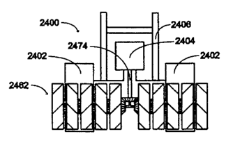
[0060] Figure 24A schematically illustrates a rotor tiller that includes a
rotary mechanism from a front
elevational view according to one embodiment of the invention. Figure 24B
schematically illustrates the
rotor tiller from Figure 24A from a side elevational view.
[0061] Figure 25A schematically illustrates a vehicle that includes rotary
mechanisms from a side
elevational view according to one embodiment of the invention. Figure 25B
schematically illustrates a
vehicle that includes rotary mechanisms from a side elevational view according
to one embodiment of the
invention.
[0062] Figure 26A schematically shows a rotary mechanism of a hair cutting
device from a side
elevational view according to one embodiment of the invention. Figure 26B
schematically shows a
removable structure of a hair cutting device from a side elevational view
according to one embodiment of
the invention. Figure 26C schematically shows the rotary mechanism of Figure
26A positioned in a
housing of a hair cutting device from a partial cross-sectional view according
to one embodiment of the
invention. Figure 26D schematically shows the rotary mechanism of Figure 26A
positioned in a housing
CA 02737322 2011-04-14
of a hair cutting device prior to placing a removable structure in an opening
of the housing from side
elevational views according to one embodiment of the invention. Figure 26E
schematically shows the
hair cutting device from Figure 26D with the removable structure positioned in
the opening of the
housing from a side elevational view according to one embodiment of the
invention. Figure 26F
schematically illustrates a person shaving facial hair using the hair cutting
device from Figure 26E from a
side elevational view according to one embodiment of the invention. Figure 26G
schematically illustrates
a cross-section of the hair cutting device from Figure 26E.
[0063] Figure 27A schematically illustrates a partially exploded view of a
tooth brushing device
according to one embodiment of the invention. Figure 27B schematically shows
an assembled tooth
brushing device from Figure 27A from a side view. Figure 27C schematically
depicts the tooth brushing
device of Figure 27B from a top side view. Figure 27D schematically depicts a
rotary mechanism from
the tooth brushing device of Figure 27B from a side view.
[0064] Figure 28A schematically shows a rotary mechanism for a tooth brushing
device from a side view
according to one embodiment of the invention. Figure 28B schematically depicts
a toothbrush head
component that includes the rotary mechanism of Figure 28A from a side view
according to one
embodiment of the invention.
[0065] Figure 29 schematically illustrates a cleaning device from a side view
according to one
embodiment of the invention.
[0066] Figure 30A schematically illustrates an exploded view of a propulsion
device according to one
embodiment of the invention. Figure 30B schematically shows the propulsion
device of Figure 30A from
a partially exploded view. Figure 30C schematically shows the propulsion
device of Figure 30A from a
partially exploded view. Figure 30D schematically illustrates the propulsion
device of Figure 30A from a
side view. Figure 30E schematically shows the propulsion device of Figure 30A
from a front side view.
Figure 30F schematically shows the propulsion device of Figure 30A from a rear
side view.
[0067] Figure 31A schematically illustrates the propulsion device of Figure
30A disposed within a
housing from a front side view according to one embodiment of the invention.
Figure 31B schematically
illustrates the propulsion device of Figure 30A disposed within a housing from
a rear side view according
to one embodiment of the invention. Figure 31C schematically illustrates the
propulsion device of Figure
30A disposed within a housing from a side view according to one embodiment of
the invention. Figure
31D schematically illustrates the propulsion device of Figure 30A disposed
within a housing from a
partially sectional front side view according to one embodiment of the
invention. Figure 31 E
21
CA 02737322 2011-04-14
schematically illustrates the propulsion device of Figure 30A disposed within
a housing from a partially
sectional side view according to one embodiment of the invention.
[0068] Figure 32A schematically shows a propulsion device including rotary
mechanisms from a
partially exploded view according to one embodiment of the invention. Figure
32B schematically
illustrates the propulsion device of Figure 32A from a side view. Figure 32C
schematically shows the
propulsion device of Figure 32A from a front side view. Figure 32D
schematically shows the propulsion
device of Figure 32A from a rear side view.
[0069] Figure 33A schematically shows a boat that includes propulsion devices
from a side view
according to one embodiment of the invention. Figure 33B schematically
illustrates the boat of Figure
33A from a front side view.
[0070] Figure 34A schematically shows an aircraft that includes propulsion
devices from a front side
view according to one embodiment of the invention. Figure 34B schematically
illustrates the aircraft of
Figure 34A from a side view.
[0071] Figure 35A schematically shows a cleaning device that includes a rotary
mechanism from a
sectional view according to one embodiment of the invention. Figure 35B
schematically shows the
cleaning device of Figure 35A from a side view.
[0072] Figure 36A schematically depicts a rotary mechanism from a top view
according to one
embodiment of the invention. Figure 36B schematically illustrates the rotary
mechanism of Figure 36A
from a side view. Figure 36C schematically illustrates the rotary mechanism of
Figure 36A from a front
side view. Figure 36D schematically illustrates the rotary mechanism of Figure
36A from a rear side
view. Figure 36E schematically shows a head component of a cleaning device
that includes the rotary
mechanism of Figure 36A from an exploded side view. Figure 36F schematically
shows the head
component of Figure 36A from a sectional view. Figure 36G schematically shows
a cleaning device that
includes the head component of Figure 36A from a side view according to one
embodiment of the
invention.
[0073] Figure 37 schematically shows a rotary mechanism from a top side view
according to one
embodiment of the invention.
[0074] Figure 38 schematically shows a cleaning device that includes a rotary
mechanism from a side
view according to one embodiment of the invention.
22
CA 02737322 2011-04-14
[0075] Figure 39 schematically shows a cleaning device that includes the
rotary mechanism of Figure
37A from a side view according to one embodiment of the invention.
[0076] Figure 40A schematically shows a cleaning device that includes the
rotary mechanism of Figure
37A and removable fluid containers prior to assembly from a side view
according to one embodiment of
the invention. Figure 40B schematically shows the cleaning device of Figure
40A following assembly
from a side view.
[0077] Figures 41 A-Q schematically show a cleaning device or implement, a
cleaning material
component, or components thereof from various views according to one exemplary
embodiment of the
invention. Figure 41A schematically illustrates a head component of a cleaning
device that includes the
rotary mechanism of Figure 21E from a side view according to one embodiment of
the invention. Figure
41B schematically shows the head component of the cleaning device of Figure
41A including a cleaning
material cartridge from a side view. Figure 41C schematically depicts the
cleaning device of Figure 41A
with an exemplary retaining component in a closed position from a side view.
Figure 41D schematically
depicts the cleaning device of Figure 41A with components of an exemplary
fluid handling mechanism
from a side view. Figure 41E schematically shows a cleaning material cartridge
being inserted into the
cleaning material support component of the cleaning device of Figure 41A from
a side view. Figure 41F
schematically shows a cleaning material cartridge operably engaging a
conveyance mechanism of the
cleaning device of Figure 41 A from a top side view. Figure 41 G schematically
depicts the head
component of the cleaning device of Figure 41A from a sectional top side view.
Figure 41H
schematically depicts a cleaning material cartridge of the cleaning device of
Figure 41A from a side view.
Figure 501 schematically depicts a cleaning material cartridge of the cleaning
device of Figure 41A from a
side view. Figure 41J schematically depicts a cleaning material cartridge of
the cleaning device of Figure
41A from a top side view. Figure 41K schematically shows a cleaning material
cartridge of the cleaning
device of Figure 41A from a bottom side view. Figure 41L schematically depicts
a cleaning material
cartridge of the cleaning device of Figure 41A from a side view. Figure 41M
schematically shows a
sectional view of a cleaning material support component of a cleaning material
cartridge according to one
embodiment of the invention. Figure 41N schematically shows the head component
of a cleaning device
of Figure 41A with a handle and a removable fluid container being positioned
relative to the cleaning
device from a side view. Figure 41 0 schematically shows the head component of
a cleaning device of
Figure 41A with a handle from a side view. Figure 41P schematically shows the
cleaning device of
Figure 410 with a handle from a front side view. Figure 41Q schematically
depicts the head component
of the cleaning device of Figure 41 A including an elevational element from a
side view.
23
CA 02737322 2011-04-14
DETAILED DESCRIPTION
1. INTRODUCTION
[0078] Before describing the invention in detail, it is to be understood that
this invention is not limited to
particular methods, rotary units, rotary mechanisms, devices, or systems,
which can vary. As used in this
specification and the appended claims, the singular forms "a," "an," and "the"
also include plural
referents unless the context clearly provides otherwise. It is also to be
understood that the terminology
used herein is for the purpose of describing particular embodiments only, and
is not intended to be
limiting. Further, unless defined otherwise, all technical and scientific
terms used herein have the same
meaning as commonly understood by one of ordinary skill in the art to which
this invention pertains. In
describing and claiming the invention, the following terminology, and
grammatical variants thereof, will
be used in accordance with the definitions set forth below.
[0079] The term "coaxially positioned" refers to objects that are positioned
relative to one another such
that they can rotate about a substantially coincident axis.
[0080] The term "fixed position" refers to objects that are positioned
relative to one another such that
they do not move separately from one another. In some embodiments, for
example, gear components
(e.g., sun gear components) are attached (e.g., integrally fabricated, bonded,
welded, adhered, or the like)
to rotational components, such that when the rotational components move in one
direction, the gear
components move in the same direction as the rotational components.
[0081] The term "counter-rotate" or "contra-rotate" refers to objects that
rotate in opposite directions
relative to one another. In some embodiments, for example, rotary mechanisms
include rotational
components that are configured to rotate in opposite directions.
[0082] The term "communicate" refers to the direct or indirect transfer or
transmission, and/or capability
of directly or indirectly transferring or transmitting, something at least
from one thing to another thing. In
some embodiments, for example, devices include housings having openings
through which hair, finger
nails, or the like can be transferred to contact implements within housing
cavities of the devices.
[0083] The invention relates to rotary units and rotary mechanisms that are
suitable for use in numerous
applications. Rotary units typically include rotational components that are
configured to rotate. In some
embodiments, for example, multiple rotary units are assembled in rotary
mechanisms such that
neighboring pairs of rotational components counter-rotate or contra-rotate
relative to one another during
operation of the rotary mechanisms. Rotational components generally include
one or more implements
that are structured to perform or effect one or more types of work as the
rotational components rotate
24
CA 02737322 2011-04-14
relative to one another in a given rotary mechanism. In certain embodiments,
implements are configured
to rotate and/or to effect the movement of other components as rotational
components rotate. The
representative embodiments described herein are intended to illustrate, but
not to limit, the invention.
Essentially any combination of components or portions thereof described herein
are optionally utilized or
adapted for use together in certain embodiments.
H. EXEMPLARY ROTARY UNITS
[00841 Figures 1 A-H schematically show a rotary unit or components thereof
according to one
embodiment of the invention. As shown, rotary unit 100 includes rotational
component 102, which
includes first gear component 104 disposed on a first side of rotational
component 102 (e.g., in an inner
region of the first side) and second gear component 106 disposed on a second
side of rotational
component 102 (e.g., in an outer region of the second side). As shown, the
first and second sides
substantially oppose one another. Gear components used with the rotary units,
rotary mechanisms, and
other applications of the invention typically include gear teeth. Any operable
gear tooth configuration
and/or type are optionally used in the rotary units, rotary mechanisms and
applications of the invention.
Second gear component 106 substantially defines gear structure receiving area
108, which is configured
to receive gear structure 110. Gear structure 110 includes support component
112 and third gear
components 114. Third gear components 114 are configured to operably engage
second gear component
106 such that when third gear components 114 rotate in a first direction,
second gear component 106 and
rotational component 102 also rotate the first direction. Third gear
components 114 are configured to
operably engage other gear components, such as a first gear component of
another rotary unit such that
when the other gear components rotate in a second direction, third gear
components 114, second gear
component 106, and rotational component 102 all rotate in the first direction.
Rotary unit 100 also
includes retaining mechanism 116 (shown as a wall or lip in this exemplary
embodiment) that is
structured to retain gear structure 110 at least partially in gear structure
receiving area 108. As further
shown in Figure 11, for example, in some embodiments during rotary unit
assembly retaining mechanism
116 is attached to rotational component 102, once gear structure 110 is
positioned in gear structure
receiving area 108, via attachment components 118 (e.g., which clip into
corresponding notches (not
within view) in rotational component 102 in this representative embodiment).
[0085] Rotary unit 100 also includes implements 120 shown as beads that can be
used, for example, as
part of a massaging device or the like. Essentially any implement (e.g.,
type(s) and/or number on a given
rotational component, etc.) is optionally adapted for use with the rotary
units of the present invention,
e.g., depending on the intended application of a given rotary unit.
Representative implements that are
optionally used include one or more of, e.g., a blade, a razor, a prong, a
peg, a claw, a tine, a chain, a
CA 02737322 2011-04-14
stake, a column, a pillar, an arch, a bracket, a gear component, a bristle, a
plume, an abrasive component,
an elastomeric component, a nail filing component, a nail buffing component, a
hair cutting component, a
massaging component, a post, or the like. Some exemplary implements 200-210
are also illustrated from
side elevational views in, e.g., Figures 2 A-F.
[0086] In addition, rotary unit 100 also includes drive mechanism component
receiving area 122 (shown
as a hole disposed through rotational component 102) that is configured to
receive a drive mechanism
component, such as a drive shaft or a portion thereof. Other exemplary drive
mechanism components are
described herein or otherwise known in the art.
[0087] Figures 3 A-G schematically illustrate a rotary unit or components
thereof according to one
embodiment of the invention. As shown, rotary unit 300 includes rotational
component 302, which
includes first gear component 304 extending from a first side, and second gear
component 306 on a
second side and substantially defining gear structure receiving area 308.
Rotary unit 300 also includes
gear structure 310, which includes third gear components 312 rotatably coupled
to support component
314. As also shown, gear structure 310 includes hole 316 that is structured to
align with drive mechanism
component receiving area 318 of rotational component 302, e.g., to receive a
drive mechanism
component, such as a drive shaft about which gear structure 310 and rotational
component 302 rotate.
[0088] Rotary unit 300 also includes a retaining mechanism that is configured
to retain gear structure
310 in position relative to rotational component 302 such that the components
can operably engage one
another during operation. The retaining mechanism of rotary unit 300 includes
groove or track 320
disposed approximately around gear structure receiving area 308 in rotational
component 302. In
addition, the retaining mechanism also includes projections 322 of gear
structure 310 that insert into
groove or track 320 such that gear structure 310 is retained and rotates
within gear structure receiving
area 308.
[0089] In some embodiments, the rotational components of the rotary units of
the invention include
implements that are configured to effect the movement of one or more other
components (e.g., propeller
components or the like) when the rotational components rotate and the
implements operably engage the
other components. To illustrate, rotational component 302 of rotary unit 300
also includes gear
component 324 that is configured to operably engage other gear components of
other components, e.g., to
effect rotation of those components when rotational component 302 rotates.
[0090] Figures 4 A-G schematically show another exemplary embodiment of a
rotary unit of the
invention. As shown, rotary unit 400 includes rotational component 402 that
includes first and second
26
CA 02737322 2011-04-14
surfaces that substantially oppose one another. First gear component 404 is
disposed on the first surface
of rotational component 402 and is configured to operably engage third gear
components of another
rotary unit. Second gear component 406 is disposed on the second surface of
rotational component 402
and substantially defines gear structure receiving area or cavity 408.
[0091] Rotary unit 400 also include gear structure 410, which includes support
structure 412 and third
gear components 414 rotatably coupled to support structure 412. Rotary unit
400 also includes a retaining
mechanism formed, in part, by groove or track 416 formed in rotational
component 402. Circular
projection 418 disposed on support structure 412 of gear structure 410 is
configured to fit within groove
or track 416 such that gear structure 410 is retained, yet permitted to
rotate, within gear structure
receiving area 408. As also shown, rotary unit 400 also includes implements
420 (shown as blades)
extending from a surface of rotational component 402.
[0092] Figures 5 A and B schematically illustrate a rotary unit according to
another exemplary
embodiment of the invention. As shown, rotary unit 500 includes rotational
component 502. First gear
component 504 extends from a first side of rotational component 502, while
gear structure 506 engages a
second gear component in a gear structure receiving area on a second side of
rotational component 502
and partially extends from the gear structure receiving area. Gear structure
includes third gear
components 508 rotatably coupled to support structure 510. Rotary unit 500
also includes a retaining
mechanism formed, in part, by groove or track 512 formed in the gear structure
receiving area of
rotational component 502. Circular projection 514 disposed on support
structure 510 of gear structure
506 is configured to fit within groove or track 512 such that gear structure
506 is retained, yet permitted
to rotate, within the gear structure receiving area of rotational component
502. First gear component 504
is configured to engage one or more third gear components of another rotary
unit. Third gear components
508 are configured to engage the second gear component in the gear structure
receiving area and a first
gear component of another rotary unit.
[0093] Figures 6 A-G schematically show a rotary unit or components thereof
according to another
representative embodiment of the invention. As shown, rotary unit 600 includes
rotational component
602. Rotational component 602 includes first gear component 604 on a first
side and second gear
component 606 on a second side. Second gear component 606 substantially
defines a gear structure
receiving area of rotational component 602. Rotary unit 600 also includes gear
structure 608 disposed
within the gear structure receiving area. Gear structure 608 includes third
gear components 610 rotatably
coupled to support component 612. Third gear components 610 are configured to
operably engage
second gear component 606 of rotational component 602 and the first gear
component of another rotary
27
CA 02737322 2011-04-14
unit or another gear component, such as a component of a drive mechanism or
the like. Gear structure
608 also includes hole or aperture 614, which is structured to align with
drive mechanism component
receiving area 616 of rotational component 602, e.g., to receive a drive
mechanism component, such as a
drive shaft about which gear structure 608 and rotational component 602
rotate. Rotary unit 600 also
includes a retaining mechanism that is configured to retain and permit gear
structure 608 to rotate within
the gear structure receiving area of rotational component 602. In particular,
support component 612 of
gear structure 608 includes partially circular indentation 618 and rotational
component 602 comprises
projection 620 (e.g., an elevated circular track or the like). Projection 620
is configured to at least
partially fit and move within partially circular indentation 618 to retain
gear structure 608 at least partially
within the gear structure receiving area when second gear component 606 and
third gear components 610
operably engage one another. In some embodiments, gear structures comprise
projections, such as
projection 620 and rotational components comprise the substantially or
partially circular indentation (e.g.,
a circular track or groove structured to receive the projection).
[0094] Rotary unit 600 also includes implements 622 that are rotatably coupled
to rotational component
602. As shown, rotatably coupled implements 622 include gear components 624
that are configured to
operably engage a corresponding gear component on a neighboring rotary unit
when the neighboring
rotary unit is disposed suitably proximal to rotary unit 600. In these
embodiments, during operation, as
neighboring rotary units counter-rotate relative to one another, rotatably
coupled implements, such as
implements 622 (e.g., shown as bristles suitable for a toothbrush, household
cleaning device, or the like)
also rotate. To further illustrate, rotary unit 600 includes gear component
626 that is configured to
operably engage rotatably coupled implements disposed on a neighboring rotary
unit.
[0095] Figures 7 A-C schematically show a rotary unit according to one
embodiment of the invention.
As shown, rotary unit 700 includes rotational component 702, which includes
first gear component 704
on a first side. Rotary unit 700 also includes a gear structure 706 disposed
and able to rotate within a gear
structure receiving area rotational component 702. Lip or wall 708 retains
gear structure 706 in the gear
structure receiving area. Rotary unit 700 also includes alignment components
that are structured to align
rotary units relative to one another, e.g., in a given device or other
application. In particular, the first side
of rotational component 702 includes circular groove 710, while the second
side of rotational component
702 includes circular ridge 712. Circular groove 710 is configured to receive
a circular ridge (e.g.,
circular ridge 812) of another rotary unit (e.g., rotary unit 800), which
circular ridge is configured to
rotate within circular groove 710. In contrast, circular ridge 712 is
configured to fit and rotate within a
circular groove (e.g., circular groove 810) of another rotary unit (e.g.,
rotary unit 800). In some
28
CA 02737322 2011-04-14
embodiments, the first side of rotational component 702 includes circular
ridge 712, while the second side
of rotational component 702 includes circular groove 710.
[0096] Rotary unit 700 also include drive mechanism component receiving area
714 that is configured
to receive a drive mechanism component (e.g., drive mechanism component 816
(shown as a drive shaft)
of rotary unit 800). Rotational component 702 is configured to rotate about a
drive mechanism
component (e.g., drive mechanism component 816 of rotary unit 800), while
first gear component 704
operably engages a gear component (e.g., a gear component of a gear structure)
of another rotary unit
(e.g., a rotary unit, such as a rotary unit 800) and gear components of gear
structure 706 operably engage
another gear component (e.g., a first gear component) of yet another rotary
unit (e.g., another rotary unit,
such as another rotary unit 800). As also shown, a surface of rotational
component 702 also includes
multiple implements 716 (shown as razors or cutting edges) that are optionally
used in hair cutting
devices or other applications.
[0097] Figures 8 A-C schematically show a rotary unit according to one
embodiment of the invention.
As shown, rotary unit 800 includes rotational component 802, which includes
first gear component 804
on a first side. Rotary unit 800 also includes a gear structure 806 disposed
and able to rotate within a gear
structure receiving area rotational component 802. Lip or wall 808 retains
gear structure 806 in the gear
structure receiving area. Rotary unit 800 also includes alignment components
that are structured to align
rotary units relative to one another, e.g., in a given device or other
application. In particular, the first side
of rotational component 802 includes circular groove 810, while the second
side of rotational component
802 includes circular ridge 812. Circular groove 810 is configured to receive
a circular ridge (e.g.,
circular ridge 712) of another rotary unit (e.g., rotary unit 700), which
circular ridge is configured to
rotate within circular groove 810. In contrast, circular ridge 812 is
configured to fit and rotate within a
circular groove (e.g., circular groove 710) of another rotary unit (e.g.,
rotary unit 700). In some
embodiments, the first side of rotational component 802 includes circular
ridge 812, while the second side
of rotational component 802 includes circular groove 810.
[0098] Rotary unit 800 also include drive mechanism component receiving area
814 that is configured to
receive a drive mechanism component (e.g., drive mechanism component 816 of a
rotary unit 800). In
the embodiment shown, drive mechanism component receiving area 814 includes a
female threaded
region that is configured to receive a male threaded region of drive mechanism
component 816 of another
rotary unit 800. As described above, another rotary unit (such as a rotary
unit 700) is configured to fit
between two rotary units 800 and rotate around a drive mechanism component 816
of one of the rotary
29
CA 02737322 2011-04-14
units 800. As also shown, a surface of rotational component 802 also includes
multiple implements 818
(shown as razors or cutting edges) that are optionally used in hair cutting
devices or other applications.
[0099] Figures 9A-L schematically depict an exemplary rotary unit or
components thereof according to
one embodiment of the invention. As shown, rotary unit 900 includes rotational
component 902 that is
configured to rotate around rotational axis 904. Rotational component 902
includes first surface 906 and
second surface 908. First surface 906 includes gear component 910 (e.g., a sun
gear component, etc.) that
is configured to operably engage one or more gear components of at least a
second rotational component
(not shown) when rotational component 902 is disposed proximal to the second
rotational component
such that when the rotational component 902 rotates in a first direction, the
second rotational component
rotates in a second direction. In addition, second surface 908 comprises gear
component 912 (e.g., a ring
gear component, etc.) that is configured to operably engage one or more gear
components (via gear
components 914) of a third rotational (not shown) component when rotational
component 902 is disposed
proximal to the third rotational component such that when rotational component
902 rotates in the first
direction, the second rotational component rotates in the second direction.
[0100] Gear structure 915 includes support component 917 and gear components
914 (e.g., planetary
gear components or the like), which are rotatably coupled to support component
917. Support component
917 of gear structure 915 also includes friction reducing materials 919 (shown
as elevated or pointed
surface features) to reduce friction as rotational component 902 rotates
relative to support component 917.
As also shown in, for example, Figures 9J-L, surface 916 of the rotational
component 902 comprises
implement 918 (shown as a plurality of bristles), which surface 916 is
configured to rotate substantially
non-perpendicular to rotational axis 904. In this embodiment, for example,
surface 916 of rotational
component 902 is configured to rotate substantially parallel to rotational
axis 904.
[0101] Rotary unit 900 also includes friction reducing materials 920 (shown as
roller balls) disposed on
first surface 906 of rotational component 902 to reduce friction as rotational
component 902 rotates
relative to another rotational component. In the embodiments in which friction
reducing materials are
utilized, essentially any friction reducing material is optionally adapted for
use with the rotary units of the
invention. Other exemplary embodiments include, for example, coatings (e.g.,
TEFLON , etc.),
lubricants, surface features, and/or the like. Rotational mechanisms typically
include one or more rotary
units 900. Exemplary rotational mechanisms are described further herein.
[0102] As further shown in Figure 91, for example, in some embodiments during
rotary unit assembly
retaining mechanism 922 is attached to another portion of rotational component
902, once gear structure
915 is positioned in a gear structure receiving area, via attachment
components 924 (e.g., which clip into
CA 02737322 2011-04-14
corresponding notches (not within view) in the portion of the rotational
component that includes retaining
mechanism 922 in this representative embodiment).
[0103] In addition, rotary unit 900 also includes drive mechanism component
receiving area 925 (shown
as a hole disposed through rotational component 902) that is configured to
receive a drive mechanism
component, such as a drive shaft or a portion thereof. Other exemplary drive
mechanism components are
described herein or otherwise known in the art.
[0104] Figures I OA-M schematically depict an exemplary rotary unit or
components thereof according to
one embodiment of the invention. As shown, rotary unit 1000 includes
rotational component 1002 that is
configured to rotate around rotational axis 1004. Rotational component 1002
includes first surface 1006
and second surface 1008. First surface 1006 includes gear component 1010
(e.g., a sun gear component,
etc.) that is configured to operably engage one or more gear components of at
least a second rotational
component (not shown) when rotational component 1002 is disposed proximal to
the second rotational
component such that when the rotational component 1002 rotates in a first
direction, the second rotational
component rotates in a second direction. In addition, second surface 1008
comprises gear component
1012 (e.g., a ring gear component, etc.) that is configured to operably engage
one or more gear
components (via gear components 1014) of a third rotational (not shown)
component when rotational
component 1002 is disposed proximal to the third rotational component such
that when rotational
component 1002 rotates in the first direction, the third rotational component
rotates in the second
direction (e.g., in the same direction as the second rotational component).
[0105] Gear structure 1015 includes support component 1017 and gear components
1014 (e.g., planetary
gear components or the like), which are rotatably coupled to support component
1017. Support
component 1017 of gear structure 1015 also includes friction reducing
materials 1019 (shown as elevated
or pointed surface features) to reduce friction as rotational component 1002
rotates relative to support
component 1017. As also shown in, for example, Figures 10K-M, surface 1016 of
the rotational
component 1002 comprises implement 1018 (shown as a plurality of bristles),
which surface 1016 is
configured to rotate substantially non-perpendicular to rotational axis 1004.
In this embodiment, for
example, surface 1016 of rotational component 1002 is configured to rotate
substantially parallel to
rotational axis 1004.
[0106] Rotary unit 1000 also includes friction reducing materials 1020 (shown
as elevated surface
features) disposed on first surface 1006 of rotational component 1002 to
reduce friction as rotational
component 1002 rotates relative to another rotational component. In the
embodiments in which friction
reducing materials are utilized, essentially any friction reducing material is
optionally adapted for use
31
CA 02737322 2011-04-14
with the rotary units of the invention. Other exemplary embodiments include,
for example, coatings (e.g.,
TEFLON , etc.), lubricants, surface features, and/or the like. In some
embodiments of the rotary units of
the invention, friction reducing materials are not utilized. Rotational
mechanisms typically include one or
more rotary units 1000. Exemplary rotational or rotary mechanisms are
described further herein.
[0107] In addition, rotary unit 1000 also includes drive mechanism component
receiving area 1024
(shown as a hole disposed through rotational component 1002) that is
configured to receive a drive
mechanism component, such as a drive shaft or a portion thereof. Other
exemplary drive mechanism
components are described herein or otherwise known in the art.
[01081 To further illustrate, Figures 1 IA-G schematically show a rotary unit
or components thereof
according to an exemplary embodiment of the invention. As shown, rotary unit
1100 includes rotational
component 1102 that is configured to rotate around rotational axis 1104.
Rotational component 1102
includes first surface 1106 and second surface 1108. First surface 1106
includes gear component 1110
(e.g., a sun gear component, etc.) that is configured to operably engage one
or more gear components (via
gear components 1114) of at least a second rotational component (not shown)
when rotational component
1102 is disposed proximal to the second rotational component such that when
the rotational component
1102 rotates in a first direction, the second rotational component rotates in
a second direction. In
addition, second surface 1108 comprises gear component 1112 (e.g., a ring gear
component, etc.) that is
configured to operably engage one or more gear components of a third
rotational (not shown) component
when rotational component 1102 is disposed proximal to the third rotational
component such that when
rotational component 1102 rotates in the first direction, the third rotational
component rotates in the
second direction (e.g., in the same direction as the second rotational
component).
[0109] Gear structure 1115 includes support component 1117 and gear components
1114 (e.g., planetary
gear components or the like), which are rotatably coupled to support component
1117. Support
component 1117 of gear structure 1115 also includes friction reducing
materials 1119 (shown as elevated
or pointed surface features) to reduce friction as rotational component 1102
rotates relative to support
component 1117. As also shown in, for example, Figures 11E-G, surface 1116 of
the rotational
component 1102 comprises implement 1118 (shown as a plurality of bristles in
this exemplary
embodiment), which surface 1116 is configured to rotate substantially non-
perpendicular to rotational
axis 1104. In this embodiment, for example, surface 1116 of rotational
component 1102 is configured to
rotate substantially parallel to rotational axis 1104. Rotational mechanisms
typically include one or more
rotary units 1100. Exemplary rotational mechanisms are described further
herein.
32
CA 02737322 2011-04-14
[0110] In addition, rotary unit 1100 also includes drive mechanism component
receiving area 1124
(shown as a hole disposed through rotational component 1102) that is
configured to receive a drive
mechanism component, such as a drive shaft or a portion thereof. Other
exemplary drive mechanism
components are described herein or otherwise known in the art.
[0111] Figures 12A-F schematically show a rotary unit or components thereof
according to an exemplary
embodiment of the invention. As shown, rotary unit 1200 includes rotational
component 1202 that
includes gear component 1210 (e.g., a sun gear component, etc.) that is
configured to operably engage
one or more gear components of at least a second rotational component (not
shown) when rotational
component 1202 is disposed proximal to the second rotational component such
that when the rotational
component 1202 rotates in a first direction, the second rotational component
rotates in a second direction.
In addition, rotational component 1202 comprises gear component 1212 (e.g., a
ring gear component,
etc.) that is configured to operably engage one or more gear components (via
gear components 1214) of a
third rotational (not shown) component when rotational component 1202 is
disposed proximal to the third
rotational component such that when rotational component 1202 rotates in the
first direction, the third
rotational component rotates in the second direction. Rotational component
1202 is structured similar to
rotational component 1002 described herein, but further includes recessed area
1203, which is described
below.
[0112] Gear structure 1215 includes support component 1217 and gear components
1214 (e.g., planetary
gear components or the like), which are rotatably coupled to support component
1217. Support
component 1217 of gear structure 1215 also includes friction reducing
materials 1219 (shown as elevated
or pointed surface features) to reduce friction as rotational component 1202
rotates relative to support
component 1217. As also shown, gear structure 1215 also includes retaining
features 1220 that are
structured to fit and move within recessed area 1203 when gear structure 1215
is disposed in the gear
structure receiving area of rotational component 1202. Retaining features 1220
further align and retain
gear structure 1215 relative to rotational component 1202. In some
embodiments, retaining features 1220
are not included. Although not shown, rotary unit 1200 also typically includes
one or more implements.
Rotational mechanisms typically include one or more rotary units 1200.
Exemplary rotational
mechanisms are described further herein.
[0113] In addition, rotary unit 1200 also includes drive mechanism component
receiving area 1224
(shown as a hole disposed through rotational component 1202) that is
configured to receive a drive
mechanism component, such as a drive shaft or a portion thereof. Other
exemplary drive mechanism
components are described herein or otherwise known in the art.
33
CA 02737322 2011-04-14
[01141 Figures 13A-E schematically show components of rotary unit according to
one exemplary
embodiment of the invention. As shown, the rotary unit includes rotational
component 1302 and gear
component 1304 (e.g., a planetary gear component or the like). Although not
shown, rotational
component 1302 typically includes one or more implements (e.g., gear
components, bristles, prongs,
blades, etc.). Rotational component 1302 includes gear component 1310 (e.g., a
sun gear component,
etc.) that is configured to operably engage or mesh with gear component 1304.
Rotational mechanisms
that include these components are described further herein.
[0115] Figures 14A-D schematically show a rotary unit or components thereof
according to an
exemplary embodiment of the invention. As shown, rotary unit 1400 includes
rotational component 1402
that includes gear component 1410 (e.g., a sun gear component, etc.), gear
component 1412-(e.g., a ring
gear component, etc.), and gear structure receiving area 1413. Gear component
1410 substantially fixedly
extends from first surface 1406 of rotational component 1402. Gear component
1410 is configured to
operably engage or mesh with one or more other gear components of another
rotary unit when gear
component 1410 is disposed proximal to the other gear components. Gear
component 1412 substantially
fixedly extends from second surface 1408 of rotational component 1402. Gear
component 1412
communicates with gear structure receiving area 1413. Gear structure receiving
area 1413 is configured
to receive gear structure 1415.
101161 Gear structure 1415 includes support component 1417 and gear components
1414 (e.g., planetary
gear components or the like), which are rotatably coupled to support component
1417. Gear components
1414 are configured to operably engage or mesh with one or more other gear
components when gear
components 1414 are disposed proximal to the other gear components. Rotational
component 1402 is
configured to rotate relative to support component 1417, which support
component 1417 is substantially
fixedly positioned when rotational component 1402 rotates relative to support
component 1417. Gear
components 1414 are configured to rotate relative to rotational component
1402. Gear structures that
include support components 1417 are described further herein. Although not
shown, rotary unit 1400 also
typically includes one or more implements. Rotational mechanisms typically
include one or more rotary
units 1400. Exemplary rotational mechanisms are described further herein.
[0117] Figures 15A-D schematically illustrate a rotary unit according to one
embodiment of the
invention. As shown, rotary unit 1500 includes rotational component 1502 that
includes first sun gear
component 1504 and second sun gear component 1506 on first and second
surfaces, respectively, of
rotational component 1502, which substantially oppose one another. First sun
gear component 1504 is
configured to operably engage one or more gear components of at least a second
rotational component
34
CA 02737322 2011-04-14
(not shown) when rotational component 1502 is disposed proximal to the second
rotational component
such that when rotational component 1502 rotates in a first direction, the
second rotational component
rotates in a second direction. Second sun gear component 1506 is configured to
operably engage one or
more gear components of at least a third rotational component (not shown) when
rotational component
1502 is disposed proximal to the third rotational component such that when
rotational component 1502
rotates in the first direction, the third rotational component rotates in the
second direction. Exemplary
gears that are optionally adapted for use with the rotary units, rotational
mechanisms, and related
applications of the invention are also described in, e.g., Dudley, Handbook of
Practical Gear Design
(Mechanical Engineering Series), CRC Press, 1st Ed. (1994) and Litvin and
Fuentes, Gear Geometry
Applied Theory, Cambridge University Press; 2 d Ed. (2004), which are both
incorporated herein in their
entirety for all purposes.
[0118] Rotary unit 1500 also includes hole 1508 disposed through rotational
component 1502. Hole
1508 is configured to receive, e.g., a drive mechanism component (e.g., an
axle, a shaft, a gear structure
component, etc.) or a support component such that rotational component 1502
can rotate around the drive
mechanism component, the support component, or the like. Rotational component
1502 also includes
friction reducing materials 1510 (shown as elevated or pointed surface
features) to reduce friction as
rotational component 1502 rotates relative to, e.g., other rotational
component. In addition, rotational
component 1502 also include implements 1512 on a surface of rotational
component 1502 that is
configured to rotate substantially non-perpendicular to a rotational axis of
rotary unit 1500. Essentially
any implement is optionally adapted for use with rotary unit 1500, including
the exemplary implements
described herein. Rotary unit 1500 is typically included in a rotational
mechanism, a device or the like.
Exemplary rotational mechanisms that include rotary unit 1500 are described
herein. In addition,
representative devices that are optionally adapted to include rotary unit 1500
are also described herein.
[0119] Figures 16 A-Q schematically illustrate a rotary unit or components
thereof according to one -
embodiment of the invention. As shown, rotary unit 1600 includes rotational
component 1602 that
includes first ring gear component 1604 and second ring gear component 1606 on
first and second
surfaces, respectively, of rotational component 1602, which substantially
oppose one another. First ring
gear component 1604 is configured to operably engage one or more gear
components of at least a second
rotational component (not shown) when rotational component 1602 is disposed
proximal to the second
rotational component such that when rotational component 1602 rotates in a
first direction, the second
rotational component rotates in a second direction. Second ring gear component
1606 is configured to
operably engage one or more gear components of at least a third rotational
component (not shown) when
rotational component 1602 is disposed proximal to the third rotational
component such that when
CA 02737322 2011-04-14
rotational component 1602 rotates in the first direction, the third rotational
component rotates in the
second direction.
[0120] Rotary unit 1600 also includes hole 1608 disposed through rotational
component 1602. Hole
1608 is configured to receive, e.g., a drive mechanism component (e.g., an
axle, a shaft, a gear structure
component, etc.) or a support component such that rotational component 1602
can rotate around the drive
mechanism component, the support component, or the like. Exemplary drive
mechanism components and
support components are described herein. Although not shown, rotational
component 1602 optionally
also includes friction reducing materials (e.g., elevated or pointed surface
features, surface coatings, roller
balls, etc.) to reduce friction as rotational component 1602 rotates relative
to, e.g., other rotational
component. In addition, rotational component 1602 also include implements 1510
on a surface of
rotational component 1602 that is configured to rotate substantially non-
perpendicular to a rotational axis
of rotary unit 1600. Essentially any implement is optionally adapted for use
with rotary unit 1600,
including the exemplary implements described herein. Rotary unit 1600 is
typically included in a
rotational mechanism, a device or the like. Exemplary rotational mechanisms
that include rotary unit
1600 are described herein. In addition, representative devices that are
optionally adapted to include rotary
unit 1600 are also described herein.
[0121] In some embodiments, rotary unit 1600 also includes gear structure
1612, which includes support
component 1614 and first planetary gear components 1616 and second planetary
gear components 1618
rotatably coupled to support component 1614. As shown, first planetary gear
components 1616 are
configured to operably engage or mesh with first ring gear component 1604,
second planetary gear
components 1618 are configured to operably engage or mesh with second ring
gear component 1606, and
rotational component 1602 is configured to rotate relative to support
component 1614, which is
substantially fixedly positioned (e.g., in an assembled rotational mechanism,
device, etc.) when rotational
component 1602 rotates relative to support component 1614. As also shown, for
example, in Figures 16
A and B, respectively, first ring gear component 1604 at least partially
defines first gear structure
receiving area 1605 and second ring gear component 1606 at least partially
defines second gear structure
receiving area 1607. First gear structure receiving area 1605 and second gear
structure receiving area
1607 are configured to receive first portion 1622 and second portion 1624,
respectively, of support
component 1614 of gear structure 1612. First portion 1622 and second portion
1624 of support
component 1614 of gear structure 1612 are described, e.g., further below.
[0122] Figure 16G schematically shows an exploded side view of gear structure
1612 according to one
embodiment of the invention. As shown, threaded region 1620 of first portion
1622 of support
36
CA 02737322 2011-04-14
component 1614 inserts into a threaded region receiving area (not within view
in Figure 16G) of second
portion 1624 of support component 1614 during assembly of gear structure 1612.
In addition, first
planetary gear components 1616 are rotatably coupled to second portion 1624 of
support component 1614
via pronged retaining elements 1626 and second planetary gear components 1618
are rotatably coupled to
first portion 1622 of support component 1614 via pronged retaining elements
1628 during assembly of
gear structure 1612. As also shown, first portion 1622 and second portion 1624
of support component
1614 include friction reducing materials 1630 (shown as elevated or pointed
surface features), e.g., to
minimize friction when rotational component 1602 rotates relative to support
component 1614 during
operation of assembled rotary unit 1600. To further illustrate, Figure 16M
schematically shows an
exploded view of rotary unit 1600 with first portion 1622 and second portion
1624 of support component
1614 of gear structure 1612 prior to assembly with rotational component 1602.
[0123] To further illustrate, Figure 16K schematically illustrates gear
structure 1612 prior to assembly
with another gear structure 1612 from a side view according to one embodiment
of the invention. As
shown, during assembly, threaded region 1632 of one support component 1614 is
inserted into threaded
region receiving area 1634 of another support component 1614 such that the
assembled support
components 1614 are substantially fixedly positioned relative to one another,
e.g., when rotational
components 1602 of rotary units 1600 rotate relative to support components
1614. Essentially any
attachment technique is optionally utilized to attach support components 1614
of gear structures 1612 to
one another or first portion 1622 and second portion 1624 of support component
1614 to one another.
Some exemplary techniques include, for example, bonding, welding, adhering, or
the like. In some
embodiments, multiple support components 1614 are fabricated as single
integral part (e.g., as a molded
part or the like).
III. EXEMPLARY ROTARY MECHANISMS
[01241 In certain embodiments, the invention provides rotary or rotational
mechanisms that include two
or more rotational components or rotary units (e.g., 2, 3, 4, 5, 6, 7, 8, 9,
10, 11, 12, 13, 14, 15, or more
rotational components or rotary units). Rotary mechanisms also typically
include at least one counter-
rotational mechanism operably coupled to one or more of the rotational
components. The counter-
rotational mechanism is generally configured to effect substantially
simultaneous counter-rotation of the
rotational components relative to one another when movement of at least a
portion of the counter-
rotational mechanism is effected. Rotary mechanisms also typically include
drive mechanisms operably
coupled to the counter-rotational mechanism and/or rotational components.
Drive mechanisms are
typically configured to effect movement of at least the portion of the counter-
rotational mechanisms such
that the rotational components substantially simultaneously counter-rotate
relative to one another. In
37
CA 02737322 2011-04-14
some embodiments, for example, multiple rotary units are included as
components (e.g., rotational
components and counter-rotational mechanisms, etc.) of rotary mechanisms.
[0125] In some embodiments, rotary units are operably coupled to one another
via one or more shafts.
To illustrate one embodiment, Figure 17A schematically depicts rotary units
100 and drive mechanism
component 1702 (shown as a shaft) prior to assembly. As shown, gear component
1704 is fixedly
coupled to shaft 1702 and is configured to operably engage third gear
components 114 (not within view in
Figures 17 A and B) of a rotary unit 100 in assembled rotary mechanism 1700.
During assembly, shaft
1702 is inserted through drive mechanism component receiving areas 122 (shown
as holes, e.g., in Figure
1 A) of rotary units 100 to operably couple rotary units 100 to one another.
Figure 17B schematically
illustrates rotary units 100 and shaft 1702 following assembly. Suitable
shafts include a variety of cross-
sectional shapes (e.g., circular, oval, triangular, square, rectangular,
polygonal, etc.). In some
embodiments, a given shaft includes multiple cross-sectional shapes. In some
of these embodiments,
individual rotary units include drive mechanism component receiving areas
(e.g., holes, apertures, etc.)
that correspond to those different cross-sectional shapes. In some
embodiments, for example, one
member of a pair of neighboring rotary units includes a square hole that fits
on a square cross-section of a
shaft, while the other member of the pair includes a circular hole that fits
on a circular cross-section of the
shaft. In these embodiments, the rotary unit with the square hole typically
rotates in a substantially fixed
position relative to the shaft, whereas the rotary unit with the circular hole
typically rotates substantially
free or independent relative to the shaft.
[0126] To further illustrate, Figures 18 A-C schematically show rotary
mechanism 1800 assembled from
pairs of rotary units 700 and 800, which are both described further herein.
More specifically, Figure 18A
schematically shows an individual pair of rotary units 700 and 800 prior to
assembly of rotary mechanism
1800 from side views. Figure 18B schematically shows partially assembled
rotary mechanism 1800 with
the rotary units of Figure 18A from side views. Figure 18C schematically
illustrates rotary mechanism
1800 that includes multiple pairs of rotary units 700 and 800.
[0127] In some embodiments, rotary units are operably coupled to one another
via one or more shafts.
To illustrate one embodiment, Figure 19A schematically depicts rotary units
900, drive mechanism
component 1902 (shown as a shaft), and cap component 1903 prior to assembly.
As shown, gear
component 1904 is fixedly coupled to shaft 1902 and is configured to operably
engage or mesh with gear
components 914 of a rotary unit 900 in assembled rotary mechanism 1900. During
assembly, shaft 1902
is inserted through drive mechanism component receiving areas 925 (shown as a
hole, e.g., in Figure 9A)
of rotary units 900 to operably couple rotary units 900 to one another. Shaft
1902 operably connects with
38
CA 02737322 2011-04-14
cap component 1903 in assembled rotary mechanism 1900, e.g., to hold rotary
units 900 in position
relative to one another. Figure 19B schematically illustrates rotary units
900, shaft 1902, and cap
component 1903 following assembly of rotary mechanism 1900. The directional
arrows in Figure 19B
schematically depict that neighboring pairs of rotary units 900 in rotary
mechanism 1900 are configured
to counter-rotate relative to one another. Figure 19C schematically shows a
portion of a rotary
mechanism that includes rotary units 900 with implements 918.
[0128] Figures 20A-O schematically show a rotary mechanism or components
thereof according to
exemplary embodiments of the invention. As shown, rotary mechanism 2000
includes four rotary units
that each include rotational component 1302 and gear component 1304. Rotary
mechanism 2000 also
includes a drive mechanism that includes shafts 2002 and motors 2004. Motors
2004 are configured to
effect rotation of shafts 2002. As shown, the drive mechanism is configured to
effect rotation of gear
components 1304 such that rotational components 1302 of neighboring or
adjacent pairs of rotary units
rotate in opposite directions. See, e.g., the directional arrows in Figure
20H, which schematically depict
the counter-rotation of neighboring pairs of rotational components 1302. As
shown, one shaft 2002 is
operably connected to a first set of two non-neighboring gear components 1304,
while the other shaft
2002 is operably connected to a second set of two non-neighboring gear
components 1304 that is different
from the first set of two non-neighboring of gear components 1304. The two
shafts 2002 are configured
to rotate in opposite directions. See, e.g., the directional arrows associated
with shafts 2002 in Figures 20
H and I. As also shown, surfaces 1305 of rotational components 1302 are
configured to rotate
substantially non-perpendicular to a rotational axis of rotational components
1302.
[0129] Any suitable drive mechanism is optionally utilized with these rotary
mechanisms. For example,
Figure 20L schematically depicts a portion of a drive mechanism from a side
view. As shown, the drive
mechanism includes motor 2004 (depicted as a dual shaft motor) that is
configured to effect rotation of
shafts 2002 in opposite directions via meshing pairs of gear components 2006.
To further illustrate,
Figures 20M-O schematically depict portions of a drive mechanism. As shown,
motor 2004 is configured
to effect rotation of shafts 2002 in opposite directions via a gear train that
includes gear components 2008.
[0130] In addition, rotary mechanism 2000 also includes positioning component
2010 (shown as a frame
structure) that is configured to position rotary units relative to one
another. As shown, shafts 2002 are
positioned relative to positioning component 2010 via mount brackets 2012,
which permit rotation of
shafts 2002. As also shown, positioning component 2010 also includes a
plurality of friction reducing
materials 2014 (shown as roller balls) disposed on a surface of positioning
component 2010 to reduce
friction as rotational components 1302 rotates relative to positioning
component 2010. In the
39
CA 02737322 2011-04-14
embodiments in which friction reducing materials are utilized, essentially any
friction reducing material is
optionally adapted for use with the rotary mechanisms of the invention. Other
exemplary embodiments
include, for example, coatings (e.g., TEFLON , etc.), lubricants, surface
features, and/or the like. Figure
20G schematically depicts positioning component 2016 according to another
exemplary embodiment.
[0131] Figures 21A-E schematically show rotary mechanisms or components
thereof according to
exemplary embodiments of the invention. As shown, rotary mechanism 2100
includes drive mechanism
component 2102, which includes ring gear component 2104 and a gear structure.
The gear structure
includes support component 2106 and planetary gear component 2108 rotatably
coupled to support
component 2106. Planetary gear component 2108 is configured to operably engage
ring gear component
2104 of drive mechanism component 2102 and gear component 1410 of rotary unit
1400. Drive
mechanism component 2102 also includes motor 2110, which is configured to
effect rotation of ring gear
component 2104 via shaft 2112. Shaft 2112 is fixedly connected to ring gear
component 2104. When
ring gear component 2104 rotates, it effects the counter-rotation of
neighboring pairs of rotary units 1400
relative to one another. See, e.g., the directional arrows associated with
Figures 21 B and C, which
schematically depict the counter-rotation of neighboring pairs of rotary units
1400. As also shown, in
assembled rotary mechanism 2100, support component 2106 is operably connected
to support
components 1417 of rotary units 1400 such that support component 2106 and
support components 1417
are substantially fixedly positioned relative to one another when ring gear
component 2104 effects the
counter-rotation of neighboring pairs of rotary units 1400 relative to one
another. Gear structures that
include support components 1417 are described further herein. To further
illustrate, Figure 21D
schematically depicts rotary mechanism 2114, which includes rotary units 1400
with implements 1418.
In addition, Figure 21E schematically illustrates rotary mechanism 2116, which
includes rotary units 1400
with implements 1418 and dual shaft motor 2118.
[01321 The gear structures of the invention include various embodiments. To
illustrate, Figure 22A
schematically illustrates gear structure 1415 prior to assembly with another
gear structure 1415 from a
side view according to one embodiment of the invention. As shown, gear
structure 1415 includes support
component 1417 and gear components 1414 (e.g., planetary gear components or
the like), which are
rotatably coupled to support component 1417. Gear components 1414 are
configured to operably engage
or mesh with one or more other gear components when gear components 1414 are
disposed proximal to
the other gear components. During assembly, threaded region 1429 of one
support component 1417 is
inserted into threaded region receiving area 1427 of another support component
1417 such that the
assembled support components 1417 are substantially fixedly positioned
relative to one another when
rotational components 1402 of rotary units 1400 rotate relative to support
components 1417 and to one
CA 02737322 2011-04-14
another. Essentially any attachment technique is optionally utilized to attach
support components 1417 to
one another. Some exemplary techniques include, for example, bonding, welding,
adhering, or the like.
In some embodiments, multiple support components 1417 are fabricated as single
integral part (e.g., as a
molded part or the like). Figure 22B schematically shows an assembly of four
gear structure 1415 from a
side view. Figure 22C schematically depicts the gear structure assembly of
Figure 22B from a rear side
view, while Figure 22D schematically depicts the gear structure assembly of
Figure 22B from a front side
view.
[0133] To further illustrate, Figure 22E schematically shows rotary mechanism
2200 that includes the
gear structure assembly of Figure 22B from a sectional view according to one
embodiment of the
invention. As shown, rotary mechanism 2200 includes four rotary units 1400.
Counter-rotation of
neighboring rotational components 1402 in rotary mechanism 2200 is effected by
drive mechanism
component 2202, which includes shaft component 2204 and gear component 2206.
Figure 22F
schematically shows rotary mechanism 2200 from a side view. Rotational
components 1402 of rotary
units 1400 of rotation mechanism 2200 are configured to rotate relative to
support components 1417,
which support components 1417 are substantially fixedly positioned when
rotational components 1402
rotates relative to support components 1417. Gear components 1414 are
configured to rotate relative to
rotational components 1402.
[0134] Figures 23A-T schematically depict a rotational mechanism or components
thereof according to
one embodiment of the invention. To illustrate, Figures 23A and C, for
example, schematically depicts a
portion of rotational mechanism 2300 from an exploded side and exploded side
sectional views,
respectively. During assembly of rotational mechanism 2300, support component
1614 of one rotary unit
1600 is inserted through hole 1508 of rotary unit 1500 and threaded region
1632 of that support
component 1614 is received and retained in threaded region receiving area of
another rotary unit 1600.
[0135] Figures 23E-P schematically show a portion of a drive mechanism
component that is utilized to
effect counter-rotation of neighboring pairs of rotary unit 1500 and rotary
unit 1600 of rotational
mechanism 2300. As shown, the portion of the drive mechanism component
includes rotational
component 2302, which includes ring gear component 2304, hole 2306, and
implements 2308. The
portion of the drive mechanism component also includes gear structure 2310,
which includes support
structure 2312 and planetary gear components 2314 rotatably coupled to support
structure 2312. Support
structure 2312 also includes friction reducing materials 2316 (shown as
elevated or pointed surface
features) to, e.g., reduce friction between support structure 2312 and
rotational component 2302 when
rotational component 2302 rotates relative to support structure 2312. Support
structure 2312 also
41
CA 02737322 2011-04-14
includes threaded region 2318, which is received by a corresponding threaded
region receiving area of
fastener 2320 (e.g., a nut or the like) through hole 2306 to hold gear
structure 2310 in position relative
rotational component 2302, yet permit rotational component 2302 to rotate
relative to support structure
2312 and planetary gear components 2314. In addition, support structure 2312
also includes threaded
region receiving area 2322, which is configured to receiving thread region
1632 of a rotary unit 1600,
e.g., in assembled rotational mechanism 2300.
[0136] As also shown, a shaft 2324 is also fixedly connected to rotational
component 2302. Although
not shown, a motor or the like is typically operably connected to shaft 2324,
which effects the rotation of
shaft 2324 and the counter-rotation of neighboring pairs of rotary unit 1500
and rotary unit 1600 of
rotational mechanism 2300 (e.g., as schematically depicted by the directional
arrows shown, e.g., in
Figure 23S) during operation. In addition, a rotary unit 1600 also operably
connects to support
component 2326 via threaded region receiving area 1634 of support structure
1614, e.g., such that support
structures 1614 of rotary units 1600 and support structure 2312 of gear
structure 2310 are substantially
fixedly positioned when rotary units 1500, rotary units 1600, and rotational
component 2302 rotate
relative to one another in rotational mechanism 2300. Essentially any support
component is optionally
used. In some embodiments, support components are included in or as part of
devices, apparatus, or other
applications of the rotational mechanisms of the invention. Exemplary support
components and
applications are described herein.
IV. EXEMPARY APPLICATIONS
[0137] Figures 24 A and B schematically illustrate a rotor tiller or
rototiller that includes a rotary
mechanism according to one embodiment of the invention. As shown, rotor tiller
2400 includes rotary
mechanism 2462 that is operably connected to motor 2404 via shaft 2474. As
also shown, rotor tiller
2400 also includes wheels 2402 and handle 2406 coupled to a support structure.
[0138] To further illustrate exemplary embodiments of the invention, Figure
25A schematically shows
vehicle 2500 from a side elevational view. As shown, vehicle 2500 includes two
rotary mechanisms 2502
and grading blade 2503, which can each be independently raised and lowered.
Rotary mechanisms can
include various embodiments, including various types of implements (e.g., as
described herein or the
like). As also shown, vehicle 2500 also includes wheels 2504, driver's
compartment 2506, and engine
compartment 2508. Vehicle 2500 can be adapted for a wide variety of uses in,
e.g., agricultural,
construction, military, or other applications. In some embodiments, for
example, vehicle 2500 is used to
till, grade, and/or otherwise move soil. As another exemplary illustration,
Figure 25B schematically
shows vehicle 2501 from a side elevational view. As shown, vehicle 2501
includes rotary mechanism
42
CA 02737322 2011-04-14
2510, which can be raised and lowered. As also shown, vehicle 2501 also
includes wheels 2504, driver's
compartment 2506, and engine compartment 2508. Vehicle 2501 can be adapted for
a wide variety of
uses. In some embodiments, for example, vehicle 2501 is used to till, grade,
and/or otherwise move soil.
[0139] In other representative embodiments, the invention provides hair
cutting devices, e.g., for cutting
facial hair, leg hair, or hair on other body parts. To illustrate, Figures 26
A-G illustrate various aspects of
a hair cutting device according to one embodiment of the invention. As shown,
hair cutting device 2600
includes housing 2602, which comprises surfaces that define cavity 2604
disposed at least partially within
housing 2602. Housing 2602 also includes opening 2606 that communicates with
cavity 2604. Rotary
mechanism 2608 (e.g., similar to the rotary mechanism described with respect
to Figure 18C) is at least
partially disposed within cavity 2604. Rotary mechanism 2608 includes multiple
rotational components
2610 and 2612 (such as the rotational components described with respect to
Figures 7 A-C and 8 A-C,
etc.) that are configured to substantially coaxially rotate (e.g., coaxially
counter-rotate) relative to one
another. Rotational components 2610 and 2612 also include cutting implements
2614 (e.g., razor blades
or other sharp edges) that are configured to cut hair via opening 2606 when
the multiple rotational
components 2610 and 2612 substantially coaxially rotate relative to one
another and cutting implements
2614 (see, e.g., implements 716 and 818 or the like) contact the hair (see,
e.g., Figure 26F). Rotary
mechanism 2608 also includes at least one counter-rotational mechanism, as
described herein (see, e.g.,
the multiple assembled rotational mechanisms schematically depicted in, e.g.,
Figures 18A-C or the like),
operably coupled to the multiple rotational components 2610 and 2612. The
counter-rotational
mechanism is configured to effect substantially simultaneous counter-rotation
of the multiple rotational
components 2610 and 2612 relative to one another when movement of at least a
portion of the counter-
rotational mechanism is effected. That is, rotational component 2610 is
configured to rotate in a direction
that is opposite the direction of rotation of rotational component 2612. In
some embodiments, the
rotational components are configured to coaxially counter-oscillate relative
to one another about an axis
of rotation of the rotary mechanism. In some of these embodiments, cutting
implements include dual-side
cutting edges, e.g., to cutting hair in both directions of the oscillation.
[0140] As also shown, hair cutting device 2600 also includes a drive mechanism
operably coupled to the
counter-rotational mechanism and rotational components. In the embodiment
shown, for example, in
Figures 26A and 26C, the drive mechanism includes motor 2616 (e.g., a stepper
motor, a servo motor,
etc.), which is configured to effect movement of the counter-rotational
mechanism via shaft 2618 such
that the multiple rotational components 2610 and 2612 substantially
simultaneously counter-rotate
relative to one another. As also shown, switch 2617 (e.g., on/off switch, a
variable speed control switch,
and/or the like) is operably connected to motor 2616. Although not shown, hair
cutting device 2608 also
43
CA 02737322 2011-04-14
typically includes a power source (e.g., a power cord that plugs into a wall
socket, a battery (rechargeable
or not), a photovoltaic cell, etc.) operably connected to motor 2616.
[0141] Hair cutting device 2600 also includes removable structure 2620 (e.g.,
a shaving foil structure or
the like) disposed in opening 2606. Removable structure 2620 comprises holes
2622 via which hair is cut
when the multiple rotational components 2610 and 2612 substantially coaxially
counter-rotate relative to
one another and cutting implements 2614 contact the hair. Hair cutting devices
also typically include
support structures that are structured to support at least a portion of the
rotational components, the
counter-rotational mechanism, and/or the drive mechanism within the device
housings. As shown in
Figure 26F, for example, hair cutting device 2600 is dimensioned to be hand-
held (i.e., person 2621 is
holding hair cutting device 2600 in his hand). As shown, e.g., Figure 26G
housing 2602 of hair cutting
device 2600 comprises at least one substantially circular cross-section.
[0142] Figures 27 A-D schematically illustrate an exemplary tooth brushing
device or components
thereof according to one embodiment of the invention. As shown, tooth brushing
device 2700 includes
rotary mechanism 2702, which includes a plurality of rotary units 600, as
described above. Tooth
brushing device 2700 also includes toothbrush head component 2704 and handle
component 2706.
Toothbrush head component 2704 includes rotary mechanism housing 2708, which
partially exposes a
portion of the bristles of rotary mechanism 2702 through an opening in rotary
mechanism housing 2708
during operation. Toothbrush head gear components 2710 and drive shaft 2712
also extend from a
portion of rotary mechanism housing 2708. Drive shaft 2712 is received through
drive mechanism
receiving areas of rotational components 602 of rotary units 600 of rotary
mechanism 2702. Toothbrush
head gear components 2710 operably engage gear components 604 and 624 of a
rotary unit 600 to effect
counter rotation of neighboring rotational components 602 and implements 622
of rotary mechanism
2702. Rotary mechanism cap 2714 attaches to drive shaft 2712 to retain rotary
mechanism positioned
relative to toothbrush head gear components 2710. Handle component 2706 houses
a motor (not within
view) the operably connects to toothbrush head gear components 2710 and drive
shaft 2712. A power
source, such as a rechargeable battery or the like is also housed in handle
component 2706 is some
embodiments. In certain embodiments, the motor is optionally connected to
other types of power sources,
such as photovoltaic cells attached to handle component 2706, external power
sources, or the like. As
also shown, handle component 2706 also include switch 2716, which is used,
e.g., to turn tooth brushing
device 2700 on and off, regulate speeds or modes of rotary unit rotation, or
the like.
[0143] Figures 28 A and B schematically show an exemplary rotary mechanism or
toothbrush head
component that is optionally used, e.g., with handle component 2706 of tooth
brushing device 2700. As
44
CA 02737322 2011-04-14
shown, rotary mechanism 2800 includes a plurality of rotary units 600 in which
implements 2802 (raised
elastomeric regions, e.g., for tooth polishing) have been substituted for
implements 622 on several
individual rotary units. Figure 28B schematically shows toothbrush head
component 2804, which
includes rotary mechanism 2800.
[0144] Figure 29 schematically illustrates an exemplary cleaning device from a
side view according to
one embodiment of the invention. As shown, cleaning device 2900 includes a
rotary mechanism that
includes rotary units similar to rotary units 800, which are described further
herein. Exemplary uses of
cleaning device 3900 include cleaning outdoor cooking grills, dishes, and
toilets, among many possible
applications.
[0145] To further illustrate representative embodiments, rotary units and
rotary mechanisms are
optionally used or adapted for use in various types of engines and other
propulsion devices or systems.
For example, Figures 30 A-F schematically illustrate a propulsion device or
components thereof
according to one embodiment of the invention. As shown, propulsion device 3000
includes two rotary
mechanisms 3002 and propeller component 3004. Rotary mechanisms 3002 include a
plurality of rotary
units 300, as described herein. Rotary units 300 are operably coupled to one
another via shaft 3006,
which includes gear component 3008. Shaft 3006 operably connects to motor 3010
and rotary
mechanism cap 3012. Gear component 3008 operably engages third gear components
312 of gear
structure 310 of a rotary unit 300 such that when motor 3010 effects the
rotation of gear component 3008,
gear component 3008 effects the counter rotation of neighboring pairs of
rotary units 300. Gear
components 324 of rotary units 300 operably engage corresponding gear
components of propeller units
3014 (e.g., rotational units or the like) to effect the counter rotation of
neighboring pairs of propeller units
3014 of propeller component 3004, and thereby propulsion. Rotary mechanism cap
3012 aligns and
maintains the position of rotary units 300 relative to one another. Although
two rotary mechanisms 3002
are depicted in this propulsion device embodiment, fewer or more that two
rotary mechanisms are
optionally used.
[0146] Figures 32 A-D schematically illustrate a propulsion device or
components thereof according to
one embodiment of the invention. As shown, propulsion device 3200 includes two
rotary mechanisms
3202 and propeller component 3004. Rotary mechanisms 3202 include a plurality
of rotational
components 3204. Rotational components 3204 are fixedly coupled to one another
via shaft 3206. Shaft
3206 operably connects to motor 3010 and rotary mechanism cap 3012. As shown,
one shaft 3206 is
fixedly coupled to a first set of four non-neighboring gear components 3204,
while the other shaft 3206 is
fixedly coupled to a second set of four non-neighboring gear components 3204
that is different from the
CA 02737322 2011-04-14
first set of four non-neighboring of gear components 3204. The two shafts 3206
are configured to rotate
in opposite directions. See, e.g., the directional arrows associated with the
two rotary mechanisms 3202
in Figure 32B. As shown, in an assembled propulsion device 3200, gear
components 3204 of the first and
second sets of four non-neighboring of gear components 3204 mesh with
corresponding gear components
of different propeller units 3014 (e.g., rotational units or the like) of
propeller component 3004 such that
when the first and second sets of four non-neighboring of gear components 3204
rotate in opposite
directions to one another, neighboring pairs of propeller units 3014 of
propeller component 3004 counter-
rotate relative to one another, and thereby effect propulsion.
[0147] Propeller component 3004 of propulsion device 3000 and 3200 includes a
plurality of propeller
units 3014 (e.g., rotational units or the like), which in this embodiment each
include a plurality of
propellers 3016. Many different types of propellers are optionally used or
adapted for use in the engines
or propulsion devices of the invention. In some embodiments, for example,
individual propeller
components 3004 may have propellers 3016 that differ in size from the
propellers of other propeller
components in a given propulsion device 3000 or propulsion device 3200.
Propeller units 3014 are
operably coupled together in propeller component 3004 via propeller component
shaft 3018 and propeller
component cap 3020. As also shown, certain propeller units 3014 include
rotational alignment
components 3022, which are positioned and rotate in corresponding rotational
positioning components
3107 of propulsion component housing 3100 (e.g., a positioning component or
the like), e.g., to prevent
propeller units 3014 from contacting propulsion component housing 3100 during
operation. See, e.g.,
Figures 31 D and E.
[0148] The engine and propulsion devices have many different uses. For
example, they are optionally
used or adapted for use with watercraft (e.g.., boats, submarines, surfboards,
personal watercraft, diving
or scuba propulsion aides, and the like) or aircraft. To illustrate, Figures
33 A and B schematically depict
boat 3300, which includes several housed propulsion devices 3302. To further
illustrate, Figures 34 A
and B schematically depict aircraft 3400, which includes housed propulsion
devices 3402.
[0149] Figure 35A schematically shows cleaning device 3500 that includes a
rotary mechanism from a
sectional view according to one embodiment of the invention. Figure 35B
schematically shows cleaning
device 3500 from a side view. As shown, the rotary mechanism of cleaning
device 3500 includes rotary
units 900, which each include implements 918. Rotary units 900 are aligned
relative to one another and
rotate around shaft 3502. The rotary mechanism is positioned relative to
housing 3504 via mounting
components 3506. As also shown, cleaning device 3500 also includes motor 3508,
which effects the
counter-rotation of rotary units 900 in the rotary mechanism via drive shaft
3510 and meshed gear
46
CA 02737322 2011-04-14
components 3512 and 3514. Cleaning device 3500 also includes power source 3516
(e.g., a battery or the
like), which is operably connected to motor 3508 and switch 3518 in a handle
portion of housing 3504.
Cleaning device 3500 is optionally adapted for a variety of uses including,
for example, cleaning dishes,
cleaning countertops, cleaning floors, cleaning barbeque grills, cleaning
ovens, cleaning toilets, buffing
automobiles or other vehicles, and the like.
[0150] Figures 36A-G schematically depict a cleaning device or components
thereof. As shown,
cleaning device 3600 includes rotary mechanism 3602. Rotary mechanism 3602
includes rotary units
900, which each include implements 918. Rotary units 900 are aligned relative
to one another and rotate
around shafts 3604. Rotary mechanism 3602 is positioned relative to housing
3606 of head component
3607 via mounting components 3608. As also shown, cleaning device 3600 also
includes motor 3610,
which effects the counter-rotation of rotary units 900 in rotary mechanism
3602 via drive shaft 3612 and
meshed gear components 3614 and 3616. Although not within view, cleaning
device 3600 also includes a
power source (e.g., a battery or the like) or is connectable with a power
source (e.g., via a power cord or
the like), which operably connects to motor 3610 and switch 3618. As shown,
switch 3618 is disposed
on handle component 3620, which operably connects to head component 3607.
[0151] Figure 37 schematically shows rotary mechanism 3700 from a top side
view according to one
embodiment of the invention. Rotary mechanism 3700 is optionally adapted for
use in the cleaning
devices and other applications of the invention. Rotary mechanism 3700
includes rotary units 900, which
each include implements 918. Rotary units 900 are aligned relative to one
another and rotate around
shafts 3702. As also shown, rotary mechanism 3700 also includes motor 3704,
which effects the counter-
rotation of rotary units 900 in rotary mechanism 3700 via drive shaft 3706 and
meshed gear components
3708.
[0152] Figure 38 schematically shows cleaning device 3800 that includes rotary
mechanism 3602 from a
side view according to one embodiment of the invention. As shown, cleaning
device 3800 includes head
component 3607 (as described above), which is operably connected to handle
component 3802. As also
shown, handle component 3802 includes switch 3804, which is operably connected
to motor 3610 (not
within view). Switch 3804 is typically used to turn cleaning device 3800 on
and off, varying a rate or
mode of rotary unit rotation, and the like.
[0153] Figure 39 schematically shows cleaning device 3900 that includes rotary
mechanism 5502 from a
side view according to one embodiment of the invention. As shown, cleaning
device 3900 includes head
component 3607 (as described above), which is operably connected to handle
component 3902. As also
shown, handle component 3902 includes switch 3904, which is operably connected
to motor 3610 (not
47
CA 02737322 2011-04-14
within view). Cleaning device 3900 also includes suction component 3906, which
communicates with an
internal cavity of head component 3607 that includes rotary mechanism 3602 and
with waste container
3908. Suction component 3906 includes a suction source (e.g., a vacuum source)
and a conduit. The
suction source is configured to generate suction force sufficient to convey
waste from head component
3607 through the conduit to waste container 3908. Switch 3904 is also operably
connected to suction
component 3906. Switch 3904 is typically used to turn cleaning device 3900 on
and off (rotary unit
rotation and/or suction), varying a rate or mode of rotary unit rotation
and/or suction component suction,
and the like.
[0154] Figure 40A schematically shows cleaning device 4000 that includes
rotary mechanism 3602 and
removable fluid containers 4002 (e.g., a fluid source or the like) and 4004
(e.g., a fluid waste container or
the like) prior to assembly from a side view according to one embodiment of
the invention. Figure 40B
schematically shows cleaning device 4000 with fluid containers 4002 and 4004
positioned relative to
handle 4006 on support components 4003 and 4005, respectively, from a side
view. As shown, cleaning
device 4000 includes head component 3607 (as described above), which is
operably connected to handle
component 4006. As also shown, handle component 4006 includes switch 4008,
which is operably
connected to motor 3610 (not within view).
[0155] In some embodiments, cleaning devices or implements include fluid
handling mechanisms that
can be used, for example, to distribute fluid (e.g., a cleaning fluid, etc.)
to a surface to cleaned or the like.
To illustrate one exemplary embodiment, cleaning device 4000 includes a fluid
handling mechanism that
comprises a fluid source (container 4002) and fluid outlet (nozzle 4010)
(shown disposed proximal to a
surface of head component 3607). The fluid handling mechanism is configured to
convey fluid from
container 4002 to nozzle 4010, which communicate via fluid conduit 4012. The
fluid handling
mechanism of cleaning device 4000 also includes pumping mechanism 4014 (e.g.,
a rotary lobe pump, a
rotary gear pump, a screw pump, a gear pump, a peristaltic pump, or the like)
that is configured to pump
the fluid from container 4002 to nozzle 4010. As also shown, the fluid
handling mechanism also includes
vaporization component 4016 (e.g., a steam vaporizer or the like) that is
configured to vaporize the fluid
at least proximal to nozzle 4010. In the embodiment shown, container 4002 is
removable from cleaning
device 4000 such that container 4002 can be, e.g., refilled with a cleaning
fluid, replaced with a new
container when container 4002 is fabricated as a consumable component of
cleaning device 4000, etc. In
some embodiments, containers are fabricated integral or otherwise fixedly
attached to cleaning devices.
Switch 4008 is also configured to effect operation of pumping mechanism 4014
and vaporization
component 4016.
48
CA 02737322 2011-04-14
[0156] Cleaning device 4000 also includes suction component 4018 (e.g., vacuum
source or component,
pumping mechanism, and/or the like) that comprises inlet 4020 and outlet 4022.
As shown, suction
component 4018 is disposed proximal to head component 3607. Outlet 4022
communicates with
container 4004 via conduit 4024. Switch 4008 is also configured to effect
operation of suction
component 4018.
[0157] During operation, cleaning fluid is conveyed from container 4002,
vaporized, and sprayed from
nozzle 4010 to wet a surface to be cleaned. Rotary mechanism 3602 of head
component 3607 scrubs the
wetted surface and suction component 4018 conveys waste fluid from the wetted
surface through inlet
4020 to container 4004. Cleaning devices or implements, or components thereof,
that optionally are
adapted for use with the cleaning devices of the invention are also described
in, e.g., U.S. Provisional
Patent Application No. 61/317,746, entitled "CLEANING IMPLEMENTS, CLEANING
MATERIAL
COMPONENTS, AND RELATED METHODS", filed on March 26, 2010, which is
incorporated by
reference in its entirety.
[0158] To further illustrate, Figures 41 A-Q schematically show cleaning
devices, cleaning material
components, or components thereof from various views according to exemplary
embodiments of the
invention. As shown, cleaning device 4100 includes head component 4102 which
includes cleaning
material support component 4104 and cleaning surface component 4106. Cleaning
material support
component 4104 includes cleaning material support component surfaces 4108 that
at least partially define
cleaning material receiving areas 4110 (shown as cleaning implement cartridge
receiving areas). As also
shown, cleaning material support components 4104 include openings 4112 that
are structured such that
cleaning material receiving areas 4110 communicate with cleaning surface
component 4106. As shown,
cleaning material receiving areas 4110 are configured to receive cleaning
material component 4114
(shown as a cleaning implement cartridge that includes a cleaning material
roll) such that at least a
portion of cleaning material component 4114 is movable to and/or from cleaning
material receiving area
4110 to extend over at least a portion of cleaning surface component 4106. In
addition, cleaning device
4100 also includes retaining component 4120 (shown as a door structure) that
operably engages cleaning
material support component 4104 via slide component 4122 in this exemplary
embodiment. As shown,
head component 4102 also includes rotary mechanism 2116.
[0159] Cleaning material component 4114 includes cleaning material support
structures 4130 and
cleaning material 4126 (shown as a rolled sheet of cleaning material).
Cleaning material support
structures 4130 (shown as substantially cylindrically-shaped housings) form
cavities that are each
structured to house and support cleaning material 4126 such that cleaning
material 4126 is movable to
49
CA 02737322 2011-04-14
and/or from cleaning material support structures 4130 via orifices 4132.
Orifices 4132 are configured to
communicate with openings 4112. Cleaning material support structures and
corresponding cleaning
material receiving areas are optionally formed to include various cross-
sectional shapes, including, e.g.,
circles, ovals, squares, rectangles, regular n-sided polygons, irregular n-
sided polygons, etc. As shown,
cleaning material support structure 4130 is configured to be received in
cleaning material receiving area
4110 of cleaning device 4100 and cleaning material 4126 is configured to
extend over cleaning surface
component 4106 of cleaning device 4100 via orifices 4132 and openings 4112.
[01601 In some embodiments, cleaning material support structures and/or
cleaning materials of cleaning
material components include one or more alignment components that are
configured to align cleaning
materials relative to cleaning material support structures. To illustrate,
cleaning material support
structures 4130 of cleaning material component 4114 includes rod 4134 that
extends within cleaning
material support structure 4130. As shown, the alignment component (rod 4134)
of cleaning material
support structure 4130 inserts into a corresponding central receiving area of
the cleaning material roll
(cleaning material 4126) to align cleaning material 4126 relative to cleaning
material support structures
4130.
[01611 In certain embodiments, cleaning devices and/or cleaning material
components operably connect,
or are operably connectable, to conveyance mechanisms or components thereof to
effect conveyance of
cleaning materials, e.g., selected incremental distances. In cleaning device
4100, for example, rod 4134
extends through cleaning material support structure 4130 and operably connects
to conveyance
mechanism component 4140 that is configured to operably engage gear components
4139. In particular,
projections 4137 of conveyance mechanism component 4140 are configured to be
received by projection
receiving areas 4135 of gear components 4139. Gear components 4139 are
configured to operably
engage gear component 4141 of head component 4102 when cleaning material
component 4114 is
disposed in cleaning material receiving areas 4110. As shown, gear component
4141 is operably
connected to motor 4143 (e.g., a stepper motor, a servo motor, etc.) via shaft
4145. Power source 4147
(shown as a battery, e.g., a disposable battery, a rechargeable battery, etc.)
operably connects to motor
4143 to provide power to motor 4143. Essentially any power source is
optionally adapted for use with the
cleaning devices of the invention. In some embodiments, for example, motors
are operably connected to
power cords that plug into power outlets. In other exemplary embodiments,
photovoltaic cells are
mounted cleaning devices to provide power to motors. Motor 4143 effects
rotation of cleaning material
roll (cleaning material 4126) (via gear components 4139 and 4141) selected
distances such that cleaning
material 4126 is positioned at selected positions relative to cleaning surface
component 4106. Although
CA 02737322 2011-04-14
not within view, motor 2118 is also operably connected to power source 4147.
Motor 2118 effects
rotation of rotary mechanism 2116.
[01621 Typically, cleaning material support components of cleaning devices
and/or cleaning material
components include one or more alignment features that are structured to align
those components relative
to one another when the cleaning material components are disposed in the
cleaning material receiving
areas of the cleaning devices. In one exemplary embodiment, for example,
cleaning material support
structure 4130 and cleaning material support component 4104 include alignment
features 4142 and 4144,
respectively (schematically shown as corresponding tongue and groove-type
components), that are
structured to align cleaning material support structure 4130 relative to
cleaning material support
component 4104 cleaning device 4100.
[01631 The cleaning devices of the invention typically include one or more
handle components. As
shown in Figures 41N-P, for example, cleaning device 4100 includes handle 4146
operably connected to
head component 4102. Handle 4146 is pivotally connected to head component 4102
via pivot mechanism
4148 (shown as a ball and socket mechanism). As also shown, handle 4146
includes switch 4150 which
is operably connected to motor 4143. Switch 4150 is used to effect movement of
cleaning material 4126
via the conveyance mechanism described above.
[01641 In some embodiments, cleaning devices include fluid handling mechanisms
that can be used, for
example, to distribute fluid (e.g., a cleaning fluid, etc.) to a surface to
cleaned, to a cleaning material of a
cleaning device (e.g., to moisten the cleaning material prior to or during use
of the cleaning device, etc.),
and/or the like. To illustrate one exemplary embodiment, cleaning device 4100
includes a fluid handling
mechanism that comprises a fluid source (container 4154) and fluid outlets
(nozzles 4152) (shown
disposed proximal to a surface of head component 4102). The fluid handling
mechanism is configured to
convey fluid from container 4154 to nozzles 4152, which communicate via fluid
conduit 4156. The fluid
handling mechanism of cleaning device 4100 also includes pumping mechanism
4158 (e.g., a rotary lobe
pump, a rotary gear pump, a screw pump, a gear pump, a peristaltic pump, or
the like) that is configured
to pump the fluid from container 4154 to nozzles 4152. As also shown, the
fluid handling mechanism
also includes vaporization component 4160 (e.g., a steam vaporizer or the
like) that is configured to
vaporize the fluid at least proximal to nozzles 4152. In the embodiment shown,
container 4154 is
removable from cleaning device 4100 such that container 4154 can be, e.g.,
refilled with a cleaning fluid,
replaced with a new container when container 4154 is fabricated as a
consumable component of cleaning
device 4100, etc. In some embodiments, containers are fabricated integral or
otherwise fixedly attached
to cleaning devices. Switch 4150 is also configured to effect operation of
pumping mechanism 4158 and
51
CA 02737322 2011-04-14
vaporization component 4160. As shown in Figure 41Q, for example, head
component 4102 of cleaning
device 4100 includes elevational element 4162 from a side view. Elevational
elements are also described
in, e.g., U.S. Provisional Patent Application No. 61/317,746, entitled
"CLEANING IMPLEMENTS,
CLEANING MATERIAL COMPONENTS, AND RELATED METHODS", filed on March 26, 2010,
which is incorporated by reference in its entirety.
[0165] In some embodiments, the cleaning devices or components thereof of the
invention are optionally
adapted for use as part of various types of robotic cleaning implements.
Exemplary robotic cleaners or
aspect there of that are optionally adapted for use with these cleaning
implements or components are
described in, e.g., U.S. Patent Nos. US 7,571,511, entitled "Autonomous floor
cleaning robot" to Jones et
al, which issued August 11, 2009; US 7,620,476, entitled "Autonomous surface
cleaning robot for dry
cleaning" to Morse et al., which issued November 17, 2009; US 7,636,982,
entitled "Autonomous floor
cleaning robot" to Jones et al, which issued December 29, 2009; and US
7,761,954, entitled
"Autonomous surface cleaning robot for wet and dry cleaning" to Ziegler et
al., which issued July 27,
2010; and U.S. Patent Application Publication Nos. US 2009/0281661, entitled
"Application of
localization, positioning & navigation systems for robotic enabled mobile
products" by Dooley et at.,
which published November 12, 2009 and US 2009/0306822, entitled "Multi-
function robotic device" by
Augenbraun et al., which published December 10, 2009, which are each
incorporated by reference herein
in their entirety.
[0166] Device components (e.g., rotary units, rotary mechanisms, drive
mechanism components, gear
components, shafts, rotational components, device housings, doors, support
structures, etc.) are optionally
formed by various fabrication techniques or combinations of such techniques
including, e.g., cast
molding, stamping, machining, embossing, extrusion, engraving, injection
molding, etching (e.g.,
electrochemical etching, etc.), or other techniques. These and other suitable
fabrication techniques are
generally known in the art and described in, e.g., Molinari et al. (Eds.),
Metal Cutting and High Speed
Machining, Kluwer Academic Publishers (2002), Altintas, Manufacturing
Automation: Metal Cutting
Mechanics, Machine Tool Vibrations, and CNC Design, Cambridge University Press
(2000), Stephenson
et al., Metal Cutting Theory and Practice, Marcel Dekker (1997), Fundamentals
of Injection Molding, W.
J. T. Associates (2000), Whelan, Injection Molding of Thermoplastics
Materials, Vol. 2, Chapman & Hall
(1991), Rosato, Injection Molding Handbook, 3rd Ed., Kluwer Academic
Publishers (2000), Fisher,
Extrusion of Plastics, Halsted Press (1976), and Chung, Extrusion of Polymers:
Theory and Practice,
Hanser-Gardner Publications (2000), which are each incorporated by reference.
Exemplary materials
optionally used to fabricate device components include, e.g., metal, glass,
wood, polymethylmethacrylate,
polyethylene, polydimethylsiloxane, polyetheretherketone,
polytetrafluoroethylene, polystyrene,
52
CA 02737322 2011-04-14
polyvinylchloride, polypropylene, polysulfone, polymethylpentene, and
polycarbonate, among many
others. In certain embodiments, following fabrication, device components are
optionally further
processed, e.g., by painting, coating surfaces with a hydrophilic coating, a
hydrophobic coating, or the
like.
[0167] Exemplary rotary units, rotational mechanisms, related applications,
and other aspects, which are
optionally adapted, e.g., for use with the rotary units and rotational
mechanisms described herein are also
described in, e.g., U.S. Patent Application No. 12/577,326, entitled "ROTARY
UNITS, MECHANISMS,
AND RELATED DEVICES", filed on October 12, 2009, U.S. Provisional Patent
Application No.
61/104,748, entitled "ROTARY UNITS, MECHANISMS, AND RELATED DEVICES", filed on
October 12, 2008, International Application No. PCTIUS2009/060386, entitled
"ROTARY UNITS,
MECHANISMS, AND RELATED DEVICES", filed on October 12, 2009, U.S. Provisional
Patent
Application No. 61/365,290, entitled "ROTARY UNITS, MECHANISMS, AND RELATED
DEVICES",
filed on July 16, 2010, and U.S. Provisional Patent Application No.
61/317,746, entitled "CLEANING
IMPLEMENTS, CLEANING MATERIAL COMPONENTS, AND RELATED METHODS", filed on
March 26, 2010, which are each incorporated herein by reference in their
entirety for all purposes.
[0168] While the foregoing invention has been described in some detail for
purposes of clarity and
understanding, it will be clear to one skilled in the art from a reading of
this disclosure that various
changes in form and detail can be made without departing from the true scope
of the invention. For
example, all the techniques and apparatus described above can be used in
various combinations. All
publications, patents, patent applications, and/or other documents cited in
this application are
incorporated by reference in their entirety for all purposes to the same
extent as if each individual
publication, patent, patent application, and/or other document were
individually indicated to be
incorporated by reference for all purposes.
53