Note: Descriptions are shown in the official language in which they were submitted.
CA 02737539 2011-03-17
WO 2010/033715 PCT/US2009/057336
FLIP CAP
BACKGROUND
[0001] This disclosure relates to an improved cap for a fluid bottle or
container,
and more particularly a reclosable cap that facilitates dispensing of fluid
from an
opening of the container, and also includes a hinged lid that effectively
seals the
container.
[0002] Published International Application WO2008/091936 is a commonly
owned application and generally directed to a closure cap used in the same
general
environment of the present disclosure, the disclosure of which is expressly
incorporated herein by reference. Although commercially successful, there is a
need
for improved sealing capability, and a need to enhance pouring of the contents
from
the container. Generally, these types of caps are a molded structure in which
the
body includes internal thread portions that allow the cap to be threaded onto
an
externally threaded shoulder of the associated container, or alternatively to
be snap-
fit over the threaded shoulder. The shoulder surrounds the dispensing opening
of
the container. In some arrangements, the opening is flush or slightly below a
plane
generally defining a remainder of an upper surface of the container while in
other
instances, the opening protrudes above the upper surface.
[0003] As shown in the noted published international patent application, an
enlarged diamond-shaped opening is provided in the cap with a vertex of an
acute
angle serving as the pour region of the cap. The oppositely disposed vertex of
the
diamond-shaped opening is located more closely to the hinge. A lid is joined
to the
body preferably by a living hinge, i.e., a thin region of plastic material
that is
integrally formed between the lid and the cap body. In this manner, once
contents
have been dispensed from the container through the cap opening, the lid is
then
positioned over the opening and seals contents of the container from the
external
environment.
[0004] This known arrangement also preferably includes a foil/polyethylene
composite seal that is fusion bonded to an upper perimeter of the dispensing
opening. Subsequently, the cap is received over the opening. Thus, in order
for the
container contents to be dispensed, a consumer must initially remove the cap,
peel
CA 02737539 2011-03-17
WO 2010/033715 PCT/US2009/057336
2
off the foil/polyethylene seal, and then re-install the cap onto the
container. The
foil/polyethylene seal assures that the container or bottle is sealed from the
external
environment. In other words, improved sealing is desired during shipment of
the
filled container from the manufacturing plant to the store.
[0005] Accordingly, a need exists for a reclosable cap assembly that
eliminates
the use of a foil/polyethylene composite sealed beneath the cap during
shipping, that
is substantially smaller in height, and effectively seals and re-seals the
container,
and that need not be removed from the container by the consumer prior to
dispensing the contents of the container.
SUMMARY OF THE DISCLOSURE
[0006] An improved cap dimensioned for receipt on a threaded shoulder
surrounding a container opening is provided.
[0007] The cap includes an annular body having an internally threaded sidewall
where a thread member extends around at least a portion of the sidewall, a
closing
surface extending substantially perpendicular to the sidewall and dimensioned
to
cover the associated container opening, an opening in the closing surface
having
first, second, and third portions that form distinct, interconnected narrow,
intermediate, and large pour opening portions. The lid is selectively received
on a
closing surface and includes a seal extending outwardly from a surface where
the
seal has first, second, and third portions that conform to the first, second,
and third
portions of the opening.
[0008] The opening first, second, and third portions preferably each include
arcuate perimeters.
[0009] The arcuate perimeters of the openings of the first and third portions
each
extend over approximately 235 . A hinge connects the lid to the body.
[0010] The narrow pour opening portion is disposed opposite from the hinge.
Further, the first, second, and third portions of the opening are preferably
disposed
in linear relation.
CA 02737539 2011-03-17
WO 2010/033715 PCT/US2009/057336
3
[0011] The closing surface includes a first tapering region that extends from
a
maximum diameter of a large pour opening portion to and around perimeter
portions
of the narrow and intermediate pour opening portions.
[0012] The first tapering region preferably extends from opposite edges of the
maximum diameter of the large pour opening portion toward a pour lip region in
a
direction substantially perpendicular to a pivot axis of a hinge.
[0013] A second tapering region extends downwardly from an outer perimeter of
the closing surface toward a center of the closing surface.
[0014] A primary benefit of the present disclosure relates to the reduced cost
associated with eliminating a foil/polyethylene composite seal, and
substantially
reducing the size of the cap, namely reducing the height of the cap.
[0015] Yet another advantage resides in the ability to more effectively reseal
the
opening.
[0016] A further advantage is that a further tamper preventive feature is
provided
by securing the cap to the container and likewise that a consumer never has to
remove the cap from the container.
[0017] Still other benefits and advantages of this disclosure will become more
apparent from the following detailed description.
BRIEF DESCRIPTION OF THE DRAWINGS
[0018] FIGURE 1 is a plan view of a first embodiment of a new cap assembly.
[0019] FIGURE 2 is a cross sectional view taken generally along the lines 2-2
of
FIGURE 1.
[0020] FIGURE 3 is a plan view from an underside of the cap with the lid in an
open position relative to the body.
[0021] FIGURE 4 is a plan view from an upper side of the cap with the lid in
an
open position relative to the body.
[0022] FIGURE 5 is an elevational view of the associated container and
illustrating receipt of a cap thereon.
[0023] FIGURE 6 is an elevational view of the container opening with a second
embodiment of a cap shown installed thereon in an open condition.
CA 02737539 2011-03-17
WO 2010/033715 PCT/US2009/057336
4
[0024] FIGURE 7 is a plan view taken from above in FIGURE 6.
[0025] FIGURES 8-11 illustrate different views of a third exemplary
embodiment.
DETAILED DESCRIPTION OF THE PREFERRED EMBODIMENTS
[0026] Turning first to FIGURES 1-5, there is shown a cap or cap assembly 100
preferably a molded plastic cap that is dimensioned for receipt on an
associated
container or bottle 102 (such as a milk bottle or similar fluid container)
(FIGURE 5).
By way of example, the cap is used on a fluid container of the type shown and
described in commonly owned U.S. Patent No. 6,068,161, although use of the cap
is
not limited to this container. The container typically includes a neck or
shoulder 104
that is preferably externally threaded as represented by externally threaded
portions/thread lugs or a continuous helical thread 106 that extends about an
opening 108 in the shoulder. The contents of the container (such as milk or
another
fluid) may be selectively poured through this opening when the cap is opened.
The
container opening may also be used to fill the container with fluid through
the same
opening. It will be appreciated, however, that the container could be filled
through a
different opening (not shown) if desired without departing from the scope and
intent
of the present disclosure.
[0027] The cap 100 includes a generally annular body 120 having a sidewall 122
that preferably includes internal thread portions 124 (FIGURES 2-3) that
cooperate
with the external thread portions 106 on the container. For example, the
thread
portions 124 may be circumferentially spaced thread segments/thread lugs, or
may
be continuous helical thread(s), that cooperate with the external threads of
the
container. In some instances, the cap is threaded onto the shoulder of the
container, while in other instances, the cap is manually pushed over the
container
threads when the cap is installed on the container. In still other instances,
the cap
need not be an annular body and instead adopt a different conformation while
retaining other features of the present disclosure described herein.
[0028] The cap is substantially smaller (and thus requires substantially less
material) than prior caps. More particularly, sidewall 122 of the cap body 120
has a
height substantially less than that of prior art constructions. For example, a
total
CA 02737539 2011-03-17
WO 2010/033715 PCT/US2009/057336
height of the sidewall 122 on the order of approximately 0.30 to 0.45 inches
is
substantially less than the total height of approximately 0.58 inches in prior
art cap
constructions. Further, a first or upper end of the sidewall may taper
slightly outward
as represented by reference numeral 126 in FIGURE 2. The sidewall merges into
a
closing surface or region 130 that includes an underside surface 132 (FIGURE
3)
and an upper or outwardly facing surface 134 (FIGURE 4). An opening 140
extends
through the closing region, i.e., extending from the first or lower surface
132 to the
second or outer surface 134. The opening preferably includes distinct
interconnected or contiguous first, second, and third portions 142, 144, 146,
respectively. Each of the first, second, and third portions of the opening are
differently sized and preferably have generally arcuate perimeter portions.
More
particularly, the first and third opening portions are substantially circular
and
preferably have generally arcuate perimeters that extend over approximately
235 .
The generally arcuate perimeters are each defined about center points 142a,
144a,
146a of the first, second, and third portions, respectively, of the opening
and the
center points preferably are co-linear along an axis "X" that extends
generally
diametrically through the cap. Each of the first, second, and third portions
of the
opening are of a distinctly different size. The first portion 142 forms a
narrow pour
opening portion adjacent a pour lip 150 while the second portion 144 defines
an
intermediate pour opening portion, and the third portion 146 defines a large
pour
opening portion. As noted previously, each of these pour opening portions is
contiguous or interconnected with an adjacent pour opening portion, however
each
defines a distinct pour region that provides greater control of fluid flow
from the
container while pouring. Preferably, the first portion 142 of the opening and
likewise
the narrow pour opening region is closest to the pour lip 150 of the cap.
[0029] As is more particularly evident in FIGURE 4, the upper surface 134 of
the
closing region 130 includes a first tapering region denoted by dashed line 160
that
preferably extends from approximately a maximum diameter of the large pour
opening portion 146 and encompasses the upper surface 134 along the X axis
toward the pour lip region 150 and surrounding the perimeter portions of the
narrow
and intermediate pour opening portions 142, 144. The first tapering region 160
is
CA 02737539 2011-03-17
WO 2010/033715 PCT/US2009/057336
6
sloped from the pour lip and from the maximum diameter region toward the
narrow
and intermediate pour opening portions. In this manner, any fluid retained on
the
upper surface within this first tapering region of the cap closing surface
when the
pouring process is terminated (and the container placed on a horizontal
surface), will
flow back into the container. Further, a second tapering region 162 may be
generally defined by a downwardly sloping surface from an outer perimeter
toward a
center of the closing surface, i.e., toward the perimeters of the pour opening
portions.
[0030] The cap assembly 100 further includes a lid 170 dimensioned for receipt
over the closingregion of the body. The lid is preferably connected to the
body by a
hinge 172 that is integrally molded to and interconnects the body and lid, the
hinge
typically having a thinner cross-section or flexible region that facilitates
pivoting
movement of the lid relative to the body about the hinge. The lid has a
generally
planar conformation so that when rotated about an axis "Y" of the hinge 172
into
overlying or covering relation with the closing region 130, the lid completely
covers
the upper surface 134.
[0031] Further, and as best illustrated in FIGURES 2 and 4, extending
outwardly
from a first or interior surface 174 of the lid is a seal 176 having
substantially the
same conformation as the opening 140 in the closing surface. That is, the seal
176
includes first, second, and third portions 182, 184, 186 having different
sized,
interconnected arcuate perimeter portions for mating, sealing receipt within
the
contour of the similarly dimensioned pour opening portions 142, 144, 146 of
the
opening 140 in the closing region 130 when the lid is closed. Thus, as the lid
170 is
pivoted or moved about the hinge axis Y from the open position shown in
FIGURES
3 and 4 toward the closed position shown in FIGURES 1, 2, and 5, the seal 176
is
progressively received in the cap opening 140. More specifically, the
progressive,
sealing engagement proceeds from the hinge side toward the pour lip 150. The
third
seal portion 186 is received in and sealingly engages the closing surface
along the
third pour opening portion 146, then the second seal portion 184 is received
in and
sealingly engages the closing surface along the second pour opening portion
144,
and lastly the first seal portion 182 is received in and sealingly engages the
closing
CA 02737539 2011-03-17
WO 2010/033715 PCT/US2009/057336
7
surface along the first pour opening portion 142. This provides a no leak,
repeatable
seal.
[0032] A locking tab 190 extends outwardly from the perimeter of the lid in a
region generally diametrically opposite from the hinge 172. The locking tab is
conformed to snap fit over the pour lip 150 and provides a tactile, snap
connection
evidencing that the lid has been received over the closing surface and that
the seal
176 has effectively sealed the cap opening 140. Since the cap is assembly is
preferably fusion bonded (welded) to the neck 104, whether fluid exits the
container
opening 108 is controlled by the cap and particularly whether the lid is in
sealed
engagement with the closing surface. Moreover, the rate at which fluid is
poured
from the cap opening 140 is closely controlled by the different sized pour
opening
portions. If a small amount of fluid is to be poured from the container under
control,
the container is tipped slightly and the fluid will proceed from the first
pour opening
portion 142 only while the second and third pour opening portions act as the
vent to
prevent "glugging" during the pour process. If a greater amount of fluid or an
increased rate of dispensing fluid is desired, the container is tilted further
so that the
fluid additionally exits from the second pour opening portion 144 along with
the fluid
pouring from the first pour opening portion. The third pour opening portion
serves as
the vent to allow air to enter the container during the increased pour event
(i.e., to
prevent glugging). If an even greater amount of fluid or further increased
rate of
dispensing fluid from the container is desired, then a portion of the third
pour
opening portion 146 adjacent the second pour opening portion will contribute
to
dispensing fluid while the remainder of the third pour opening portion acts as
a vent.
[0033] The embodiment of FIGURES 6 and 7 is substantially identical to that of
FIGURES 1-5. The primary distinction is the addition of a fourth pour opening
portion to the opening in the cap closing surface, and likewise, a fourth
portion to the
seal provided in the underside surface of the lid. For purposes of consistency
and
brevity, like reference numerals increased by a factor of "100" refer to like
components, while new components are identified by new reference numerals. For
example, cap 100 in the embodiment of Figures 1-5 is comparable to cap 200 in
the
embodiment of Figures 5 and 6. Particularly, a fourth pour opening portion 292
of
CA 02737539 2011-03-17
WO 2010/033715 PCT/US2009/057336
8
the opening is provided by a slightly larger, intermediate pour opening
portion in the
closing surface and is preferably interposed between the second and third pour
opening portions 244, 246, respectively. Likewise, the seal includes a second,
larger intermediate portion 294 interposed between the second and third seal
portions 284, 286. As will be appreciated, the fourth seal portion is
dimensioned for
sealing engagement with the closure surface 230 along the fourth pour opening
portion 292. In substantially all other respects, the cap of FIGURES 6 and 7
is
substantially identical in function and operability.
[0034] As noted above, the overall height of the cap assembly is up to
approximately 50% smaller than known flip cap arrangements which results in
substantial material savings per container (an approximate savings of about
10%
material savings compared to prior art caps). Another attribute of this
improved cap
is that once the cap is applied or mounted on the container, the cap need
never be
removed from the container. The cap can be advantageously hermetically sealed
to
the container (i.e., fusion bonded), if desired, to provide further tamper
protection.
Thus, the container is filled, the cap applied over the container opening, and
the
perimeter of the cap is fusion bonded to the container. This arrangement also
eliminates the use of a conventional foil/polyethylene composite seal that is
commonly used to seal the container opening beneath the cap and that requires
the
cap to be removed from the container by the consumer to remove the seal, and
then
the cap re-secured to the container.
[0035] The snowman-shape of the cap opening and the corresponding seal on
the lid advantageously uses the hoop stress of multiple circular portions
instead of
one large opening to form this seal. Also, fluid poured through the cap
opening can
be carefully controlled or metered in progressive fashion starting with low
flow
through the narrow pour opening portion, and proceeding to add additional flow
from
the intermediate and large pour opening portions as the bottle is further
tipped. In
each instance, a large air opening is still provided for effective venting so
that fluid
does not "glug" as the fluid is poured from the container. A calibrated,
controlled
pour is provided, and the cap assembly provides for an effective seal to be
formed
CA 02737539 2011-03-17
WO 2010/033715 PCT/US2009/057336
9
between the lid of the cap and the closing surface as a result of the hoop
stress of
each arcuate perimeter portion of the opening and seal to form a progressive
seal.
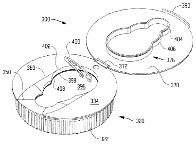
[0036] Figures 8-11 illustrate a third exemplary embodiment of a cap assembly
300, again a preferably molded plastic cap (such as a high density
polyethylene).
Likewise, and in a manner similar to the above-described embodiments, the cap
is
shown as a generally annular conformation, such as a body 320 having a
sidewall
322 that includes internal thread portions 324 operatively cooperating with
associated external thread portions on a container. The thread portions 324
may be
circumferentially spaced thread segments or thread lugs, or may be a
continuous
helical thread, for operative engagement with external threads or thread
portions of
the container. The cap may be threaded on to the shoulder of a container, or
alternatively may be manually pushed over the container threads.
Alternatively, no
threaded engagement may be used and the cap is simply snap-fit over a flange
and
subsequently fusion bonded to the container.
[0037] As is evident from a comparison of Figures 8-11 with Figures 1-7, many
of
the features of the earlier embodiments are included in this embodiment.
However,
one significant difference relates to the addition of a tear-away panel 396
that is
integrally molded with the cap. The panel is segregated about a periphery by a
frangible, thin walled portion 398 where the tear-away panel interconnects
with the
closing surface 334 of the cap. A tab, such as ring tab 400, is secured to the
tear-
away panel 396, and once a consumer opens the lid 370 of the cap assembly, by
rotating the lid about the hinge 372 to an open position (Figure 8), the tab
is exposed
and the consumer can remove the tear-away panel 396 by rupturing along the
frangible connection 398. Once the tear-away panel is removed, an opening is
formed in the cap assembly in much the same manner as shown with regard to the
earlier embodiments. Likewise, seal 376 extending from the underside of the
lid
surface 370 is dimensioned for a sliding fit along interconnecting wall 402
that
interconnects the tear-away panel (or opening once the tear-away panel is
removed)
relative to upper surface 334. Preferably, the seal includes a bead 404 having
a
slightly greater dimension than the sidewall 406 of the seal so that upon full
closure
of the lid relative to the body, the bead 404 slides along the interconnecting
wall until
CA 02737539 2011-03-17
WO 2010/033715 PCT/US2009/057336
bead 404 is snap-fit with a corresponding bead or flange 408 adjacent the
frangible
portion 398. In this manner, the lid provides a snap-fit connection with the
body,
either with the tear-away panel in place or after the tear-away panel has been
removed. The interference fit between the beads 404, 408, and the wall 406 of
the
seal with the interconnecting wall 402 provides for an original seal, and
subsequent
re-sealing of the contents of the fluid container. In this manner, tamper-
evident
protection is provided by way of the tear-away panel, i.e., a consumer can
readily
recognize if the tear-away panel is missing and that the contents of the
container
have been possibly compromised.
[0038] Use of the tear-away panel which may be easily removed by pulling
upwardly on the ring tab 400 and removing the panel 396 from the remainder of
the
cap assembly, advantageously eliminates the need for a separate foil seal,
gasket,
or similar structure. Stated another way, once the cap 300 is installed on the
container, and preferably fusion bonded thereto, the cap need not be removed
to
provide access to the container. Instead, the tear-away panel 396 is removed,
and
the lid and associated seal 376 used to seal and re-seal the opening formed in
the
cap body.
[0039] As is also evident in Figures 8-10, the interconnecting wall 402 may
vary
in height about its perimeter. That is, because of the first tapering region
360, and
the pour lip 350, the height of the interconnecting wall 402 may be slightly
larger
adjacent the hinge, and reduced in height as the interconnecting wall proceeds
about the perimeter toward the pour lip 350. In any event, the seal 376, and
particularly the bead 404 thereof, cooperates with bead 408 of the
interconnecting
wall to provide an effective seal from the external environment.
[0040] The disclosure has been described with reference to the preferred
embodiments. Obviously, modifications and alterations will occur to others
upon
reading and understanding the preceding detailed description. It is intended
that the
exemplary embodiment be construed as including all such modifications and
alterations in so far as they come within the scope of the appended claims or
the
equivalents thereof.