Note: Descriptions are shown in the official language in which they were submitted.
CA 02737603 2014-01-02
PIPELINE INSPECTION
BACKGROUND
[0002] The present application relates to the examination of pipelines or
other
fluid transport vessels (e.g., pipeline section, column, heat exchanger silo,
etc.)
using radiation. It finds particular application to the use of ionizing
radiation in
aboveground oil pipeline inspections. It also relates to other applications
where data
from a movable scanner may be used to provide information about the structure
and/or dynamics of an object being scanned.
[0003] Radiation, in general, penetrates an object under examination. The
object is exposed to radiation, and information is acquired based upon the
radiation
absorbed by the object, or rather an amount of radiation that is able to pass
through
the object. Typically, highly dense objects absorb more radiation than less
dense
objects. For example, a thick metal plate may absorb more radiation than a
thin
metal plate, and thus information related to various properties of the plates
(e.g.,
thickness, composition, etc.) may be acquired based upon the radiation that is
absorbed.
100041 Radiation devices commonly comprise a radiation source and a
detector array. The radiation source and detector array are typically
positioned on
substantially diametrically opposing sides of the object under examination.
Radiation, emitted from the radiation source, interacts with the object under
examination. Radiation that traverses the object is detected by the detector
array.
Data, produced based upon the detected radiation, may then be used to
determine
characteristics of the object under examination and/or used to produce an
image of
the object.
[0005] Inspection of pipelines is common to detect defects, obstructions,
and
other flaws in the manufacturing process that may affect the flow of a
1
CA 02737603 2011-03-17
WO 2010/033265
PCT/US2009/037085
fluid. Additionally, over time pipelines may endure abrasion, corrosion, etc.
that may lead to structural fatigue, divots, or cracks that cause the pipeline
to
leak or otherwise affect performance. Leakage of a fluid may lead to
substantial monetary cost and production delays for the entity responsible for
the pipeline, so the sooner defects, cracks, wall thinning, etc. can be
detected,
the better.
[0006] Radiation is utilized in the inspection process to measure
characteristics of a pipeline that are unable to be visually inspected. For
example, radiation provides a mechanism for measuring the thickness of a
pipeline's wall. While other mechanisms for measuring similar characteristics
have been devised, radiation works particularly well for some applications
because results are minimally affected by properties of the pipeline that are
not being measured, such as an insulation layer covering an external surface
of the pipeline's wall, for example. Additionally, unlike some other
mechanisms that measure characteristics from within the pipeline (e.g., a
"pig"), radiation devices may measure the characteristics from locations
external to the pipeline.
[0007] One type of radiation inspection device used to inspect pipelines is
disclosed in United States Patent 5,698,854 to Gupta. Gupta describes a
carriage configured to be moveably mounted to a pipeline and to
circumferentially enclose a scanning portion of the pipeline. As the carriage
slowly moves axially along a portion of the pipeline, a radiation source emits
radiation that may be detected by a detector array.
[0008] Another type of radiation inspection device used to inspect
pipelines
is disclosed in United States Patent 6,925,145 to Batzinger et al. Batzinger
et
al. describe a controller that causes a scanner to move along a pipeline. In
one embodiment, a radiation source and a detector array that are part of the
scanner are connected to an arcuate bracket that allows the radiation source
and detector array to be rotated while moving along the pipeline. However,
the Batzinger et al. device is deficient at least in that it does not allow
the
scanner to inspect a portion of the pipeline adjacent to, or rather touching,
a
pipe support.
2
CA 02737603 2014-01-02
[0009] While current radiation devices have proven useful in some
inspection
applications, there remains room for improvement. Obstructions (e.g., beams,
marking posts), directional changes in the pipeline, etc. prevent current
radiation
inspection devices from collecting data related to portions of the pipeline
that are in
close proximity to the obstruction, such as portions touching and/or nearby
the
obstruction. Obstructions also make it difficult and/or impossible for some
radiation
inspection devices to travel past the obstruction and continue scanning
without the
device being disconnected from the pipe and then reassembled on the other side
of
the obstruction. Some radiation inspection devices are also not configured to
rotate
in a transverse, or rather radial, direction with respect to the pipeline,
making it more
difficult to acquire accurate and/or reliable data for various portions of the
pipeline.
Additionally, some of the radiation inspection devices require significant
human
intervention (e.g., piloting the device as it moves axially along the
pipeline) which
may make operation of a device very costly. The slow speed at which some
radiation inspection devices move axially along a pipeline also poses a
problem in
some applications because it takes too long to scan a meaningful length (e.g.,
thousands of miles) of the pipeline.
SUMMARY
[0010] A pipe inspection apparatus is disclosed. The apparatus may
comprise a carriage configured for movement along a stationary pipe and an
ionizing
radiation source. The apparatus may also comprise a radiation detector carried
by
the carriage. The detector may detect radiation from the source, which
radiation has
traversed a pipe support and a wall of the pipe.
[0011] A method is also disclosed. The method may comprise using a
scanning apparatus that travels along a pipeline to detect ionizing radiation
that has
traversed a wall of the pipeline and an obstacle that substantially impedes
the
motion of the scanning apparatus along the pipeline. The method may also
comprise
using the detected radiation to generate information indicative of a
characteristic of
the pipeline.
3
CA 02737603 2015-01-28
95224-1
[0012] Also disclosed is an apparatus for scanning a pipe that may be
supported by first and second axially-spaced transverse supports. The
apparatus
may comprise a scanner configured to scan the pipe at the first and second
supports
and therebetween. The apparatus may also comprise a carriage configured to
mount
to an exterior of the pipe and to carry the scanner between the first and
second
supports.
[0012a] According to an aspect of the invention there is provided a
pipe
inspection apparatus comprising: a carriage configured to be mounted to a pipe
and
configured for movement along the pipe, the carriage comprising; a
substantially
c-shaped member configured for rotation relative to the pipe about an axis of
rotation
extending in direction parallel to an axial direction of the pipe; an ionizing
radiation
source coupled to the c-shaped member; and a radiation detector coupled to the
c-shaped member and positioned substantially diametrically opposite the
ionizing
radiation source relative to the pipe, the radiation detector extending beyond
the
c-shaped member in the axial direction to facilitate positioning a support
beam, to
which the pipe is mounted and generally transverse to the pipe, between a
portion of
the radiation detector and the pipe and to facilitate an examination of a
portion of the
pipe in contact with the support beam.
[0012b] According to another aspect of the invention there is provided
a method
for inspecting a pipe via ionizing radiation, comprising: while mounted to the
pipe,
performing a helical scan of the pipe by rotating an ionizing radiation source
and a
radiation detector about an axis of rotation extending in a direction parallel
to an axial
direction of the pipe and moving a carriage supporting the ionizing radiation
source
and the radiation detector in a first direction parallel to the axial
direction; and upon
encountering a support beam extending in a direction transverse to the axial
direction, halting the rotating and the moving and positioning the radiation
detector in
a first position relative to the support beam such that the support beam is
between
the pipe and a portion of the radiation detector to facilitate an examination
of a
portion of the pipe in contact with the support beam.
[0012c] According to another aspect of the invention there is provided a
pipe
inspection apparatus comprising: a carriage configured for movement along a
pipe,
4
= CA 02737603 2014-01-02
the carriage comprising: a substantially c-shaped member configured for
rotation
relative to the pipe about an axis of rotation extending in a direction
parallel to an
axial direction of the pipe; an ionizing radiation source coupled to the c-
shaped
member; and a radiation detector coupled to the c-shaped member and positioned
substantially diametrically opposite the ionizing radiation source relative to
the pipe,
the radiation detector extending beyond the c-shaped member in the axial
direction
to facilitate positioning a support beam to which the pipe is mounted between
a
portion of the radiation detector and the pipe and to facilitate an
examination of a
portion of the pipe in contact with the support beam, the support beam
extending in a
direction substantially transverse to the axial direction of the pipe, and
wherein: the
c-shaped member is configured to rotate to a first position relative to the
support
beam to facilitate the examination of the portion of the pipe in contact with
the
support beam, and the c-shaped member is configured to rotate to a second
position
relative to the support beam to facilitate traversing the portion of the pipe
in contact
with the support beam.
[0013] Those of ordinary skill in the art will appreciate still
other aspects of the
present application upon reading and understanding the appended description.
FIGURES
[0014] The application is illustrated by way of example and not
limitation in
the figures of the accompanying drawings, in which like references indicate
similar
elements and in which:
100151 Fig. 1 is a schematic block diagram illustrating an example
apparatus
for inspecting a pipe.
[0016] Fig. 2 illustrates an example apparatus for inspecting a
pipe viewed
from a transverse plane.
[0017] Fig. 3 illustrates an example detector array.
[0018] Fig. 4 illustrates an example method for generating
information
indicative of a characteristic of a pipe.
4a
= CA 02737603 2014-01-02
,
[0019] Fig. 5 illustrates an example apparatus, viewed from an
axial plane,
that is moving along a portion of a pipe and encountering an obstacle.
[0020] Fig. 6 illustrates an example apparatus, viewed from an
axial plane,
that is moving along a portion of a pipe and encountering an obstacle.
[0021] Fig. 7 illustrates an example apparatus, viewed from an
axial plane,
that is moving along a portion of a pipe and encountering an obstacle.
4b
CA 02737603 2011-03-17
WO 2010/033265
PCT/US2009/037085
[0022] Fig. 8 illustrates a pipe supported by a first and second pipe
support.
[0023] Fig. 9 illustrates a detector located at a first transverse angle
with
respect to a pipe.
[0024] Fig. 10 illustrates a detector near an obstacle and located at a
first
transverse angle with respect to a pipe.
[0025] Fig. 11 illustrates a detector located at a second transverse angle
with respect to a pipe.
[0026] Fig. 12 illustrates a detector near an obstacle and located at a
third
transverse angle with respect to a pipe.
[0027] Fig. 13 illustrates a detector located at a fourth transverse angle
with respect to a pipe.
[0028] Fig. 14 illustrates a detector near an obstacle and located at a
fifth
transverse angle with respect to a pipe.
[0029] Fig. 15 illustrates a detector located at a sixth transverse angle
with
respect to a pipe.
[0030] Fig. 16 illustrates a detector near an obstacle and located at a
seventh transverse angle with respect to a pipe.
[0031] Fig. 17 illustrates a detector located at an eighth transverse angle
with respect to a pipe.
[0032] Fig. 18 illustrates a detector near an obstacle and located at a
first
transverse angle with respect to a pipe.
DESCRIPTION
[0033] Fig. 1 is a system block diagram illustrating an example apparatus
100 for generating information indicative of one or more characteristics
(e.g.,
wall thickness, positions of pits or divots, etc.) of a stationary pipe, or
rather a
pipeline, based upon radiation that has traversed the pipe. While the
apparatus 100 may be used with pipes of various dimensions, the apparatus
100 finds particular application with hydrocarbon, or rather oil pipes. These
CA 02737603 2011-03-17
WO 2010/033265
PCT/US2009/037085
pipes are typically about five to eight inches in diameter, comprise two to
three inches of foam insulation, are covered with twenty to twenty-four gauge
steel wrapping, and have a wall thickness between 0.250 and 0.500 inches.
[0034] The example apparatus 100 comprises a carriage 102 (e.g., a data
taking head) configured for movement along the stationary pipe. The carriage
102 may be physically attached to the pipe (e.g., on tracks) and/or may be
rested on the pipe (e.g., by gravity), but the carriage 102 is generally not
in
contact with surfaces other than the pipe, such as the ground, for example,
while it is in motion.
[0035] The carriage 102 may be propelled along the stationary pipe
through a mechanism external to the carriage (e.g., a pulley system, etc.)
and/or the carriage may be self-propelled. In one embodiment, the carriage
102 comprises a carriage drive mechanism 104 configured to propel the
carriage 102 in an axial direction along a portion of the pipe. It will be
appreciated that the term "axial" generally refers to a direction along the
length of the pipe, the direction of fluid flow within the pipe and/or a plane
parallel to either of these directions. Likewise, the term "transverse" refers
to
a direction that cuts across the axial direction. That is, "transverse" can be
said to correspond to a plane perpendicular to the length of the pipe and/or
to
the direction of fluid flow along the length of the pipe.
[0036] A radiation source 108 and a radiation detector 110 may be
operably coupled the carriage 102. The source 108 is configured to emit
radiation in a pyramidal, wedge, fan, or other shaped beam. In a preferred
embodiment, the emitted radiation is ionizing radiation. In one example, the
radiation source 108 is a gamma ray source sized to provide an adequate
number of gamma rays based upon characteristics of the pipe (e.g., its
composition).
[0037] The amount of radiation emitted and/or the trajectory of the emitted
radiation may be predetermined based upon the desired movement of the
carriage 102, for example. In one example, the radiation source 108 emits a
beam of radiation having an axial dimension greater than or equal two twice
the diameter of the pipe being inspected to promote speed. An axial
6
CA 02737603 2011-03-17
WO 2010/033265
PCT/US2009/037085
dimension greater than or equal two twice the diameter of the pipe may allow
the carriage to move at a speed of about two inches per second to a speed of
about 75 inches per second, for example. The source 108 may also be
configured to emit radiation from a focal spot that is sized and/or shaped
similar to an element or channel of the detector 110 (e.g., making
mathematical modeling easier).
[0038] The radiation detector 110 may be situated in an axial plane that is
on a diametrically opposing side of the pipe from the source 108 (e.g., the
detector 110 is about 180 away from the source 108). In this way, the
detector 110 may detect radiation, emitted from the source 108, after the
radiation has traversed a wall of the pipe. It will be understood to those
skilled
in that art that the radiation detector 110 may be a direct conversion
detector
such as cadmium zinc telluride scintillator-based detector, or it may be an
indirect conversion detector such as a CdW04 crystal detector or other
scintillator-based detector, for example. It will also be understood to those
skilled in the art that the detector 110 may be a multi-element detector
configured to resolve a pyramidal shaped beam of radiation emitted from the
radiation source 108 into many small sub-beams (e.g., to improve the quality
of data generated based upon the detected radiation).
[0039] The detector 110 may be configured based upon the desired
movement of the carriage 102 and/or the object being scanned. For example,
to promote speed, the detector 110 may have an axial dimension that is at
least two times greater than its transverse dimension. The detector 110 may
also be configured to resolve a spatial resolution between about 0.5 and 1.0
times the wall thickness of the pipe being scanned. That is, the detector 110
may be configured to detect when the pipe's wall that has deteriorated to less
than one-half of its original thickness in a particular area, for example.
[0040] The detector 110 may also be configured to counterbalance the
weight of the radiation source 108. In one example, the radiation source 108,
including a radiation shield, and the detector 110 are configured for
transverse
motion about the pipe (e.g., to rotate about the pipe), and the detector 110
comprises a counterweight so that the center of mass of the radiation source
7
CA 02737603 2011-03-17
WO 2010/033265
PCT/US2009/037085
108 and the detector 110 is substantially coincident with a center of the
transverse motion (e.g., an axis of rotation).
[0041] The carriage drive mechanism 104, the radiation source 108, and/or
the detector 110 may be operably coupled with a first data transceiver 112.
The first data transceiver 112 may transceive (e.g., send and/or receive) data
related to the carriage drive mechanism 104, the radiation source 108, and/or
the detector 110 (collective referred to as the "devices"). In one embodiment,
the first data transceiver 112 receives data from one or more devices and
transmits it to a second data transceiver 114 located remotely (e.g., on a
remote station one hundred yards from the pipe). The second data
transceiver 114 may also transmit data to the first data transceiver 112,
wherein the first data transceiver 112 sends the data to its designated
device.
[0042] The apparatus 100 may also comprise a remote station 116
configured for monitoring one or more carriages. In one embodiment, the
remote station 116 is part of a truck or other motor vehicle that is mobile
relative to the carriage 102. By way of example only, and not limitation, the
remote station 116 may be moved while the carriage is moving along the pipe
so that a substantially consistent distance is maintained between the remote
station 116 and the carriage 102 (e.g., one hundred yards there-between).
The remote station 116 may comprise a computer having a graphical user
interface 118 configured to display information related to the one or more
carriages, such as their respective trajectories and/or display information
related to other components comprised within the remote station 116. For
example, the graphical user interface 118 may display a wall thickness of a
portion of the pipe based upon calculations made by a data collection
mechanism 120 and/or display whether radiation from the radiation source
108 is detected by a radiation measuring device 119 within the remote station
116 (e.g., to mitigate the possibility of radiation exposure to human
inspectors
near the remote station 116).
[0043] The remote station 116 may also comprise the data collection
mechanism 120 and/or the second data transceiver 114. In one embodiment,
the second data transceiver 114 receives data from the first data transceiver
112 and transmits it to the data collection mechanism 120. The data
8
CA 02737603 2011-03-17
WO 2010/033265
PCT/US2009/037085
collection mechanism 120 may use the received data to determine one or
more characteristics of the pipe, create a report based upon those
determinations, and/or issue an alert if the determined characteristic(s) are
outside a specified range. For example, when one or more determined
characteristics are outside of a specified range, the data collection
mechanism 120 may create a report that contains the measured value(s), the
dimensions of an affected area(s), and the location of the affected area(s)
along the pipe (e.g., so that a weak spot in the pipe may be repaired).
[0044] It will be appreciated that the second data transceiver 114 may also
be configured to transceive data related to a controller 122. In one example,
the controller 122 receives positional data from the carriage 102 and the
controller 122 is configured to map the trajectory of the carriage 102 along
the
pipe. It will be appreciated that controller may also send commands to the
carriage 102 (e.g., through the first and second data transceivers 112 and
114).
[0045] The second data transceiver 114 may also be configured to send
data, such as reports containing information about troubled spots of the pipe,
to a third data transceiver 124 attached to a central station 126 and/or
receive
data, such as maps depicting the pipe, from the third data transceiver 124. In
one example, the third data transceiver 124 may also register a fault if the
remote station 116 does not transmit to it within a given period of time so
that
emergency help may be dispatched. This may be particularly useful in
Alaska, for example, where there is vast wilderness and extreme cold.
[0046] It will be appreciated that in some applications it may be more
beneficial to not have a remote station 116 and/or a central station 126. In
those applications some of the aforementioned devices, components,
mechanisms, etc. may be situated differently. For example, the data
collection mechanism 120 may be attached to the carriage 102 and/or the
controller 122 may be located at the central station 126. Additionally, some
of
the aforementioned devices, components, mechanisms, etc. may have less
applicability depending upon the circumstances.
9
CA 02737603 2011-03-17
WO 2010/033265
PCT/US2009/037085
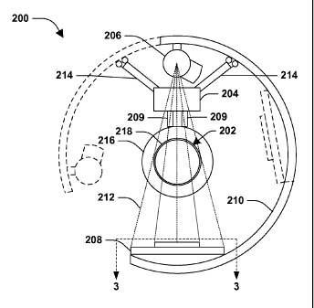
[0047] Fig. 2 illustrates a transverse plane of an example apparatus 200
configured to move axially along a stationary pipe 202 (e.g., going into and
out of the page). The apparatus 200 comprises a carriage 204 (e.g., 102 in
Fig. 1), a radiation source 206 (e.g., 108 in Fig. 1), and a detector 208
(e.g.,
110 in Fig. 1). In the illustrated example, the carriage 204 moves axially
along
the pipe 202 by wheels 209 that couple the carriage to the pipe (e.g., the
wheels 209 of the carriage 204 rest on top of the pipe 202).
[0048] In Fig. 2, the carriage 204 is operably coupled to the radiation
source 206 and the detector 208 through a substantially arcuate, or rather c-
shaped member 210. As illustrated by dotted lines, the c-shaped member
may be configured to rotate about the pipe 202 in a generally transverse
motion along guide rails 214, for example, physically attached to the carriage
204. That is, the c-shaped member 210 may rotate clockwise and/or
counterclockwise about the pipe 202 through a plane substantially
perpendicular to the direction of flow of fluid in the pipe 202 (into and/or
out of
the page). In this way, objects attached to the c-shaped member 210, such
as the radiation source 206 and/or the detector 208, may rotate about the pipe
202 to inspect the pipe 202 from a plurality of angles or views.
[0049] It will be appreciated that in other embodiments, that the carriage
204 may not be coupled to the c-shaped member 210 and/or the detector 208
may not be rotated by the c-shaped member 210. In one example, the
detector is directly attached to the carriage 204, and the carriage 204 is
configured to rotate in a helical pattern through a plurality of axial and
traverse
planes relative to the pipe 202.
[0050] In some applications, the pipe 202 may comprise an insulation layer
216 configured to protect fluid traveling through the pipe from nature's
elements. For example, pipes running through the Alaskan wilderness often
comprise a layer of insulation to prevent fluid inside the pipe 202 from
freezing. Generally in these applications, the pipe wall 218 has a thickness
of
between about .250 and about .500 inches, and the layer of insulation has a
thickness of between about 2 and about 3 inches.
CA 02737603 2011-03-17
WO 2010/033265
PCT/US2009/037085
[0051] While the insulation layer 216 serves to protect fluid inside the
pipe
202, it also hampers that ability to inspect the pipe 202. For example, as
portions of the interior surface of the pipe wall 218 deteriorate and break
away, the fluid carries the particles downstream. Therefore, more radiation
will be detected in areas where the interior surface of the pipe wall 218 has
a
pit, divot, or other non-uniformity than in areas where little to no
deterioration
has occurred. However, portions of the exterior surface of the pipe wall 218
that deteriorate and would otherwise break away may be held in place by the
insulation layer 216. Therefore, a substantially equal amount of radiation
will
be detected in an area where the exterior surface has significantly
deteriorated and in an area where the exterior surface has experienced little
to no deterioration, making detection of the exterior deterioration difficult.
[0052] Fig. 3 illustrates one means of detecting deterioration on both the
interior and exterior surfaces of a pipe wall (e.g., 218 in Fig. 2). More
particularly, Fig. 3 illustrates an example detector 300 (e.g., 208 of Fig. 2
taken along phantom lines 3-3) of a pipe inspection apparatus (e.g., 100 in
Fig. 1). The detector 300 comprises two detector arrays, a first array 302 and
a second array 304. It will be understood to those skilled in that art that
each
array of the detector 300 may comprises a plurality of smaller detectors, or
rather detector elements or channels (e.g., represented as small squares or
rectangles), configured to detect small beams of radiation that have traversed
the pipe (e.g., 202 in Fig. 2). The first array 302 may be configured to
detect
radiation indicative of the interior surface of the pipe wall. The second
array
304, separated from the first array 302 by a gap 306, may be configured to
detect radiation indicative of protrusions (e.g., external rust) on the
exterior
surface of the pipe wall. In the illustrated example, the second array 304 is
narrower in the transverse dimension than the first array 302 in order to
improve radial resolution (e.g., to detect non-uniformities that would
otherwise
be undetectable due to the presence of insulation that keeps outer surface
rust, etc. in place). It will be appreciated that radiation indicative of the
outer
surface (e.g., detected by the second array 304) and radiation indicative of
the
inner surface (e.g., detected by the first array 302) may be combined or
otherwise compared (e.g., by a data collection mechanism similar to 120 in
11
CA 02737603 2011-03-17
WO 2010/033265
PCT/US2009/037085
Fig. 1) to determine characteristics of the wall (e.g., how thick the wall is
at a
given point along the pipe).
[0053] Returning to Fig. 2, occasionally, the pipe 202 may be supported by
a pipe support. For example, hydrocarbon, or oil, pipes are commonly
supported on a plurality of pipe supports. In this way, the pipes are located
above and substantially parallel to the ground. To provide a more complete
inspection of the pipe 202, the radiation detector 208 is configured to detect
radiation 212 that has traversed both a pipe support and the pipe wall 218
(e.g., supported by the pipe support). That is, as the carriage 204 moves
along the pipe 202 and encounters a pipe support, the detector 208 is
configured to detect radiation 212 that has passed through a pipe support as
well as a portion of the pipe wall 218 adjacent to, or in close proximity to
(e.g.,
touching/supported by) the pipe support. For example, the detector 208 may
be positioned substantially beneath the pipe 202 and may be configured to
pass beneath a portion of the pipe support. It will be appreciated that the
term
"portion" is used herein in a broad sense and intended to include any and all
of the object the term "portion" is being used to describe (e.g., the detector
may be configured to pass beneath the entire pipe support or just some or a
part of the pipe support).
[0054] Fig. 4 illustrates a method 400 for generating information
indicative
of a characteristic of a pipe. While the method 400 is illustrated and
described below as a series of acts or events, the present disclosure is not
limited by the illustrated ordering of such acts or events. For example, some
acts may occur in different orders and/or concurrently with other acts or
events apart from those illustrated and/or described herein. In addition, not
all
illustrated acts may be required. Further, one or more of the acts depicted
herein may be carried out in one or more separate acts or phases.
[0055] The method 400 starts at 402, and a scanning apparatus that
travels axially along a pipe, or rather a pipeline, is used to detect ionizing
radiation that has traversed a wall of the pipe and an obstacle, such as a
pipe
support, that substantially impedes the motion of the scanning apparatus
along the pipe at 404.
12
CA 02737603 2011-03-17
WO 2010/033265
PCT/US2009/037085
[0056] At 406, the detected radiation is used to generate information
indicative of a characteristic of the pipe, such as a thickness of a wall of
the
pipe, for example. The method ends at 408.
[0057] To illustrate a specific example of how Fig. 4's method could be
implemented, Fig. 4 is discussed with reference to a series of system
diagrams in Figs. 5-18.
[0058] Figs. 5-7 illustrate an example apparatus 500 (e.g., 200 in Fig. 2)
as
it moves axially along a stationary pipe 502 (e.g., 202 in Fig. 2). More
particularly, Fig. 5 shows a carriage 504 (e.g., 204 in Fig. 2)
travelling/moving
(e.g., via wheels 505) axially along a pipe 502 and approaching a pipe support
514 or other obstacle. Operably coupled to the carriage 504 are a radiation
source 506 (e.g., 206 in Fig. 2) and a radiation detector 508 (e.g., 208 in
Fig.
2). In the illustrated example, the source 506 and detector 508 are physically
coupled to the carriage 504 through a c-shaped member 518 (e.g., 210 in Fig.
2). Radiation 512 (e.g., 212 in Fig. 2) that traverses the pipe 502 is
detected
by the radiation detector 508 situated on a substantially diametrically
opposing side of the pipe 502 from the radiation source 506.
[0059] The support 514 is generally transverse to the pipe 502 (e.g., the
support 514 is going into and out of the page) and the apparatus 500 is
configured to allow a portion of the support 514 to fit between the apparatus
500 and the pipe 502. In the illustrated example, the apparatus 500
comprises a substantially material free region 516 that allows a portion of
the
apparatus 500 to be positioned with respect to the support 514 to detect
radiation 512 from the source 506 that has traversed both the support 514
and the pipe 502. In Fig. 5, the substantially material free region 516 is a
region between the detector 508 and the pipe 502, wherein the detector 508
is spaced away from the pipe 502 a distance that allows the support 514 to fit
between the pipe 502 and the detector 508. It will be understood to those
skilled in the art the other configurations for creating a substantially
material
free region 516 are also contemplated. In one example, the substantially
material free region 516 is a region between the source 506 and the pipe 502
(e.g., the locations of the source 506 and the detector 508 are reversed).
13
CA 02737603 2011-03-17
WO 2010/033265
PCT/US2009/037085
[0060] Fig. 6 illustrates the example apparatus 500 encountering, or rather
in close proximity to the pipe support 514 while the carriage 504 is moving
axially to the right 520. In the illustrated example, the support 514 is
located
beneath and substantially adjacent to the pipe 502. The apparatus 500 is
configured so that the detector 508 passes beneath a portion of the support
514 during a time when the detector 508 detects radiation from the source
506. That is, the apparatus 500 is positioned in such a way that a portion of
the support 514 or other obstacle is in the substantially material free region
516 of the apparatus 500. While the support 514 is in the substantially
material free region 516, the source 506 may emit radiation 512 that traverses
a wall of the pipe 502 and a portion of the support 514, and is then detected
by the detector 508.
[0061] It will be understood to those skilled in the art that there are
numerous ways of creating a substantially material free region such as that
illustrated in Figs. 5-7. In the illustrated example, the detector 508 has a
wider axial dimension than the axial dimension of the c-shaped member 518.
In this way, the detector 508 can slide, or rather be position beneath the
support 514, even while the c-shaped member 518 abuts or is blocked by the
support 514. In another example, the detector 508 is offset from a c-shaped
member 518 or other bracket supporting the detector 508, thus allowing the
detector 508 to be positioned under the support 514 regardless of whether the
axial movement of the c-shaped member is impeded by the support 514.
[0062] Fig. 7 illustrates the example apparatus 500 after radiation 512
that
has traversed a wall of the pipe 502 and the pipe support 514 has been
detected. In the illustrated example, the apparatus 500 has reversed direction
(e.g., now moving axially to the left 522) after detecting radiation 512 that
traversed both the pipe 502 and the pipe support 514. It will be understood to
those skilled in that art that by repeatedly moving in a first direction
(e.g., to
the right 520 as illustrated in Fig. 6) and then altering, or rather reversing
direction (e.g., by moving to the left 522 as illustrated in Fig. 7), the
detector
508 may make a plurality of passes along a length of the pipe 502 during a
time when the detector 508 is detecting radiation 512 from the source 506. In
14
CA 02737603 2011-03-17
WO 2010/033265
PCT/US2009/037085
this way, the detector 508 may take multiple readings along a particular
length
of the pipe 502.
[0063] As illustrated in Fig. 8, the pipe may be supported by first and
second axially-spaced pipe supports 812 and 814 (e.g., 514 in Fig. 5). A
scanning apparatus (e.g., 500 in Fig. 7) may be configured to scan the pipe
802 (e.g., 502 in Fig. 7) at the first and second supports 812 and 814 and
therebetween. That is, a carriage (e.g., 504 in Fig. 7) may be configured for
movement between the first and second supports 812 and 814 and a radiation
source (e.g., 506 in Fig. 7) may be configured to emit radiation (e.g., 512 in
Fig. 7) substantially continuously during movement. In this way, the length of
pipe 802 between the first and second supports 812 and 814, and the portions
of the pipe 802 supported on the first and second supports 812 and 814 may
be inspected. In one embodiment, the apparatus scans the length of pipe 802
between the first and second supports 812, 814 in a first direction 804 and
then scans the same length of pipe in a second direction 806 (e.g., in a back
and forth motion).
[0064] With reference back to Fig. 2, it will be appreciated that the
detector
208 and/or the radiation source 206 may be configured to rotate in a
transverse motion (e.g., around the pipe) as the apparatus 200 moves axially
along the length of the pipe 202 (e.g., as illustrated in Fig. 8) to detect
data
indicative of a plurality of views of the pipe 202. In one example, the
detector
208 rotates in a helical or spiral-like manner as the apparatus 200 moves
along the pipe 202. In another example, the detector 208 is fixed at a first
transverse angle (e.g., relative to the pipe) as the apparatus 200 moves in a
first direction (e.g., 804 in Fig. 8) and is fixed at a second transverse
angle as
the apparatus 200 moves in a second direction (e.g., 806 in Fig. 8). That is,
the detector 208 is scanned back and forth, but at different transverse angles
for respective scans (e.g., thereby tracking a zig-zag pattern).
[0065] Figs. 9-18 illustrate movement of an example scanning apparatus
(e.g., 500 in Fig. 5) to scan a length of pipe including at first and second
axially-spaced pipe supports 812 and 814. It will be appreciated that a
detector 808 of the apparatus moves through a plurality of transverse angles
as the pipe is scanned. It will also be understood that this movement allows
CA 02737603 2011-03-17
WO 2010/033265
PCT/US2009/037085
radiation indicative of the pipe 802 to be obtained from a plurality of
different
views, which promotes accurate measurements. In one embodiment, the
radiation, indicative of the pipe 802 from a plurality of angles, may be
combined using computed tomography techniques known to those skilled in
the art to create images of the pipe 802 being scanned. However in some
applications, such as when the apparatus is measuring wall thickness, for
example, an image may not be produced (e.g., because it is not necessary for
determining the characteristic being measured). It will also be appreciated
that some transverse angles illustrated in Figs. 9-18 may not be suited for
instances in which the detector 808 is in close proximity to the supports
because the detector 808, for example, may make physical contact with the
obstacle (e.g., preventing the apparatus from continuing its scan). That is,
at
some transverse angles the detector 808 may be unable to be positioned
about the obstacle to detect radiation that has traversed both a wall of the
pipe 802 and the obstacle (e.g., a pipe support) and/or positioned such that
the detector's movement is otherwise unimpeded by the obstacle.
[0066] As illustrated in Fig. 9, while moving in a first direction 804
(e.g.,
away from support 812 and toward support 814) the detector 808 may be
located at a first transverse angle (e.g., with respect to the pipe). When the
detector 808 reaches the second support 814, the detector 808 may continue
moving in the first direction 804, with the detector 808 located at the first
transverse angle, as illustrated in Fig. 10. This arrangement effectively
allows
the scanning apparatus to pass over the second support 814.
[0067] Once the detector 808 has detected radiation that has traversed a
portion of the pipe 802 in close proximity to the second support 814 (e.g., a
portion of the pipe 802 on top of the second support 814), the detector 808
may reverse direction and start moving in a second direction 806. Once the
detector 808 has moved far enough along in the second direction 806 such
that it has cleared or is no longer over top of the second support 814 (recall
that the detector 808 has a somewhat substantial axial length into and/or out
of the page), the detector's position may be changed, or rather rotated (e.g.,
72 degrees from the first transverse angle), to a second transverse angle
(e.g., without bumping into the second support 814), as illustrated in Fig.
11.
16
CA 02737603 2011-03-17
WO 2010/033265
PCT/US2009/037085
It will be appreciated that motion in the axial direction may be halted while
transverse movement occurs as provided herein.
[0068] After being rotated to the second transverse angle, the detector 808
may continue moving along the pipe in the second direction 806 until it
reaches the first support 812. When the detector 808 reaches the first
support 812, the detector 808 may be (halted and then) rotated again (e.g., 90
degrees from the first transverse angle) to a third transverse angle so that
the
first support 812 does not impede the detector from continuing movement in
the second direction 806 (e.g., so that the detector 808 does not bump into
the first support 812), as illustrated in Fig. 12.
[0069] After being rotated through to the third transverse angle, the
detector 808 may then continue moving in the second direction 806 so that a
portion of the first support 812 is situated between the detector 808 and the
pipe 802 (e.g., a portion of the detector 808 is under the first support 812).
This allows radiation 820 that has traversed both the support 812 and the pipe
802 to be detected by the detector 808. The detector 808 may then reverse
direction and start moving in the first direction 804. When the detector 808
has cleared the first support 812 (e.g., is no longer under the first support
812), the detector 808 may be rotated (e.g., 144 degrees from the first
transverse angle) to a fourth transverse angle, as illustrated in Fig. 13, and
may continue moving in the first direction 804 until it reaches the second
support 814. It will be appreciated that the supports 812, 814 are not
illustrated in Figs. 9, 11, 13, 15 and 17 since the detector 808 is not in as
close proximity to the supports 812 or 814 as compared to the orientations
illustrated in Figs. 10, 12, 14, 16 and 18 where the detector 808 has
"reached"
the supports 812 or 814.
[0070] When the detector 808 reaches the second support 814, the
detector 808 may be rotated again (e.g., 180 degrees from the first transverse
angle) to a fifth transverse angle that does not impede the detector 808 from
continuing movement in the first direction 804, as illustrated in Fig. 14. The
detector 808 may then continue moving in the first direction 804 to detect
radiation that has traversed a portion of the pipe 802 in close proximity to
the
second support 814. Note, however, that unlike the orientation illustrated in
17
CA 02737603 2011-03-17
WO 2010/033265
PCT/US2009/037085
Fig. 10, a c-shaped member of the apparatus (e.g., which supports the
detector 808 and a radiation source 810) is impeded by the second support
814. However, the (elongated) shape of the detector 808 (e.g., into and out of
the page) still allows the portion of the pipe 802 directly above the second
support 814 to be scanned. Accordingly, at this juncture, in the example
illustrated, the portion of the pipe 802 resting upon the second support 814
has been scanned at two different transverse angles that happen to be180
apart. That is, the orientation of the source 810 and the detector 808 is
reversed in Figs. 10 and 14. These different "views" contribute to better
insight or fidelity into the wear of the pipe 802 (e.g., coupled with
additional
data or information about the pipe).
[0071] The detector 808 may then reverse direction and start moving in the
second direction 806. When the detector 808 has cleared the second support
814, the detector 808 may be rotated (e.g., 216 degrees from the first
transverse angle) to a sixth transverse angle, as illustrated in Fig. 15, and
may continue moving in the second direction 806 until it reaches the first
support 812. When the detector 808 reaches the first support 812, the
detector 808 may be rotated again (e.g., 270 degrees from the first transverse
angle) to a seventh transverse angle that does not impeded the detector from
continuing movement in the second direction 806, as illustrated in Fig. 16.
The detector 808 may then continue moving in the second direction 806 to
detect radiation that has traversed a portion of the pipe 802 in close
proximity
to the first support 812. In the illustrated example, the first support 812 is
situated between the source 810 and the pipe 802 (e.g., the source 810 is
under the first support 812). This allows radiation 820 that has traversed
both
the support 812 and the pipe 802 to be detected by the detector 808. Similar
to the preceding discussion regarding Figs. 10 and 14, in this example, the
portion of the pipe 802 resting upon the first support 812 has now been
"viewed" from two different angles that happen to be180 apart, once in Fig.
12 and again in Fig. 16.
[0072] The detector 808 may then reverse direction and move in the first
direction 804. When the detector 808 has cleared the first support 812, the
detector 808 may be rotated (e.g., 288 degrees from the first transverse
18
CA 02737603 2011-03-17
WO 2010/033265
PCT/US2009/037085
angle) to an eighth transverse angle, as illustrated in Fig. 17, and may
continue moving in the first direction 804 until it reaches the second support
814 (thus acquiring yet another "view" of the pipe 802 at locations between
the first 812 and second 814 supports). When the detector 808 reaches the
second support 814, the detector 808 may be rotated again to the first
transverse angle, as illustrated in Fig. 18 (which is also the original
orientation
illustrated in Fig. 10). That is, this section of pipe, including at first and
second support 812, 814 locations, may be sufficiently scanned such that the
apparatus is reset to its original orientation. The detector 808 may then move
to another section of the pipe 802 positioned between the second support 814
and a third support, and repeat the acts herein described between the second
support 814 and the third support.
[0073] It will be appreciated that while Figs. 9-18 illustrate the detector
808
rotating substantially 360 about a pipe 802, the detector 808 and/or another
portion of the apparatus, such as the radiation source 810, may be configured
to rotate less than or equal to 360 about the pipe 802. In one example, the
total range of traverse angles through which the detector 808 is varied does
not exceed about 180 (e.g., the detector 808 never rotates about the entire
circumference of the pipe 802). In another example, the total range of
rotation
the detector 808 makes is substantially beneath the pipe 802(e.g., the
detector 808 may never rotate to the side and/or above or over top of the pipe
802). Merely scanning the bottom of the pipe may be sufficient in some
instances because that is where the majority of wear and tear occurs, given
that fluid flow primarily occurs in the bottom or lower part of the pipe.
Nevertheless, the particular transverse angles and movements described
herein are merely examples, and the apparatus can move in any desired
manner to acquire radiation and generate information therefrom indicative of a
characteristic of the pipeline, including at locations where the pipeline is
adjacent to, in contact with and/or otherwise supported by cross-braces or
other types of pipe supporting structures, without having to be removed from
the pipe.
19