Note: Descriptions are shown in the official language in which they were submitted.
CA 02737626 2011-03-18
WO 2010/036331 PCT/US2009/005279
INSECT ERADICATION SYSTEM AND METHOD
Inventors: Christopher Molnar, Paul Rannick, and Tom Jarzynka
BACKGROUND
Bed bugs are nocturnal insects that feed only on blood, mainly on the blood of
humans. Bed
bugs will suck blood from other animals, such as domestic pets, as well as
pests such as birds and
bats. They live in loose groups or individually and have a tendency to occupy
cracks and crevices or
other similar harborages. Bed bugs are stimulated to seek a host most likely
by vibrations, body
heat, and C02 vapors. An inseminated adult female bed bug requires a blood
meal within five days
either before or after insemination for egg laying to occur. Once fed and
inseminated, the female bed
bug locates a suitable environment and deposits small, whitish eggs, which are
attached with a
cement-like material to surfaces in the cracks and crevices where they hide.
Eggs can be found in
caches in protected areas as well as individually in open spaces. Females
typically lay 2-3 eggs per
day and can lay 200 to 500 eggs in their lifespan. Under appropriate
temperatures, eggs hatch after
approximately 10 days but may be viable for as long as 28 days before
hatching. Bed bug nymphs
molt 5 times before reaching adulthood and require a blood meal prior to each
molt. Adults can live
without a meal for several months (in some reports, for more than a year) and
nymphs for up to four
months without feeding.
The time for development of each instar is dependant upon and available food
source (host),
temperature and humidity. With an available host, the ideal environment for
development is 83 F to
90 F with 75% to 80% relative humidity. Under these conditions, all five nymph
stages can be
completed and sexual maturity reached in approximately 45-60 days. There is
potential for 3-4
generations per year to be produced.
During the nymphal development stages, bed bugs may feed as frequently as once
a day and
usually feed at night when people are asleep; however, they will seek blood
meals during the day
under subdued or low light situations. It takes 3 to 12 minutes to feed to
engorgement. To feed, the
proboscis (piercing mouthpart) penetrates the skin and a feeding tube within
the proboscis is
extended and attached to a capillary. The person or animal being fed upon
typically does not feel the
penetration of the skin. The bed bug injects an anticoagulant into the wound
to facilitate feeding.
During the night, the insect may feed at several different points along the
body before becoming
fully engorged. Feeding is most often done horizontally across skin of the
host as the insect travels
CA 02737626 2011-03-18
WO 2010/036331 PCT/US2009/005279
along the sheets or other bedding. Bed bugs rest between feedings in protected
areas near the
location of a host awaiting a stimulus to signal them to seek their next meal.
Under consistent
moderate room temperatures and an adequate food supply bed bugs will live to
316 days. Low
temperatures and/or an inconsistent food supply can actually extend the life
span of stressed bed
bugs up to 1 V2 years as their metabolism slows (hibernation) and then returns
to normal as
temperatures rise or a host becomes available.
Bed bugs are of particular concern in the hospitality industry. A hotel's
reputation for service
and cleanliness is the driving factor in their quality rating and booking of
room space. Therefore,
bed bugs can be devastating to the hotel's reputation and create an immediate
negative financial
impact. While sanitation can play a role in the level of difficultly
controlling a bed bug infestation, it
has little to do with whether or not a customer may get them in the first
place. Even so, the presence
of bed bugs in a room is generally perceived by the public as an indication of
improper sanitation and
poor cleanliness.
Over the years, many techniques have been proposed for eliminating and
preventing crawling
insect pests such as cockroaches and ants in homes and businesses. These
techniques focus on the
minimal application of pesticides and placement of products in areas that
humans and pets cannot
come into contact with them. Unfortunately, these modern techniques have
proven to be very
ineffective against the common bed bug. Being blood feeders, bed bugs are not
attracted to any
current formulated baits, and currently there are no synthetic pheromones that
could be used as
attractants to traps, which further reduces the treatment strategies and
options available to the
modern pest management professional. The piercing mouthpart does not enable
bed bugs to groom
themselves or each other, which can limit effectiveness of dust formulations.
U.S. Patent 6,141,901 discloses one prior art technique treating pests,
including insects. The
technique of this patent involves pumping heated outside air into the
treatment zone (e.g., a structure)
for a period of time. The outside air is heated to at least 200 F and pumped
into the structure until
the temperature inside the structures rises, preferably at a rate of 10 F per
hour, until the temperature
inside the structure reaches the lethal temperature, which, according to the
patent, is usually about
120 F to 130 F for most pests.
U.S. Patent 6,588,140 discloses another prior art technique for treating
articles for pest
infestation. In this patent, the articles to be treated are placed in an
enclosure, which envelopes the
articles. The enclosure is then sealed with a flexible, heat-resistant
material, and hot air is pumped
into the enclosure.
U.S. Patent 6,327,812 discloses a process for killing organisms and removing
toxins in an
enclosure. In the process of this patent, temperature-sensing probes are
installed within the
-2-
CA 02737626 2011-03-18
WO 2010/036331 PCT/US2009/005279
enclosure. Hot air, produced by a heater external to the enclosure, is then
introduced into the
enclosure through one or more ingress ducts until the temperature within the
enclosure reaches about
120 F.
Published U.S. patent application Pub. No. 2005/0220662 discloses a process
for killing
organisms, including bed bugs, in a room of a multi-room building. According
to this published
application, a heater is placed within the room of the building and heat
sensitive articles within the
room are removed. In addition, a number of temperature-sensing probes are
positioned in the room.
The heater then heats the ambient air within the room to a predetermined
temperature, as measured
by the temperature-sensing probes, of between 100 F and 400 F.
SUMMARY
In one general aspect, the present invention is directed to systems and method
for treating bed
bugs or other pests in a room of a multi-room building, such as a hotel,
apartment building, office
building, etc. According to various embodiments, the system comprises an
electric heater that is
formed by joining separate parts or sections. A first heater section may
comprise a number of
electrically energized heater coils and the second section may comprise a fan
and a fan motor. The
fan motor is for powering the fan, and the first heater section is connectable
to the second heater to
form the electric heater to heat the room. The system may also comprise a
number of temperature-
sensing probes to be installed at locations within the room to measure the
temperature in the room.
The system may also comprise an electronic data recorder in communication with
the plurality of
temperature-sensing probes to receive and record temperature readings from the
plurality of
temperature-sensing probes.
The room may be gradually heated to a temperature that is lethal ("the lethal
temperature")
for bed bugs and other pests. According to various embodiments, the room may
be heated so that the
ambient air in the room is at least 120 F and the temperature of structural
voids in the walls, ceiling,
etc., of the room is at least 111 F. Once the lethal temperature is reached,
the room may be heated
for a time period ("the treatment time period"), such as two to four hours or
more, in order to kill the
bed bugs and other pests in the room. After the treatment time period, the
heater may be turned off
and the room allowed to return to normal temperature.
According to various embodiments, the method may comprise preparing the room
for
treatment. Preparing the room for treatment may comprise, for example: (i)
moving furniture to the
center of the room and away from the walls; (ii) modifying or deactivating
water sprinkler and
smoke detection systems; and (iii) fully and tightly closing the windows of
the room. The process of
treating the room may also include placing the temperature-sensing probes at
various strategic
-3-
CA 02737626 2011-03-18
WO 2010/036331 PCT/US2009/005279
locations throughout the room. The plurality temperature-sensing probes are
also in communication
with a data recorder that records the temperature readings. The process also
comprises connecting a
first heater section to a second, separate, heater section to form an electric
heater. The first heater
section comprises a plurality of electrically energized heater coils, and the
second heater section
comprises a fan and a fan motor. In addition, the process comprises heating
the room, with the
electric heater, such that ambient air in the room is heated to at least 120 F
for a treatment time
period and such that interior structural voids for the room exceed 111 F for
the treatment time
period, wherein the treatment time period is at least four hours in various
embodiments. In addition,
during the heating process, the energy gain may be monitored through the data
recorder and by
having a human observer enter the room, make observations, and take surface
temperatures at
numerous different locations within the room (such as fifteen to twenty-five
different locations).
Such human observation may be done, for example, at one-hour intervals for the
first four hours and
at two-hour intervals after four hours.
In other general aspect, the present invention is directed to a kit used for
treating rooms with
heat for eradicating bed bugs and other pests. The kit may comprise, according
to various
embodiments: (i) a first heater section comprising a plurality of electrically
energized heater coils;
(ii) a second heater section, separate from the first heater second, that
comprises a fan and a fan
motor, wherein the fan motor is for powering the fan, and wherein the first
heater section is
connectable to the second heater to form an electric heater to heat the room;
(iii) a plurality of
temperature-sensing probes to be installed at locations within the room to
measure the temperature in
the room; and (iv) a data recorder for communicating with the plurality of
temperature-sensing
probes to receive and record temperature readings from the plurality of
temperature-sensing probes.
FIGURES
Various embodiments of the present invention are described herein by way of
example in
conjunction with the following figures, wherein:
Figure 1 is diagram of a first section of a heater according to various
embodiments of the
present invention;
Figure 2 is diagram of a second section of a heater according to various
embodiments of the
present invention;
Figures 3-6 are views of an assembled heater according to various embodiments
of the
present invention;
Figure 7 is a diagram of a heater element, comprise a number of heater coils,
according to
various embodiments of the present invention;
-4-
CA 02737626 2011-03-18
WO 2010/036331 PCT/US2009/005279
Figure 8 is a diagram of a control panel of the heater according to various
embodiments of
the present invention;
Figure 9 is a flowchart illustrating a process for treating a room according
to various
embodiments of the present invention;
Figure 10 is a diagram of a system for treating a room according to various
embodiments of
the present invention; and
Figure 11 is a wiring diagram of the heater according to various embodiments
of the present
invention.
DESCRIPTION
The present invention is directed generally to systems and methods for
treating a room for
pests. The pests may be, for example, bed bugs or other insects or
microorganisms. Preferably, the
treatment of the room kills or eradicates most if not all of the pests in the
room. In addition, the
room is preferably a room of a multi-unit or multi-room building, such as a
hotel, hospital, office
building, etc. That way, the process can be used to treat individual rooms of
the building rather than
the entire building at once. In addition, although the description herein is
generally directed to
embodiments where one room in a multi-unit or multi-room building, the
invention is not so limited
and the heating process could be used in various embodiments to treat
individual structures, such as
single-family residences, etc.
The pest eradication process involves heating the ambient air in the room. The
heating may
be performed, in various embodiments, by an electric heater. The electric
heater may comprise two
or more separate sections that can be transported separately, but combined or
connected together to
form a functioning electric heater. Employing multiple separate sections has
the advantage that the
separate sections can be significantly lighter than the whole heater, making
the heater sections easier
to transport to rooms on upper levels of buildings. In addition, as described
below, in various
embodiments one section of the heater may comprise a fan and fan motor, and
another section may
comprise the heater assembly, including a number of heater coils. Certain
heater coils may be rated
for certain input voltage sources. Sectioning the heater from the fan motor
unit also allows for
customization of the heater coils to match available power sources (e.g.,
power sources of 11OV,
208V, 220V, 240V, 277V, etc.), with the recognition that the ohm rating of the
coils limits the power
selections. Once the separate heater sections have been transported to the
treatment area (e.g., the
area or room to be treated), the heater can be assembled from the various
sections.
Figures 1-7 show aspects of the electric heater according to various
embodiments of the
present invention. In the illustrated embodiment, the heater comprises two
separate sections. Figure
-5-
CA 02737626 2011-03-18
WO 2010/036331 PCT/US2009/005279
1 shows a first or front section 10 of the heater and Figure 2 shows a second
or rear section 12 of the
heater. Both sections 10, 12 may comprise generally cylindrical bodies 18, 19,
which may be made
of metal, for example. The second section 12 may comprise a belt-driven fan 14
and an electric
motor 16 for powering the fan 14 by driving the belt. The fan 14 may be
located in the body 19 of
the second section 12, and the motor 16 may be located under the body 19
(shown in Figures 4 and
5). The first section 10 may comprise a number of electrically energizable
heater coils, which when
electrically energized produce heat. The first section 10 may comprise, for
example, ten to twenty
separate heater coils. Figure 7 shows an embodiment of a heater assembly 20
comprising ten heater
coils 22. As described further below, certain of the coils 22 may be connected
to and electrically
energized by various input power sources to the heater 24. The heater assembly
20 may be enclosed
within the body 18 of the first section 10.
Figure 3 is a top view of the electric heater 24 with the first and second
sections 10, 12
connected to form the functional heater, and Figure 4 shows a side view of the
heater 24 with the
first and second sections 10, 12 connected. The first and second sections 10,
12 may be connected
using, for example, conventional connecting means, such as nuts/bolts, etc.
For example, the bodies
18, 19 may each include rims on their connecting ends that may be connected
using nuts and bolts, or
any other suitable connectors. As shown in Figures 3 and 4, each section 10,
12 may have one or
more sets of wheels 28 to facilitate transporting the sections 10, 12. Also,
the sections 10, 12 may
comprise feet 30 for supporting the end of the sections 10, 12 that do not
have the wheels 28. In
other embodiments, one or both of the sections 10, 12 could have two sets of
wheels, with one set at
each end of the section 10, 12.
Figures 5 and 6 show front and back views of the heater 24 according to
various
embodiments. As shown in these figures, the first section 10 may include a
front grill 40 through
which hot air from the heater 24 can be blown. In addition, the second section
12 may include a rear
intake grill 42 through which the fan 14 may pull ambient air for heating by
the heater assembly 20.
The heater 24 may also include a power box 48. In the illustrated embodiment,
the power
box 48 is connected to the body 18 of the first heater section 10, although in
other embodiments, the
power box 48 could be connected to the body 19 of the second heater section
12. The power box 48
may comprise, for example, five separate electrical power circuits 220a-e,
shown in Figure 11. The
first power circuit 220a provides electric power to the motor 16. In the
illustrate embodiment, the
first power circuit 220a is for powering the motor 16 from a 120V power
source. Also in the
illustrate embodiment, the second and third power circuits 220b-c are for
powering individual,
respective, 120V coils 22a from 120V input sources. The fourth and fifth power
circuits 220d-e may
be used for different input voltage sources, such as 208/240 or 277V. The
fourth power circuit 220d
-6-
CA 02737626 2011-03-18
WO 2010/036331 PCT/US2009/005279
may energize, for example, four (4) heater coils 22b, and the fifth power
circuit 220e also may
energize four (4) heater coils 22c, as shown in the example of Figure 11.
This way, depending on the available power sources, different combinations of
heater coils
22 could be used to heat the room. For example, if three 120V power sources
were available in the
room and no higher rated power sources were available, the three 120V power
sources could be used
to power the motor 16 and the two 120V coils 22a (via the power circuits 220b
and 220c). If, for
example, only one 120V source was available but two 208/240 or 277V sources
were available, the
120V source could be used to power the motor 16 and the two 208/240 or 277V
sources could be
used to power the heater coils 22b-c (via the power circuits 220d-e). The 120V
source in this
example could be from a discrete generator or a wall outlet. If a sufficient
number of 120V and
208/240 or 277V sources were available, all of the heater coils 22a-c could be
energized.
In addition, with reference to Figure 8, the power circuits could be
controlled by switches 64-
66 and 72-78 on a control panel 62, which may be located on the upper surface
of the power box 48,
for example, as shown in Figure 3. For example, using switches 64 and 66, the
user could turn on or
off the 120V power circuits 220b-c. Whether the power circuits 220b-c are
operational or not may
be indicated by indicator lights 68, 70 respectively. Similarly, using
switches 72-78, the user could
turn on or off the power circuits 220d-e, and could also choose whether they
are to be powered by
208/240V or 277V sources. Whether the power circuits 220d-e are operational or
not may be
indicated by indicator lights 80, 82 respectively
As shown in Figure 4, the heater 24 may include five (5) external power cords.
The first
external power cord 50 may connect to the power circuit 220a that is used to
provide electrical power
to the motor 16. The first power cord 50 may be connected to the power box 48,
and a conduit 52
may carry the power cables from the power box 48 to the motor 16. The motor 16
may run on 120V,
for example. As such, the first power cord 50 may be plugged into a
conventional 120V wall outlet
or to a 120V generator.
The second two power cords 54, 56 may be used for 120V power sources, and may
be
connected to the two power circuits 220b-c of the power box 48 used to power
the 120V heater coils
22a respectively. The other two power cords 58, 60, may be connected to the
two power circuits
220d-e of the power box 48 and used to power the heater coils 22b-c
respectively, but may be used
for differently rated power sources, such as 240V and/or 277V, or any other
voltage rating.
In addition, the power box 48, as shown in Figure 11, may comprise relays or
other lockouts
210 for preventing the heater coils 22 from being energized unless the fan
motor 16 is energized.
Using the relay-type lockout 210 shown in Figure 11, the pole 212 is closed
when the motor 16 is
energized via the inductive coupling from the inductor 214, allowing the
heater coil 22a to be
-7-
CA 02737626 2011-03-18
WO 2010/036331 PCT/US2009/005279
energized only when the motor 16 is energized. For simplicity, only one
lockout 210 is shown in
Figure 11, although the heater 24 may include as many lockouts as needed to
prevent the heater coils
from being energized give the number of power circuits used in the heater 24.
Because the first (or "heater") section 10 of the heater 24 containing the
heater coils 22 is
separate from the second (or "fan/motor") section 12 containing the fan 14 and
the motor 16, in
various embodiments, the user(s) of the heater 24 may have multiple different
heater sections 10
available for selection and use depending on the available power sources. For
example, the user(s)
could have one heater section 10 with some 120V heater coils (as shown in the
embodiment
described above) and could have a second heater section 10 with no 120V heater
coils but instead all
higher voltage rated heater coils, such as 208/240V. If the user(s) knows that
there are some
available 120V sources and some higher rated sources for the higher rated
heater coils 22b-c, the
user could select to use the first heater section 10 in order to user the 120V
heater coils. Conversely,
if the user knows that only 208/240 V sources are available in the room, the
user(s) could select the
second heater section 10 (the one with only 208/240V heater coils). In this
scenario, a generator
could be used to power the motor 16. Of course, different combinations of
voltage rated heater coils
could be used in the different heater sections 10 to provide the user with
multiple options. For
example, some heater sections 10 may be designed for U.S. power systems and
some heater sections
10 may be designed for use in European environments.
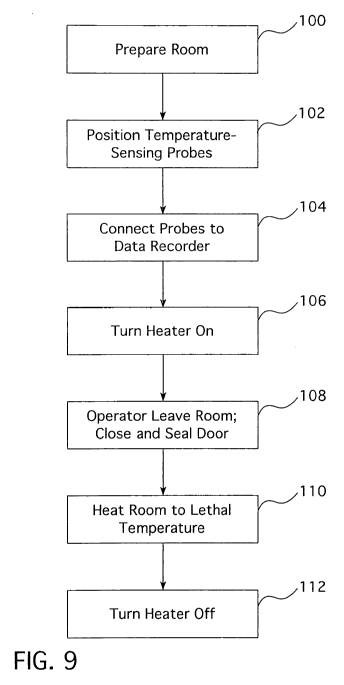
Figure 9 is a flowchart of the process for eradicating bed bugs and other
pests using the
heater 24 according to various embodiments of the present invention. At step
100, the room to be
treated is prepared. As part of the room preparation process, with reference
to Figure 10, furniture
and other large items 120 in the room 122, such as the mattress(es), box
spring(s), appliance(s), etc.,
are moved away from the walls of the room 122, to the extent possible, stacked
and arranged so that
heated air from the heater 24 can flow evenly around, over, and under the
items 120. In addition,
sprinkler heads, if any, in the room may be modified so that they are
deactivated - that is, so that
they do not go off during the heat treatment process. The sprinkler heads may
be modified, for
example, by draining the sprinkler system, removing the sprinkler heads and
putting plugs in their
place, using different sprinkler heads that are not activated at the
temperatures to be used in the
treatment process (e.g., not activated at temperatures below 130 F), and/or
adjusting the sprinkler
heads so that they are not activated at the temperatures to be used in the
treatment process. In
addition, as part of the room preparation process, the smoke detection system
in the room, may be
modified so it is deactivated, such as by removing its power source or turning
it off.
In addition, electronic devices in the room that may be sensitive to high
temperatures, such as
computers, televisions, radio, etc., may be removed or, if left in the room,
disconnected from power.
-8-
CA 02737626 2011-03-18
WO 2010/036331 PCT/US2009/005279
Similarly, the refrigerator (if any) in the room may be unplugged. Also, the
air conditioner (if any)
should be turned off. Indeed, the air conditioner preferably should be turned
off the twelve to
twenty-four hours prior to the heat treatment to reduce the time it will take
to heat the ambient air in
the room to the lethal temperature.
In addition, the window(s) and other openings in the room (except the door at
this point)
should be tightly closed. Preferably, no other external room sealings are
needed. That is, in contrast
to prior heat treatment processes where the treatment area is tented so that
the room is enclosed in a
tent or other sealant, external room sealings do not need to be used according
to various
embodiments of the heat treatment process of the present invention.
In addition, as part of the room preparation process, the heater 24 is placed
in the room.
According to various embodiments, the separate sections 10, 12 of the heater
24 may be transported
separately to the room, and then the two sections 10, 12 may be connected to
form the functional
heater 24 once the two sections 10, 12 are transported to the room. Using two
separate sections 10,
12 obviates the need to carry both sections 10, 12 at once to the room to be
treated, which may be
difficult in situations where the room to be treated is on an upper floor of a
high-rise building.
Multiple heater sections also allows for customization of the heater coil
configurations, as described
above.
At step 102, a number of temperature-sensing probes 124 are placed throughout
the room.
Preferably, at least six temperature-sensing probes 124 are placed throughout
the room 122. For
example, one may be placed at each of the following locations: air intake for
the heater 24 (e.g.,
close to grill 42, see Fig. 6); one or more ambient air locations, preferably
approximately six feet
from the floor; high and low locations into the wall void of the wall
supporting the headboard of the
bed, (as well as other wall, ceiling and floor void spaces); in the mattress;
and inside the core of a
wood member of the room, such as a wooden piece of furniture in the room.
Alternatively, one or
more temperature-sensing probes may be placed in scrap wood of similar
thickness to furniture of
the room to avoid having to drill holes in the furniture for a probe. It
should be noted that the step of
locating the temperature-sensing probes may be performed after preparation of
the room (step 100),
or it may be performed while the room is being prepared.
At step 104, the temperature-sensing probes 124 are communicatively connected
to an
electronic data recorder 126. The data recorder 126 may be include a processor
and a memory, and
may be located inside or preferably outside of the room being treated. The
temperature-sensing
probes 124 may be wired and/or wirelessly connected to the data recorder 126.
The data recorder
126 may receive the temperature readings from the various temperature-sensing
probes 124 and
record the data in its memory along with a timestamp for when the readings
where taken or recorded.
-9-
CA 02737626 2011-03-18
WO 2010/036331 PCT/US2009/005279
According to various embodiments, the data recorder 126 may be an ECR1
Paperless Recorder from
Chromalox, Inc., or any other suitable electronic data recorder. In addition,
numerous monitoring
points, such as fifteen (15) to twenty-five (25) monitoring points, may be
identified throughout the
room and marked with adhesive stickers or other identifiers, which preferably
are numbered to aid in
accurate data collection. As described below, the surface temperatures of
these locations may be
measured with a handheld infrared thermometer from time to time during the
heating process, such
as every hour for the first four hours and every two hours afterward for the
duration of the heat
remediation service according to various embodiments.
At step 106, the heater 24 is turned on. According to various embodiments,
first the fan 16 is
turned on, and then the heating coils 22 of the heater 24. In some instances,
additional ventilation of
the room may be needed. In these circumstances, additional, separate fans
units may be placed
throughout the room. These fan units may be turned on prior to activation of
the heater coils 22. In
addition, if airflow from the heater 24 is directly on walls or furniture, the
heater 24 may be
repositioned or reflective insulation may be used to protect the walls and
furniture. One or more
external generators (not shown) may be used to power components of the heater
24, such as the
motor 16, for example. In addition or alternatively, components of the heater
24 (such as the motor
16 for the heater coils 22) may be electrically powered from conventional wall
outlets, air
conditioning, and/or electrical appliance power outlets in the room, as
described above. In addition,
for example, a generator may be used to power one power circuit (such as the
power circuit for the
fan motor) and wall outlets in the room or otherwise in the building may be
used to power the power
circuits for the heater coils 22.
At step 108, the operator(s) leaves the room 122. The door is preferably
closed and sealed to
retain the hot air inside the room 122.
At step 110, the room is heated to the lethal temperature, which is preferably
in the range of
120 F to 130 F for ambient air and 111 F to 113 F for voids in the walls, etc.
in the treatment area.
The temperature readings from the temperature-sensing probes, collected by the
data recorder, may
be monitored to determine when the room temperature reaches the lethal level.
The temperature
readings may be collected periodically, such as every five minutes to every
two hours, for example,
during the heating process. The heating of the room 122 to the lethal level
may be relatively gradual,
such as over a period of hours, because furniture and cabinets made of
laminated components are
preferably heated slowly over several hours to prevent the laminated surfaces
from expanding faster
than the core and breaking the adhesive bonds.
Throughout the heating process, the temperature readings may be monitored by
the
temperature sensing probes 124, whose temperature data is collected and stored
by the data recorder
-10-
CA 02737626 2011-03-18
WO 2010/036331 PCT/US2009/005279
126. In addition, a human operator may enter the room from time to time during
the heating process
to spot check surface temperatures with, for example, an infrared thermometer
to validate readings
from the temperature-sensing probes 124 (which may be thermocouples), and to
visually inspect the
room for damage and bed bug activity. Preferably, the human operator takes and
records the surface
temperature readings at the pre-identified and pre-marked monitoring points,
described above. Such
human observation may take place every hour for the first four hours of the
heating process, and then
every two hours thereafter.
Once these threshold temperatures are reached, the room is heated for a period
of time (the
treatment time period), such as two hours, three hours, or more. Preferably,
the threshold
temperature is 113 F for all void and interior structural temperatures, and
the preferably treatment
time period is four hours. Accordingly, once all void and interior structural
temperatures have
exceeded the threshold temperature (e.g., 113 F) for the treatment time period
(e.g., four hours), at
step 112, the heater 24 may be turned off. First, the heater coils 22 may be
turned off, but the fan 16,
and any other fan units in the room, preferably should run for a minimum of
ten minutes after the
heater coils 22 are turned off to help dissipate the heat. As even cooling of
the room is important to
prevent damage, the room air conditioner should not be turned on at this
point, but rather preferably
is not turned on until the day following the treatment.
According to various embodiments, once the surface temperatures of the heater
coils 22 drops
below 105 F, the heater 24 and temperature monitoring equipment may be removed
from the room.
Various embodiments of the present invention are also directed to a kit that
can be used to
eradicate bed bugs and other pests through heat. The kit may comprise: (i) the
two sections 10, 12 of
the heater 24; (ii) a number of temperature sensing probes 124; and (iii) the
data recorder 126 (along
with any required software). In addition, the kit may comprise means for
communicatively
connecting the temperature-sensing probes 124 and the data recorder 126. For
example, the kit may
comprise wires if the temperature-sensing probes 124 are wired to the data
recorder 126. If the
temperature-sensing probes 124 wirelessly communicate with the data recorder
126, the data
recorder 126 may comprise an internal or external radio for receiving the
wireless temperature
reading data from the temperature-sensing probes 124. According to additional
embodiments, the kit
may also comprise one or a number of electric generators for powering one of
the power circuits of
the heater 24. In addition, the kit may comprise an infrared thermometer to
measure temperatures in
the room. In addition, the kit may comprise multiple different first (or
heater) sections 10 of the
heater 24 so that the operator has the option of which heater section 10 to
use depending on the
available power sources.
-11-
CA 02737626 2011-03-18
WO 2010/036331 PCT/US2009/005279
While several embodiments of the present invention have been described herein,
it should be
apparent that various modifications, alterations, and adaptations to those
embodiments may occur to
persons skilled in the art. For example, certain steps of Figure 9 may be
performed in different
orders or at the same time. It is therefore intended to cover all such
modifications, alterations, and
adaptations without departing from the scope and spirit of the present
invention as defined by the
appended claims.
-12-