Note: Descriptions are shown in the official language in which they were submitted.
CA 02737798 2011-03-18
WO 2010/037040 PCT/US2009/058634
INDIRECT AND DIRECT METHOD OF SEQUESTERING CONTAMINATES
100011 The present application is a continuation-in-part and claims priority
of U.S.
Patent Application No. 12/459,685 entitled "Gas Liquid Contactor and Effluent
Cleaning
System and Method" filed July 6, 2009, and claims the benefit of U.S.
Provisional
Application No. 61/100,564 entitled "System for Gaseous Pollutant Removal"
filed
September 26, 2008, U.S. Provisional Application No. 61/100,606 entitled
"Liquid-Gas
Contactor System and Method" filed September 26, 2008, and U.S. Provisional
Application No. 61/100,591 entitled "Liquid-Gas Contactor and Effluent
Cleaning
System and Method" filed September 26, 2008; all of which are herein
incorporated by
reference as if set forth in their entireties. In addition, the present
application is related to
the subject matter of U.S. Patent Application No. 12/012,568 entitled "Two
Phase
Reactor," filed February 4, 2008, which is a continuation of U.S. Patent
Application No.
11/057,539 entitled "Two Phase Reactor" filed February 14, 2005, now Patent
No.
7,379,487, both of which applications are herein incorporated by reference as
if set forth
in their entireties.
BACKGROUND OF THE INVENTION
Field of the Invention
100021 The invention generally relates to a method for sequestration
contaminates.
More particularly, the invention relates to significant performance
enhancement over
existing mineral carbonation processes through the use of a high mass transfer
system and
an efficient pH swing reaction, e.g., a direct and indirect method of
sequestering with a
gas liquid contactor.
Discussion of the Related Art
[00031 Fossil fuel combustion, including coal, petroleum and natural gas,
supply more
than two thirds of our nation's electricity and nearly all of our
transportation energy
needs. With our expanding economy and national security needs, our reliance on
fossil
fuels will likely continue for the next two to three decades. Carbon dioxide
has been
identified as a Green House Gas (GHG) and is implicated in anthropogenic
climate
warming. In the U.S., CO2 accounts for nearly 95% of energy related emissions
and 85%
1
CA 02737798 2011-03-18
WO 2010/037040 PCT/US2009/058634
proposed and include reducing GHG source emissions through the use of more
energy
efficient, renewable and alternative fuel systems, and enhancing the economic
viability of
technologies that capture and store or sequester CO2.
[0004] Reduction in the atmospheric concentration of CO2 greenhouse gas can be
achieved by capturing CO2 emissions from large industrial sources and
permanently
storing captured CO2 in some form. For example, permanent storage of captured
CO2 can
be achieved by injecting pressurized CO2 underground or undersea.
Alternatively, CO2
can be converted to calcium carbonate or magnesium carbonate and land filled.
With the
CO2 injection approach the risks exist that CO2 will escape from the storage
site. To
mitigate these risks the CO2 storage sites have to be monitored and the
resources have to
be committed in case a CO2 leak occurs. If the CO2 is converted to solid
carbonates, the
risks associated with permanent storage are essentially zero, making this
approach to
permanent CO2 storage more attractive over the underground CO2 storage
approach.
[0005] Carbon dioxide sequestration is attractive for GHG reduction because it
enables
the continued use of fossil fuels including coal, petroleum and natural gas,
which supply
more than two thirds of our nation's electricity and nearly all of our
transportation energy
needs. With our expanding economy and national security needs, our reliance on
fossil
fuels will likely continue for the next two to three decades.
[0006] The mineral carbonation process is an attractive storage option for CO2
as it
offers many advantages over other sequestration approaches. Primarily these
are the
formation of geologically stable and environmentally benign carbonates which
present
minimal safety and legacy issues. However, most mineral carbonation processes
have
been assessed to be uneconomical due to slow dissolution kinetics and
unfavorable
carbonation energetics. Huijgen, et al., Cost evaluation of C02 sequestration
by
aqueous mineral carbonation, Energy Conversion and Management, 48, pp. 1923-
1935
(2007), which is hereby incorporated by reference as if fully set forth
herein.
SUMMARY OF THE INVENTION
[0007] Accordingly, the invention is directed to an indirect and direct method
for
sequestering contaminates. More particularly, the invention relates to
significant
performance enhancement over existing mineral carbonation processes through
the use of
a high mass transfer system and an efficient pH swing reaction that obviates
one or more
of the problems due to limitations and disadvantages of the related art.
2
CA 02737798 2011-03-18
WO 2010/037040 PCT/US2009/058634
[00081 An advantage of the invention is to provide a high mass transfer system
having
high liquid surface refreshment/renewal rates at a gas liquid interface.
[00091 Another advantage of the invention is to provide efficient indirect
mineral
carbonation process which uses a weak base and a strong acid solvent. The weak
base
promotes carbon dioxide absorption and the strong acid promotes mineral
dissolution.
[00101 Yet another advantage of the invention is to provide efficient mineral
carbonation process which using phase separation of a solvent.
[00111 Additional features and advantages of the invention will be set forth
in the
description which follows, and in part will be apparent from the description,
or may be
learned by practice of the invention. The objectives and other advantages of
the invention
will be realized and attained by the structure particularly pointed out in the
written
description and claims hereof as well as the appended drawings.
[00121 An embodiment of the invention is directed towards a method of
sequestering
gas phase molecules. The method includes forming a plurality of essentially
planar liquid
jets, each of said liquid jets including a substantially planar sheet of an
aqueous slurry
solution, and the plurality of liquid jets arranged in substantially parallel
planes. A gas is
provided with gas phase molecules to a gas liquid contactor. The method also
includes
mineralizing at least a portion of the gas phase molecules by a mass transfer
interaction
between the gas phase molecules and an aqueous slurry within the gas liquid
contactor.
[00131 Yet another embodiment of the invention is directed towards a method of
sequestering gas phase molecules. In this embodiment, a plurality of
essentially planar
liquid jets are formed with a gas liquid contactor. The essentially each of
the essentially
planar liquid jets include a substantially planar sheet of an aqueous slurry
solution, said
plurality of liquid jets arranged in substantially parallel planes. A gas is
provided to the
gas liquid contactor with gas phase molecules and the gas phase molecules are
reacted by
a mass transfer interaction between the gas phase molecules and an aqueous
solution to
form a reacted composition. The method also includes reacting at least a
portion of the
composition to form carbonates in a reactor. Also, the method includes
recycling at least
a portion of the aqueous composition such that it is reefed into the gas
liquid contactor for
forming the reacted composition.
[00141 Still yet another embodiment of the invention is directed towards
direct
sequestering carbon dioxide gas phase molecules from a flue gas of a coal
fired plant.
The method includes forming a plurality of essentially planar liquid jets with
a gas liquid
3
CA 02737798 2011-03-18
WO 2010/037040 PCT/US2009/058634
contactor. Each of the liquid jets includes a planar sheet of an aqueous
slurry solution,
and the plurality of liquid jets are arranged in substantially parallel
planes. In this
embodiment, the aqueous slurry solution includes at least one of Ca(OH)2 and
Mg(OH)2
in a range of about 5% (w/w) to about 10 %(w/w). Flue gas with the carbon
dioxide gas
phase molecules is provided to the gas liquid contactor. Carbon dioxide is
mineralized
by a mass transfer interaction between the carbon dioxide gas molecules and
the aqueous
slurry solution.
[00151 It is to be understood that both the foregoing general description and
the
following detailed description are exemplary and explanatory and are intended
to provide
further explanation of the invention as claimed.
BRIEF DESCRIPTION OF THE DRAWINGS
[00161 The accompanying drawings, which are included to provide a further
understanding of the invention and are incorporated in and constitute a part
of this
specification, illustrate embodiments of the invention and, together with the
description,
serve to explain the principles of the invention.
[00171 In the drawings:
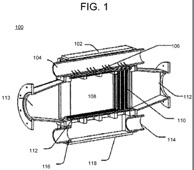
[00181 FIG. 1 illustrates a block diagram of a system for producing a flat jet
according
to an embodiment of the invention;
[00191 FIG. 2 illustrates a direct sequestering process according to another
embodiment of the invention;
[00201 FIG. 3 illustrates an indirect sequestering process according to
another
embodiment of the invention;
[00211 FIG. 4 illustrates a sequestering process according to another
embodiment of
the invention;
[00221 FIG. 5A illustrates an exploded perspective view of a nozzle apparatus
used in
Example 1;
[00231 FIG. 5B illustrates a bottom perspective view of a plenum used in
Example 1;
[00241 FIG. 5C illustrates a top perspective view of a plenum used in Example
1;
[00251 FIG. 5D illustrates an exit side perspective view of a nozzle plate
used in
Example 1;
[00261 FIG. 5E illustrates an entrance side perspective view of a nozzle plate
used in
Example 1;
4
CA 02737798 2011-03-18
WO 2010/037040 PCT/US2009/058634
100271 FIG. 5F illustrates a perspective view of a fluid condition used in
Example 1;
100281 FIG. 6 is a graph of -ln(n/no) versus residence time according to
Example 1;
100291 FIG. 7 is a graph of -ln(n/no) versus residence time according to
Example 2;
100301 FIG. 8 is a graph of -ln(n/no) versus residence time according to
Example 3;
100311 FIG. 9 is a graph of -ln(n/no) versus residence time according to
Example 4;
100321 FIG. 10 is a graph of -ln(n/no) versus residence time according to
Example 5; and
100331 FIG. 11 is a graph of -ln(n/no) versus residence time according to
Example 6.
DETAILED DESCRIPTION OF THE ILLUSTRATED EMBODIMENTS
100341 Embodiments of the invention generally relate to a method for
sequestering
carbon dioxide for a combustion process, e.g., a coal fired plant. In
particular, the
invention relates to significant performance enhancement over existing mineral
carbonation processes through the use of a high mass transfer system and an
efficient pH
swing reaction.
100351 Embodiments are directed towards an innovative carbon capture and
sequestration system which solves technical, energy and economic feasibility
issues of
CO2 mineral carbonation and provides for beneficial use of sequestered CO2. In
embodiments of the invention a high performance mass transfer system as
described in
U.S. Patent Application No. 12/459,685, entitled "Gas Liquid Contactor and
Effluent
Cleaning System and Method," filed on July 6, 2009, which is hereby
incorporated by
reference as if fully set forth herein, is used. This gas liquid contactor is
about thirty
times less in size and costs about sixty percent less than conventional
capture systems
with the new mineral carbonation system.
100361 One embodiment of the invention is directed towards a direct
sequestering
process flow. The direct sequestering process flow allows for sequestration of
carbon
dioxide in one step, e.g., forming calcium or magnesium carbonate by
contacting aqueous
slurries of alkaline materials with the flue gas containing CO2 with a gas
liquid contactor.
100371 Another embodiment of the invention is directed towards a method of
sequestering gas phase including forming a plurality of essentially planar
liquid jets, each
of said liquid jets including a planar sheet of an aqueous slurry solution,
the plurality of
liquid jets arranged in substantially parallel planes. Gas phase molecules may
be
provided and at least a portion of the gas phase molecules may be mineralized
by a mass
transfer interaction between the gas phase molecules and the aqueous slurry.
CA 02737798 2011-03-18
WO 2010/037040 PCT/US2009/058634
[00381 The sequestering takes place in a gas liquid contactor. The gas liquid
contactor
is described with reference to U.S. Patent Application No. 12/459,685,
entitled "Gas
Liquid Contactor and Effluent Cleaning System and Method," filed on July 6,
2009,
which is hereby incorporated by reference as if fully set forth herein, is
used. In
embodiments of the invention gas phase molecules include combustion gases,
flue gas,
carbon dioxide and combinations thereof. In a preferred embodiment, the gas
phase
molecules include carbon dioxide to be sequestered.
[00391 In embodiments of the invention, the aqueous slurry may include a solid
material and water. The solid material includes an alkaline material such as
silicates
and/or industrial waste alkaline material. The silicates may be
calcium/magnesium
silicates, e.g., olivine, wollastonite, and serpentine silicates and
combinations thereof.
The industrial waste alkaline material may include at least one of steel slag,
cement kiln
dust, fly ash, and combinations thereof. In a preferred embodiment, the
aqueous solution
includes about 5% (w/w) to about 10% (w/w) Ca(OH)2. The solids may be in a
range
from about I% (w/w) to about 20% (w/w).
[00401 In a preferred embodiment, the aqueous solution also includes a
promoter for
CO2 absorption such as an amine. The amine may include monoethanol amine, 1,4-
piperazinediethanol, piperazine, hydroxyethylpiperazine and other amines that
have a
rapid reaction with carbon dioxide as known in the art.
[00411 In a preferred embodiment, the aqueous solution may include a corrosion
inhibiter and an antifoaming agent. The corrosion inhibiter may include sodium
metavanadate (NaVO3) and copper carbonate (CUCO3). The antifoaming agent may
include a silicon compound based defoamer including polydimethylsiloxane,
hydrophobic
silica, silicone glycols and other silicone fluids.
[00421 In an embodiment of the invention the gas liquid contactor may also
include a
plurality of operating modules as described with reference to U.S. Patent
Application No.
12/459,685, entitled "Gas Liquid Contactor and Effluent Cleaning System and
Method,"
filed on July 6, 2009, which is hereby incorporated by reference as if fully
set forth herein.
[00431 The method when forming an array of uniformly spaced flat liquid jets
step
includes forming the flat liquid jets at a liquid plenum pressure in a range
from about 2
psig to about 25 psig. The flat liquid jets include at least one of the flat
liquid jets in the
array with a width greater than about 1 cm. At least one of the flat liquid
jets in the array
includes a width in a range from about 5 cm to about 15 cm, a thickness in a
range from
6
CA 02737798 2011-03-18
WO 2010/037040 PCT/US2009/058634
about 10 m to about 250 m, a length in a range from about 5 cm to about 30
cm, and at
least one of the flat liquid jets in the array has a velocity less than 15
m/sec.
[00441 In a preferred embodiment, direct carbonation under mild conditions is
the
preferred way of converting CO2 into solid carbonates. The overall carbonation
reactions
are:
Ca(OH)2 + CO2 4 CaCO3 + H2O R1
Mg(OH)2 + CO2 4 MgCO3 + H2O R2
[00451 Aqueous slurries containing magnesium hydroxide or steel slag solids
are
contacted with the flue gas using a gas liquid contactor as described with
reference to
U.S. Patent Application No. 12/459,685, entitled "Gas Liquid Contactor and
Effluent
Cleaning System and Method," filed on July 6, 2009, which is hereby
incorporated by
reference as if fully set forth herein. In this embodiment, the direct
carbonation of the
contactor offers two distinctive advantages. The first advantage is the
constant agitation
of the liquid which promotes the dissolution rates of solids. The second
advantage is the
high surface refreshment/renewal rate which increases the rate of CO2 capture.
[00461 Carbonation proceeds in three steps, with the first step being the
dissolution of
the solids:
Mg(OH)2 4 Mg2+ + 20H- R3
In this embodiment, magnesium hydroxide is substantially dissolved. After the
hydroxide
ions are created by dissolution, these ions react with the CO2 captured from
the flue gas:
C02 + 0H' 4 HC03- R4
After the CO2 is converted to the bicarbonate ion and then to the carbonate
ion, the
carbonate ion is reacted with a metal ion to form solid carbonate, for example
as shown in
the following reaction:
Mg 2+ + C032- 4 MgCO3 R5
There are more reactions and species involved in the carbonation process than
represented
by R3-R5, but to keep the discussion simple those additional reactions and
species are not
included. As was mentioned above, the gas liquid contactor of this invention
improves the
rates of R3 and R4 processes.
[00471 In one embodiment, the rate of the dissolution process (R3) can be
defined as:
d [Mg(OH)2 ]
dt kdssor;ds = -kd [Mg(OH)z] Eq. 1
7
CA 02737798 2011-03-18
WO 2010/037040 PCT/US2009/058634
The rate of dissolution is proportional to the total surface area of the
solids, Ssor1d5. The
rate constant ksd has units of mol Since the total surface area of solids,
Ssot,ds, is
s=cmz
proportional to the solids weight in the slurry, another dissolution rate
constant, kd, may
be used. This dissolution rate constant has units of 1 . Therefore, the rate
of the CO2
S
capture process can be defined as:
d[C02] _ _kS[COZ ] Eq. 2
dt
where k is the mass transfer coefficient, S is the interfacial surface area
and [CO2 is the
average CO2 driving force. For a given percent of CO2 removal from the flue
gas the
average CO2 concentration in the reactor is proportional to the inlet CO2
concentration.
The mass transfer coefficient, k, depends on the hydroxide concentration. The
mass
transfer coefficient does not change significantly in the 9 < pH < 13 range.
[0048] Assuming that R5 is not a rate limiting step at steady state, the
dissolution rate
is equal to the CO2 capture rate. Steady state conditions can be verified by
looking at the
pH meter reading. When the steady state conditions are achieved, the pH stays
constant.
The dissolution rate is proportional to the weight percent of the magnesium
hydroxide in
the slurry. The CO2 capture rate is proportional to the CO2 concentration at
the reactor
inlet. By adjusting the weight percent of solids in slurry and varying the CO2
concentration at the inlet, the steady state conditions can be achieved and
the dissolution
rate of the magnesium hydroxide solids may be measured experimentally.
[0049] Six direct sequestration Examples were conducted and the details and
results
are shown in Table 1. The Example details are shown below, Examples 1-6. The
statistical error on the mass transfer coefficients is less than about 20%.
The systematic
error on the mass transfer coefficient is mostly due to the uncertainty in the
specific
surface area of the contactor.
Example Description CO2 Mass Observation
Number Concentr Transfer
Coefficient
cm/s
1 0.1M KOH 3% .09 Baseline test
solution
2 KOH solution 3% .08 Added 0.1 M KOH to
at pH 11.8 keep pH constant
3 1 % Mg(OH)2 3% .07 Added I% Mg(OH)2 to
keep pH constant
8
CA 02737798 2011-03-18
WO 2010/037040 PCT/US2009/058634
4 5% Mg(OH)2 3% .10 pH held constant
throughout example
1% Steel Slag 3% .09 pH held constant
throughout example
6 5% Steel Slag 3% .12 pH held constant
throughout example
100501 One parameter of the dissolution of the alkaline solids is the rate
limiting step.
In the Examples, only when CO2 concentration is dropped to 3% and the
magnesium
hydroxide weight percent is increased to 5% is the parity between the
dissolution rate and
the CO2 capture rate achieved. The dissolution rate for steel slag is
comparable to the
dissolution rate of the magnesium hydroxide, even though steel slag contains a
significant
amount of inert silica which slows the dissolution. The fact that dissolution
rates for slag
and magnesium hydroxide are comparable may be related to the fact that the
solubility
product constant for magnesium hydroxide is much smaller than that for calcium
hydroxide.
100511 Another embodiment of the invention is directed towards a method of
sequestering gas phase. The method includes forming a plurality of essentially
planar
liquid jets in a gas liquid contactor. Each of the liquid jets includes a
planar sheet of an
aqueous solution with the plurality of liquid jets arranged in substantially
parallel planes.
In this method, a gas is provided with gas phase molecules, and the gas phase
molecules
are reacted by a mass transfer interaction between the gas phase molecules and
an
aqueous solution to form a reacted composition.
100521 The aqueous solution includes piperazine and acid, e.g., piperazine and
hydrochloric acid. In a preferred embodiment, the molar ratio of hydrochloric
acid to
piperazine is in a range from about 0.5 to 2. The next step of this method
includes
reacting in a continuous process reactor with silicates to form the
carbonates. The
mineralizing includes reacting the reacted material and an alkaline material
to form
carbonate and mineralizing at least a portion of the reacted composition to
form
carbonates in a reactor. In another step, at least a portion of aqueous
solution is reclaimed
and recycled into the gas liquid contactor.
100531 In a preferred embodiment, the continuous reactor is a continuously
stirred tank
reactor. The thermodynamically favorable mineral carbonation process uses an
amine
(e.g., piperazine dihydrochloride, HN(CH2)4NH=2HC1 or Pz=2HC1) as described by
reactions (6) and (7):
9
CA 02737798 2011-03-18
WO 2010/037040 PCT/US2009/058634
2Pz=2HC1 + CaO=SiO2(s) -) CaC12 + SiO2(s) + H2O + 2 Pz=HCl R6
2Pz=HCl + CO2 + CaC12 + H2O -)CaCO3 (s) + 2Pz=2HC1 R7
In this embodiment, the alkalinity extraction reaction (R6) proceeds as
written because
the singly protonated piperazine product is a thermodynamically favored
species for the
pH conditions of this step. The carbonation reaction (R7) proceeds as written
because the
doubly protonated piperazine product is a thermodynamically favored species
for the pH
conditions of this step. Overall, the reaction of silicate conversion to
carbonate is
exothermic with AH=-87 kJ/mol and AG=-44 kJ/mol. One significant advantage of
the
carbonation chemistry based on using the PZ is that SOx (or NOx) will not have
to be
separately removed. Through analysis and Examples it has been demonstrated
that
significant improvements to the capture and sequestration process is energy
efficient and
cost effective.
[0054] Reference will now be made in detail to an embodiment of the present
invention, an example of which is illustrated in the accompanying drawings.
[0055] FIG. 1 illustrates a block diagram of a system for producing a flat jet
according
to an embodiment of the invention.
[0056] Referring to FIG. 1, a gas liquid contactor is generally depicted as
reference
number 100. This gas liquid contactor is used in embodiments of the invention
for direct
and indirect mineralization processes. The gas liquid contactor includes a
liquid inlet and
a gas inlet. The gas liquid contactor is generally depicted as reference
number 100. In
this embodiment, a cross flow configuration is utilized, the gas flows from
left to right
through the contactor 100. Liquid enters the top 102 of the contactor 100
through inlet
plenum 104 and is forced through the nozzle plates 106 at the top of the
contact chamber
108. In this embodiment, a stability unit is coupled to the nozzle plate and
configured to
reduce instability of jets formed from the gas liquid contactor.
[0057] Substantially stable flat liquid jets are formed by the nozzles and
flow down
through the chamber. The gas flows from left to right in the system depicted
in FIG. 1
between the parallel jets, where the mass transfer takes place, then through
the low
pressure drop mist eliminator 110, and on to the exit 112 from the entrance
113. The
liquid is collected through an anti-splash grid 112 at the bottom of the
contactor, treated
as necessary, and possibly recycled. The anti-splash grid submodule 112 is a
grid with
apertures shaped to receive the flat jets. The anti-splash guard or gas fluid
separator is
also configured to substantially minimize back-splash of liquid in operation.
The
CA 02737798 2011-03-18
WO 2010/037040 PCT/US2009/058634
apertures of the anti-splash grid 112 may be angled slightly towards the exits
114 and/or
116 of the liquid capture outlet plenum 118 to aid in the exit of the fluid
without the
application of pressure to the fluid. The apparatus may include various
modules and
nozzles and are described with reference to U.S. Patent Application No.
12/459,685,
entitled "Gas Liquid Contactor and Effluent Cleaning System and Method," filed
on July
6, 2009, which is hereby incorporated by reference as if fully set forth
herein.
[00581 FIG. 2 illustrates a direct sequestering process according to another
embodiment of the invention.
[00591 In this embodiment, the direct sequestering process is described with
reference
to three Sections. Section 1 includes a gas liquid contactor 202, a gas inlet
204, a fluid
inlet 206, a fluid outlet 208 and gas outlet 210. The gas liquid contactor 202
is operated
at conditions for forming carbonates, e.g., calcium or magnesium carbonate by
contacting
aqueous slurries in the inlet 206 containing alkaline materials with the flue
gas from the
gas inlet 204 with the gas liquid contactor 202. The flue gas may be from a
coal power
plant or other industrial process and includes contaminants to sequester. In
this
embodiment, carbon dioxide is included in the flue gas and is mineralized as
described
herein in a direct process, e.g., one step process with the gas liquid
contactor 202.
[00601 In this embodiment, the alkaline materials may include magnesium
hydroxide,
calcium hydroxide, steel slag, cement kiln dust, fly ash, and a combination
thereof The
alkaline solids may be prepared by grinding the raw alkaline materials until
the particle
size is sufficiently small to provide good conversion to carbonates.
[00611 Section 2 includes an apparatus for making the raw alkaline materials
to be
suitable for the mineral carbonation process. The raw material stream 212
enters the
grinding system 214 including a grinding apparatus as known in the art. The
raw material
may include alkaline materials such as magnesium hydroxide, calcium hydroxide,
wollastonite, steel slag, cement kiln dust, and the like. Before grinding, the
raw material
may have to be crushed to make it acceptable for the grinding system. The
ground material
enters the size sorting system 216 via the stream 218. The size sorting system
can be a
cyclone or any other system capable of separating the ground solids by size as
known in the
art. Smaller size solids (mesh size 200 or smaller) are sent to the additional
pretreatment
step 218 via the stream 220. The larger size solids are sent back to the
grinding system 214
via the stream 222. The additional pretreatment step 218 may involve magnetic
separation,
11
CA 02737798 2011-03-18
WO 2010/037040 PCT/US2009/058634
heating of solids or any other steps which may increase the dissolution rate
of the alkaline
materials. The ground alkaline solids are sent to a mixer 224.
[00621 Section 3 includes a solid separation system 228 that has an input 208
which is
the fluid outlet 208 of the gas liquid contactor 202 and an outlet 230
including solid
reaction products and a liquid stream 232 sent to the mixer 224.
[00631 The solid separation system 228 includes a dewatering system such as a
belt
filter or a filter press and a system to concentrate solid to on optimal level
for operation of
the dewatering system. The system for concentration of solids may be a gravity
based
system such as a thickener or settling tank. Alternatively, the system for
concentration of
solids may be a hydrocyclone.
[00641 The mixer 224 mixes the liquid from the liquid stream 232 and alkaline
solids
to form a desired aqueous slurry that is output in stream 206. Alternatively,
the liquid
stream 232 and solid stream 226 can be mixed in the capture system 202.
[00651 FIG. 3 illustrates an indirect sequestering process according to
another
embodiment of the invention. In this embodiment, the indirect sequestering
process is
described with reference to three Sections. Section 1 includes a gas liquid
contactor 302,
a gas inlet 304, a fluid inlet 310, a fluid outlet 308 and gas outlet 306. The
gas liquid
contactor 302 is operated at conditions for reacting a flue gas, e.g.,
containing carbon
dioxide, to form a reacted molecule that captures carbon dioxide. The flue gas
may be
from a coal power plant or other industrial process and include contaminants
to sequester.
In this embodiment, the fluid inlet 310 includes piperazine dihydrocholoride
[00661 Section 2 includes an apparatus for making the raw alkaline materials
to be
suitable for the mineral carbonation process. The raw material stream 312
enters the
grinding system 314 including a grinding apparatus as known in the art. The
raw material
may include calcium and magnesium silicates, as well as steel slag and/or
other alkaline
materials. Before grinding, the raw material may have to be crushed to make it
acceptable for the grinding system. The ground material enters the size
sorting system
316 via the stream 318. The size sorting system 316 can be a cyclone or any
other system
capable of separating the ground solids by size as known in the art. Smaller
size solids
(mesh size 200 or smaller) are sent to the additional pretreatment step 318
via the stream
320. The larger size solids are sent back to the grinding system 314 via the
stream 322.
The additional pretreatment step 318 may involve magnetic separation, heating
of solids
12
CA 02737798 2011-03-18
WO 2010/037040 PCT/US2009/058634
or any other steps which may increase the dissolution rate of the alkaline
materials. The
ground alkaline solids are sent to Section 3 via the stream 326.
10067] Section 3 includes a batch reactor 324 for forming carbonates and the
recycling
of piperazine which is sent back to the gas liquid contactor 302 via stream
310. The batch
reactor also receives alkaline solids via stream 316. In this embodiment, the
alkaline
materials may include magnesium hydroxide, calcium hydroxide, steel slag,
cement kiln
dust, fly ash, and combination thereof.
10068] In a continuous reactor the thermodynamically favorable mineral
carbonation
process using an amine (e.g., piperazine dihydrochloride, HN(CH2)4NH^2HC1 or
Pz^2HC1) is described by reactions (8) and (9):
2Pz.'2HC1 + CaO.Si02(s) - CaC12 + Si02(s) + H2O + 2 Pz-HCI R8
2Pz.'HCI + CO2 + CaC12 + H2O -CaCO3 (s) + 2Pz.'2HC1 R9
10069] In this embodiment, the alkalinity extraction reaction (R8) proceeds as
written
because the singly protonated piperazine product is a thermodynamically
favored species
for the pH conditions of this step. The carbonation reaction (R9) proceeds as
written
because the doubly protonated piperazine product is a thermodynamically
favored species
for the pH conditions of this step. Overall, the reaction of silicate
conversion to carbonate
is exothermic with OH=-87 kJ/mol and AG=-44 kJ/mol. One significant advantage
of the
carbonation chemistry based on using the PZ is that SOx (or NOx) will not have
to be
separately removed. Through analysis and Examples it has been demonstrated
that
significant improvements to the capture and sequestration process is energy
efficient and
cost effective.
10070] In a preferred embodiment, piperazine is used due to its thermodynamic
properties of piperazine. For example, the high mass transfer coefficients and
high CO2
capacity allows for a reduced size of the gas liquid contactor 302 as compared
to a direct
process. In addition, the operation with piperazine results in a reduced
solvent slip and
thefore excellent thermal stability and solvent makeup cost. There are also
rapid mineral
dissolution kinetics. In addition, aqueous solutions containing piperazine can
be
separated into the piperazine rich and salt rich phases. The phase separation
properties of
piperazine containing solutions may also be used to conduct calcite
precipitation in a
controlled manner therefore improving the process robustness. Other amines or
a
mixture of amines may also be used for the mineral carbonation process.
13
CA 02737798 2011-03-18
WO 2010/037040 PCT/US2009/058634
[00711 Finally, as solvent makeup cost is an important aspect to any system
this
parameter should be considered. Because of the low vapor pressure the
piperazine loss
due to entrainment in the flue gas is minimal and also losses due to the
piperazine coming
out with the solids is minimal as well. That is, piperazine may be readily
recycled.
[00721 FIG. 4 illustrates a sequestering process according to another
embodiment of
the invention.
[00731 FIG. 4 is a process flow for mineral carbonation process for removing
carbon
dioxide from combustion gas stream, e.g., from a coal fired plant. Referring
to FIG. 4,
the process flow includes ten sections.
[00741 Section 1 is an optional flue gas conditioning system. Referring to
Section 1, it
includes an inlet 402 of flue gas into an optional heat exchanger/chiller 404
and an outlet
406. The flue gas conditioning system receives an inlet gas which may have
already seen
some processing, e.g., processing to remove acid gases such as SO2, HCI, and
the like.
The heat exchanger/chiller 404 is optional as it depends on the inlet gas
constituents and
absorber chemistry as known in the art, e.g., ammonia/ammonia carbonate would
require
a chiller. The flue gas has been cooled and scrubbed of SO2, e.g., from a
contactor
system (not shown) according to an embodiment of the invention. In this
embodiment,
the flue gas 402 contains contaminates such as C02, N2, H2O, 02 and other
trace gases.
[00751 The flue gas flows through the gas conditioning system (Section 1) into
the CO2
scrubber (Section 2) where a significant fraction of the CO2 is removed from
the stream
by contacting with the solvent.
[00761 Section 2 is a CO2 absorber loop. Referring to Section 2, the absorber
loop
includes gas liquid contactor 408 and a catch tank 410. The gas liquid
contactor is a gas
liquid contactor as described in U.S. Patent Application No. 12/459,685,
entitled "Gas
Liquid Contactor and Effluent Cleaning System and Method," filed on July 6,
2009,
which is hereby incorporated by reference as if fully set forth herein. A heat
exchanger/chiller 412 of Section 5 is an optional component. Again, the heat
exchanger/chiller 410 is optional as it depends on the inlet gas constituents
and absorber
chemistry as would be known to one of skill in the art. In this embodiment,
the gas
liquid contactor is coupled to an outlet 406 of the Section 1. The gas liquid
contactor 408
is coupled to a catch tank 410 and to a heat exchanger/chiller 412 (Section 5)
as part of
recycle loop.
14
CA 02737798 2011-03-18
WO 2010/037040 PCT/US2009/058634
[0077] In operation, the flue gas containing CO2 is directed through an inlet
414 of the
gas liquid contactor 408 and stripped of a portion of the CO2. The CO2
absorber loop of
Section 2 includes various values and pumps as required for appropriate flow
and recycle
of the liquid and operation as known in the art. After contacting the gas in
the contactor
408, the absorber solution now carries an additional amount of CO2 to catch
tank 410 as
part of the recirculation loop.
[0078] In this embodiment, the energy requirements of the CO2 absorber loop
are
handled by the heat exchanger/chiller 412 of Section 5. The general chemistry
described
here, using ammonium carbonate, amines, or alkanolamines, absorbs CO2 more
preferably when chilled below the flue gas temperatures seen in typical
systems.
Therefore, if required, the Section 5 heat exchanger/chiller 412 provides that
cooling
capacity to maintain optimal operating conditions of the absorber solution.
[0079] Section 3 is a CO2 stripper loop. Section 3 includes an inlet 416
coupled to a
heat exchanger/chiller 418 having an outlet 420 and 422. The outlet 422 is
coupled to a
gas liquid contactor 408 via a recycle loop.
[0080] Section 4 is an ammonia or amine absorber loop. Section 4 is designed
to
capture the ammonia or amine slip in the flue gas after it leaves the CO2
absorber 408.
This may be a particular issue with NH3, depending on the temperature of the
absorber
solution (colder leads to less slip). This loop includes a gas liquid
contactor 426 coupled
to the inlet 424. Again, the gas liquid contactor is described in U.S. Patent
Application
No. 12/459,685, entitled "Gas Liquid Contactor and Effluent Cleaning System
and
Method," filed on July 6, 2009, which is hereby incorporated by reference as
if fully set
forth herein.
[0081] The gas liquid contactor 426 includes an outlet 428 coupled to catch
tank 430,
recycle loop, and an outlet 432. If an amine, such as piperazine or
alkanolamines, are
used as the absorber solution, there is less need for Section 4, thus
implementation of
such a section would be determined through examination of the overall process
requirements and temperatures. This Section 4 is optional as smaller molecular
weight
amines may slip and it may be advantageous to capture while higher molecular
weight
amines may not slip and therefore, they may not need to be processed. The
output 432
may be directed to a flue gas stack 434 which has an output 436.
[0082] Section 6 describes precipitation of mineral carbonate in the
precipitation
reactor 438. The precipitation reactor 438 is a continuous stir tank reactor
as known in
CA 02737798 2011-03-18
WO 2010/037040 PCT/US2009/058634
the art. In this reactor 438, the stream 420 rich in the carbonate ion, is
mixed with the
stream 456 rich in the calcium ion. With sufficient residence time, the
precipitation
reactor calcium carbonate forms and the liquid stream 440 containing
precipitated
calcium carbonate is sent to the separation system 442.
[0083] Section 7 describes separation of solids from the liquid stream in the
separation
system 442. The separation can be accomplished by a number of methods
including belt
filter and filter press. In particular, the separation system can include a
belt filter for
continuous operation. The separation system 442 may include methods for
providing the
optimum concentration of solids to the belt filter or filter press. These
methods may
include thickener tanks or some other type of gravity settling methods.
Alternatively or
in conjunction with gravity, settling hydrocyclones can be used to provide the
optimum
concentration of solids to the belt filter or filter press. The separation
system 442 may
also include methods for washing solids in order to decrease amine losses. The
solid
stream 444 containing mostly solid calcium carbonate with the residual water
is either
land filled or used for making of the cement. The liquid stream 446 is sent to
the
alkalinity extractor 450. The alkalinity extractor 450 is a continuous stir
tank reactor as
known in the art.
[0084] Section 8 describes extraction of alkalinity from the alkaline mineral
such as
wollastonite or from alkaline industrial byproducts such as steel slag, cement
kiln dust,
etc. In the alkalinity extraction reactor 450 the liquid stream 446 and the
solid stream 474
are mixed. The alkalinity extraction reactor includes a mixer and a heater.
The mixer and
the heater aid in speeding up the rate of the dissolution. The dissolved
alkalinity is
carried by a stream 452 and the stream 448 contains inert solids such as
silica and
undissolved materials. Stream 452 is sent to the phase separator 454 where the
calcium
chloride is separated from amine. The calcium chloride stream 456 is sent to
the
precipitation reactor 438 and the amine stream is sent to CO2 absorber via the
stream 458.
[0085] Section 9 describes separation of the stream 452 into the calcium rich
and
amine rich streams. This may be accomplished for piperazine as described in
Cullinane,
Thermodynamics and Kinetics ofAqueous Piperazine with Potassium Carbonate for
Carbon Dioxide Absorption, pp. 167-171, Dissertation, The University of Texas
at
Austin, (2005), which is hereby incorporated by reference as if fully set
forth herein. In
the alkalinity extraction step, the pH of the liquid increases making
piperazine less
soluble. The subsequent temperature decrease will cause the piperazine to
precipitate
16
CA 02737798 2011-03-18
WO 2010/037040 PCT/US2009/058634
from the liquid or separate as a liquid phase. Therefore, the phase separation
system
should include means for decreasing the temperature of the liquid and for the
physical
separation of piperazine rich and salt rich phases. The temperature of the
liquid can be
decreased using a heat exchanger. Potentially, the heat exchanger used for
phase
separation can be combined with the heat exchanger 418. Physical separation of
the
piperazine rich and salt rich phases can be accomplished by standard methods.
If
piperazine precipitates as a solid piperazine hexahydrate, then a system
similar to the one
described in Section 7 can be used as a mechanical device to accomplish phase
separation. Subsequently, the piperazine can be redissolved and sent via the
stream 458
to the CO2 capture system. If piperazine separates as a liquid phase, the
piperazine rich
and salt rich phases can be separated by standard methods. Specifically,
methods used for
separation of organic from aqueous phases can be used. More specifically,
systems for
separation of oil from water can be used as a mechanical device to accomplish
phase
separation.
[00861 Section 10 describes the methods for making the raw alkaline materials
to be
suitable for the mineral carbonation process. The raw material stream 460
enters the
grinding system 462 including a grinding apparatus as known in the art. Before
grinding,
the raw material may have to be crushed to make it acceptable for the grinding
system.
The ground material enters the size sorting system 468 via the stream 464. The
size
sorting system can be a cyclone or any other system capable of separating the
ground
solids by size. The smaller size solids (mesh size 200 or smaller) are sent to
the
additional pretreatment step 472 via the stream 470. The larger size solids
are sent back
to the grinding system 462 via the stream 466. The additional pretreatment
step 472 may
involve magnetic separation, heating of solids or any other steps which may
increase the
dissolution rate of the alkaline materials.
[00871 The operation of the system is in FIG. 4 now described. This system is
used for
mineral carbonation of CO2 and other constituents in the flue gas to form
calcium
carbonates by reaction with calcium containing alkaline materials. In this
embodiment,
the overall reaction is described by the following reaction:
CaSiO3 + CO2 - CaCO3 + Si02
[00881 In this embodiment, carbon dioxide CO2 enters the mineralization
process via
the stream 402. The alkaline material enters the process via the stream 460.
The calcium
carbonate product exits the system through the stream 444. The precipitated
calcium
17
CA 02737798 2011-03-18
WO 2010/037040 PCT/US2009/058634
carbonate product is of sufficient quality to use in limestone flue gas
desulfurization
systems or other applications such as paint additives as known in the art. The
silica and
unreacted alkaline feed material exits the mineralization process via the
stream 448.
[00891 The flue gas flows through the gas conditioning system (Section 1) into
the CO2
scrubber (Section 2) where a significant fraction of the CO2 is removed from
the stream
by contacting with a solvent, e.g., piperazine hydrochloride. The flue gas
exiting the CO2
scrubber is sent through the optional scrubber (Section 4) to strip any amine
vapors
entrained into the flue gas during the CO2 scrubbing process. Depending on the
stack
requirements additional flue gas conditioning steps may be required, which
take place in
block 434.
[00901 The solvent flow loop includes streams 416, 420, 440, 446, 452, 458 and
422.
The solvent containing high concentration of CO2 (rich stream 416) enters the
solvent
processing subsystem comprised of Sections 6-9. After the solvent flows
through the
solvent processing system the solvent containing low concentration of CO2
(lean stream
422) is sent back to the CO2 gas liquid contactor.
[00911 The aqueous solvent contains weak base (amine) and strong acid (HC1).
The
proportion of the acid to base varies throughout the process. The highest
ratio of acid to
base is in the stream 446 before the alkalinity extraction step 450. The
lowest ratio of acid
to base is after the alkalinity extraction step 450 in stream 452.
EXAMPLES
Example 1:
[00921 In Example 1, a small scale nozzle array test apparatus was utilized to
quantify
the mass transfer of various chemicals under normal operating conditions. This
is an
example of direct mineralization as the KOH solution used in the gas-liquid
contactor
directly binds the CO2 from the cross flow gas with a gas liquid contactor
utilizing a
nozzle plate.
[00931 Referring to FIGS. 5A-5B and 6A-6D, a nozzle apparatus is generally
depicted
as reference number 500. The nozzle apparatus includes a plenum cover 502,
flow
conditioner 504, and a nozzle plate 506. The nozzle apparatus is used in a gas
liquid
contactor to form a plurality of liquid jets.
[00941 The plenum cover 502 includes a plenum 508 and a liquid entrance 510.
The
plenum is made with polyvinylchloride (PVC). A pressure gauge (not shown) is
arranged
18
CA 02737798 2011-03-18
WO 2010/037040 PCT/US2009/058634
to measure fluid pressure in a plenum 508 above a nozzle plate 506. The plenum
is a
sealed chamber formed above the nozzle plate 506 and has dimensions of about
142 mm
wide by about 76 mm tall by about 6.4 mm deep. The nozzle plate 506 includes
four
nozzle banks 512, 514, 516, and 518. In this configuration each nozzle bank
includes 12
nozzles, 506. Each nozzle is separated by a uniform distance-the distance
between the
nozzles is 4 mm. The distance between the nozzle banks 512, 514, 516, and 518
is
uniform. In this example, the distance between nozzle banks is 3 cm.
[00951 In this embodiment, the nozzles are formed by milling the nozzles into
a 316L
stainless steel plate. The milling was conducted with a CNC machine. The
entrance side
of the nozzle is shown in FIG. 5E and the exit side is shown as FIG. 5D. Each
nozzle
bank (504, 506, 508, 510) was milled into a stainless steel plate. On one side
of the plate
a ball mill was used to cut groves that extended 5.5 mm into the plate, shown
in FIG. 5E
(504, 506, 508, 510). The opposite side (FIG. 5D) of the plate 502 was milled
out leaving
4 rows above the channels. A V-shaped groove was cut across the row, at a
depth of
0.056 inches that resulted in the formation of the nozzles.
[00961 Also, inserted into the plenum is a flow conditioner 504. The
conditioner exists
to deliver the liquid to the nozzles along a path that is perpendicular to the
face of the
nozzles. The flow conditioner 504 has four channels (520, 522, 524, 526) that
are inline
with the four nozzle banks 504, 506, 508, 510 of the nozzle plate 502. The
height of the
flow channels is 10.4 mm and the width of each channel 6.4 mm.
[00971 The purpose of this Example is to determine the mass transfer
coefficient for a
0.1M KOH solution used to mineralize carbon dioxide. In previous Examples (not
shown) the mass transfer coefficient for a 0.1 M KOH solution was about 0.1
cm/s.
Therefore, in this Example the mass transfer coefficient should also be about
0.1 cm/s.
100981 In this Example, the concentration of CO2 was about 3% (v/v) in order
to keep
the pH constant for a longer period of time. This aided in more accurate mass
transfer
results. This Example used a 0.1M KOH solution that transferred into the catch
tank (not
shown) and the jets were set with a plenum pressure of about 20 psi. CO2 gas
at 3% was
sent through the Fourier Transform Infrared (FTIR) spectrometer at different
flow rates
and reference absorption was recorded. Table 2 below shows the samples pulled
with the
reference absorption. The wave number used for measuring the absorption was
2308.636
cm 1. The reference absorption was recorded for each individual flow rate for
better
accuracy due to the method used for diluting the CO2 concentration down to 3%.
19
CA 02737798 2011-03-18
WO 2010/037040 PCT/US2009/058634
TABLE 2: REFERENCE ABSORPTION FOR 3% CO2 GAS FLOW
FTIR File No. CO2 flow rate (SLM) Absorption
1 10 .631
2 10 .582
3 10 .586
6 20 .344
7 20 .340
11 5 .718
12 5 .696
13 5 .641
14 5 .665
[00991 The 3% CO2 gas was then cross-flowed with the 0.1M KOH solution at
different flow rates. The CO2 flow rates and their corresponding FTIR
absorption levels
were recorded. Table 3 below shows the samples pulled with the reference
absorption.
The wave number used for measuring the absorption was 2308.636 cm'.
TABLE 3: CO2 ABSORPTION MEASURED WITH DIFFERENT CO2 GAS
FLOWS.
FTIR File No. CO2 flow rate (SLM) Absorption
4 10 .134
10 .139
8 20 .156
9 20 .185
20 .188
5 .091
16 5 .096
[01001 Using the data in Tables 2 and 3 above, the mass transfer coefficient
was
calculated using Equation 3:
-ln(n/no)=k = as = t Eq. 3
Wherein n is the absorption level measured while cross flowing with the KOH
solution,
no is the reference absorption with a flow of 3% CO2, and t is the residence
time for the
gas through the jet pack. Next, plotting the -ln(n/no) versus the residence
time gave a
slope of kas in units of s"'. In the equation, k is the mass transfer
coefficient (cm/s), as
(cm') is the specific area of the jet pack, and t is time (seconds). The
specific area being
used for the jet pack was measured to be about 3 cm'. Using this specific area
the mass
transfer coefficient can be calculated.
CA 02737798 2011-03-18
WO 2010/037040 PCT/US2009/058634
[01011 FIG. 7 is a graph of -In (n/no) versus residence time according to
Example 1.
In this graph, the slope of the line was determined by plotting the three
absorbance data
points. The slope was the product of the mass transfer coefficient and the
specific area of
the jet pack. Dividing by the specific area (3 cm-1) gives a mass transfer
coefficient of
about .09 cm/s. Accordingly, this value is close to what was assumed based off
measurements in the past. In this Example, the pH of the 0.1 M KOH solution
also
remained at a constant throughout the test due to the lower concentration of
CO2.
Example 2:
[01021 In Example 2, an array of jets were formed with a test stand apparatus
as
described in Example 1. This is an example of direct mineralization as the KOH
solution
used in the gas liquid contactor directly binds the CO2 from the cross flow
gas. When
Mg(OH)2 is added to water, the pH of the solution is 11.8. This will allow for
a direct
comparison of the dissolution rate between KOH and Mg(OH)2. Theoretically, the
dissolution rate of the Mg(OH)2 is the rate limiting step in the system and if
we increase
the concentration of the Mg(OH)2 our utilization will increase. However, a
mixture of
Mg(OH)2 and water forms a slurry, so the concentration needs to be increased
high
enough to obtain good utilization, but not clog the jets. The concentration of
CO2 was 3%
in order to keep the pH constant for a longer period of time. This will aid in
more
accurate mass transfer results.
[01031 The solution was transferred into the catch tank and the jets were set
with a
back pressure of 20 psi. CO2 gas at 3% was cross flowed at rates from 5 SLM to
20
SLM, and was sent through the FT-IR where the reference absorption was
recorded. The
reference absorption was recorded for each individual flow rate for better
accuracy due to
the method used for diluting the CO2 concentration at 3% in order to keep pH
constant
for a longer period of time. This aided in more accurate mass transfer
results.
[01041 In this Example, KOH was added to 5 gallons of water until the pH was
steady
at 11.8. The solution was transferred into the catch tank (not shown) and the
jets were set
with a plenum pressure of 20 psi. CO2 gas at 3% was sent through the FTIR at
different
flow rates where the reference absorption was recorded. Table 4 below shows
the
samples pulled with the reference absorption. The wave number used for
measuring the
absorption was 2308.636 cm-1. The reference absorption was recorded for each
individual flow rate for better accuracy due to the method used for diluting
the CO2
concentration down to 3%.
21
CA 02737798 2011-03-18
WO 2010/037040 PCT/US2009/058634
TABLE 4 - REFERENCE ABSORPTION FOR 3% CO2 GAS FLOW
FTIR File No. CO2 flow rate (SLM) Absorption
1 5 .619
2 5 .617
10 .543
6 10 .539
9 15 .441
15 .441
17 20 .338
18 20 .344
101051 The 3% CO2 gas was then cross flowed with the KOH solution at different
flow
rates. The CO2 flow rates and their corresponding FTIR absorption levels were
recorded.
Table 5 below shows the samples pulled with the reference absorption. The wave
number
used for measuring the absorption was 2308.636 cm- .
TABLE 5 - CO2 ABSORPTION MEASURED WITH DIFFERENT CO2 GAS FLOWS.
FTIR File No. CO2 flow rate (SLM) Absorption
3 5 .118
4 5 .120
7 10 .170
8 10 .182
11 15 .229
12 15 .233
19 20 .203
20 .208
101061 As discussed with reference to Example 1, using the data in Tables 4
and 5 and
Eq. 3 the mass transfer coefficient can be calculated. FIG. 8 is a graph of -
ln(n/no) versus
residence time according to Example 3. In this graph, the slope of the line
was
determined by plotting four absorbance data points, the slope was the product
of the mass
transfer coefficient and the specific area of the jet pack. In this Example,
the slope was
found to be 0.2328 s'1. Dividing by the specific area of about 3 cm-I gives a
mass transfer
coefficient of 0.08 cmis. With these parameters the mass transfer data from
this Example
can now be directly compared to the Mg(OH)2 tests to determine if the
dissolution rate of
the Mg(OH)2 is the limiting reaction for CO2 capture.
Example 3:
101071 In Example 3, an array of jets was formed with a test stand apparatus
as
described in Example 1. In this Example a 1% (w/w) Mg(OH)2 solution which had
a pH
22
CA 02737798 2011-03-18
WO 2010/037040 PCT/US2009/058634
of 11.8 was utilized. Direct mineralization was conducted as the Mg(OH)2
solution is
used in the gas liquid contactor and directly binds the CO2 from the cross
flow gas. When
Mg(OH)2 is added to water, the pH of the solution is 11.8. Therefore, this
will allow for a
direct comparison of the dissolution rate between KOH (example 2) and Mg(OH)2.
Theoretically, the dissolution rate of the Mg(OH)2 is the rate limiting step
in the system
and if the amount of Mg(OH)2 is increased the utilization will increase.
However, a
mixture of Mg(OH)2 and water forms a slurry, so the concentration needs to be
increased
high enough to obtain good utilization, but not clog the jet nozzles. The
concentration of
CO2 was 3% in order to keep the pH constant for a longer period of time. This
aided in
more accurate mass transfer results.
[0108] 181 g of Mg(OH)2 was added to 5 gallons of water to make a 1% solution
that
was used in this Example. The solids were sifted through a mesh size of 200
giving a
particle size of about 75 microns. The solution was transferred into the catch
tank (not
shown) and the jets were set with a plenum pressure of about 20 psi.
[0109] CO2 gas at 3% was sent through the FTIR at different flow rates where
the
reference absorption was recorded. Table 6 below illustrates samples pulled
with the
reference absorption. The wave number used for measuring the absorption was
2308.636 cm 1. The reference absorption was recorded for each individual flow
rate for
better accuracy due to the method used for diluting the CO2 concentration down
to 3%.
TABLE 6 - REFERENCE ABSORPTION FOR 3% CO2 GAS FLOW
FTIR File No. CO2 flow rate (SLM) Absorption
5 .625
6 5 .616
13 10 .543
14 10 .541
17 15 .451
18 15 .448
21 20 .315
22 20 .332
[0110] The 3% CO2 gas was then cross flowed with the I% Mg(OH)2 solution at
different flow rates. The CO2 flow rates and their corresponding FTIR
absorption levels
were recorded. Table 7 below illustrates samples pulled with the reference
absorption.
The wave number used for measuring the absorption was 2308.636 cm I.
23
CA 02737798 2011-03-18
WO 2010/037040 PCT/US2009/058634
TABLE 7 - CO2 ABSORPTION MEASURED WITH DIFFERENT CO2 GAS FLOWS
FTIR File No. CO2 flow rate (SLM) Absorption
7 5 .138
8 5 .144
15 10 .199
16 10 .219
19 15 .223
20 15 .243
23 20 .224
24 20 .264
[01111 Using the data above the mass transfer coefficient can be calculated
using Eq. 3
as discussed with reference to Example 1. FIG. 9 is a graph of -ln(n/no)
versus residence
time according to Example 3. In this graph, the slope of the line was
determined by
plotting three absorbance data points, the slope was the product of the mass
transfer
coefficient and the specific area of the jet pack. In this Example, the slope
of the graph
was found to be 0.2064 s"1. Dividing by the specific area 3 cm-1 gives a mass
transfer
coefficient of about 0.07 cm/s.
[01121 This mass transfer coefficient is lower than the mass transfer
coefficient of the
KOH solution at the same pH, therefore, indicating that the dissolution rate
is higher in
the KOH solution. If the Mg(OH)2 dissolution rate is the limiting reaction in
the CO2
capture system there should be an increase in the mass transfer coefficient
and therefore
the utilization when the Mg(OH)2 concentration is increased.
[01131 This Example shows that it is possible to run aqueous slurries without
adverse
effects on the apparatus, e.g., without plugging nozzles. In addition, it
shows that
constant agitation of the liquid promotes dissolution of rates of solids.
Also, it is shown
that high surface refreshment and renewal rate increases a rate of capture,
e.g., CO2
capture.
Example 4:
[01141 In Example 4, an array of jets was formed with a test stand apparatus
as
described in Example 1. The purpose of this experiment is to determine the
mass transfer
coefficient for a Mg(OH)2 solution at a concentration of 5% by weight. In this
Example
direct mineralization as the Mg(OH)2 solution was conducted. The results of
this
Experiment are compared directly with Example 3 to verify that Mg(OH)2
dissolution rate
is limited.
24
CA 02737798 2011-03-18
WO 2010/037040 PCT/US2009/058634
[01151 905g of Mg(OH)2 was added to 5 gallons of water to make a 5% (w/w)
solution. The solids were sifted through a mesh size of 200 giving a particle
size of about
75 microns. The solution was transferred into the catch tank (not shown) and
the jets
were set with a plenum pressure of about 20 psi.
[01161 CO2 gas at 3% was sent through the FTIR at different flow rates where
the
reference absorption was recorded. Table 8 below illustrates samples pulled
with the
reference absorption. The wave number used for measuring the absorption was
2308.636
cm-1. The reference absorption was recorded for each individual flow rate for
better
accuracy due to the method used for diluting the CO2 concentration down to 3%.
TABLE 8 - REFERENCE ABSORPTION FOR 3% CO2 GAS FLOW
FTIR File No. CO2 flow rate (SLM) Absorption
22 10 .520
23 10 .513
26 11 .500
27 11 .494
28 11 .492
31 12 .478
32 12 .467
33 12 .471
46 13 .467
47 13 .471
51 14 .466
52 14 .452
53 14 .447
54 14 .449
[01171 The 3% CO2 gas was then cross flowed with the 5% Mg(OH)2 solution at
different flow rates. The CO2 flow rates and their corresponding FTIR
absorption levels
were recorded. Table 9 below shows the samples pulled with the reference
absorption.
The wave number used for measuring the absorption was 2308.636.
TABLE 9 - CO2 ABSORPTION MEASURED WITH DIFFERENT CO2 GAS FLOWS.
FTIR File No. CO2 flow rate (SLM) Absorption
24 10 .158
25 10 .165
29 11 .174
30 11 .174
34 12 .179
35 12 .184
CA 02737798 2011-03-18
WO 2010/037040 PCT/US2009/058634
[0118] Using the data above the mass transfer coefficient can be calculated
using Eq. 3
as discussed with reference to Example 1. FIG. 10 is a graph of -ln(n/no)
versus residence
time according to Example 4. In this graph the slope of the line was
determined by
plotting three absorbance data points. The slope was the product of the mass
transfer
coefficient and the specific area of the jet pack. In this Example, the slope
of the graph
was found to be 0.2998 s-1. Dividing by the specific area of about 3 cm -1
gives a mass
transfer coefficient of about 0.10 cm/s. This mass transfer coefficient is
higher than both
the KOH solution (Examples 1 and 2) and the I% Mg(OH)2 solution (Example 3) at
the
same pH.
[0119] The mass transfer plots from these two tests were also adjusted to
focus on the
flow rates between 10 SLM and 15 SLM. This indicates that although the
dissolution rate
is higher in the KOH solution the 5% Mg(OH)2 solution will have better
utilization due to
the increased concentration. The pH of the 5% Mg(OH)2 also remained constant
throughout the experiment due to the higher concentration of hydroxide in the
solution.
This Example shows that the mass transfer coefficients between the KOH
solution and
the Mg(OH)2 solution are very similar.
Example 5:
[0120] In Example 5, an array of jets was formed with a test stand apparatus
as
described in Example 1. The purpose of this Example was to determine the mass
coefficient for a 1% (w/w) steel slag solution. In this Example direct
mineralization of a
steel slag solution was conducted. This Example permits a direct comparison of
the
dissolution rate between steel slag and Mg(OH)2. Both solutions can be used in
order to
produce a carbonate solid when reacted with CO2. This Example shows which
solution
yields better utilization at comparable slurry concentrations. In this
Example, a mixture
of steel slag and water forms slurry, so the concentration needs to be
increased high
enough to obtain good utilization, but not clog the jets.
[0121] 181 g of steel slag was added to 5 gallons of water to make a I% (w/w)
solution.
The solids were sifted through a mesh size of 200 giving a particle size of
about 75
microns. The solution was transferred into the catch tank (not shown) and the
jets were
set with a back pressure of 20 psi.
[0122] CO2 gas at 3% was sent through the FTIR at different flow rates where
the
reference absorption was recorded. Table 10 below illustrates samples pulled
with the
reference absorption. The wave number used for measuring the absorption was
26
CA 02737798 2011-03-18
WO 2010/037040 PCT/US2009/058634
2308.636 cm-1. The reference absorption was recorded for each individual flow
rate for
better accuracy due to the method used for diluting the CO2 concentration down
to 3%.
TABLE 10 - REFERENCE ABSORPTION FOR 3% CO2 GAS FLOW
FTIR File No. CO2 flow rate (SLM) Absorption
1 10 .535
2 10 .522
11 .516
6 11 .508
7 11 .507
11 12 .486
12 12 .485
13 .469
16 13 .468
14 .445
21 14 .444
26 15 .426
27 15 .425
101231 The 3% CO2 gas was then cross flowed with the 1% steel slag solution at
different flow rates. The CO2 flow rates and their corresponding FTIR
absorption levels
were recorded. Table 11 below shows the samples pulled with the reference
absorption.
The wave number used for measuring the absorption was 2308.840 cm- .
Table 11 - CO2 absorption measured with different CO2 gas flows.
FTIR File No. CO2 flow rate (SLM) Absorption
3 10 .157
4 10 .160
8 11 .172
9 11 .181
10 11 .184
13 12 .197
14 12 .204
17 13 .207
18 13 .217
19 13 .217
22 14 .211
23 14 .222
24 14 .228
14 .231
28 15 .230
29 15 .249
15 .255
27
CA 02737798 2011-03-18
WO 2010/037040 PCT/US2009/058634
[01241 Using the data above the mass transfer coefficient can be calculated
using Eq. 3
as discussed with reference to Example 1.
[01251 FIG. 10 is a graph of -ln(n/no) versus residence time according to
Example 5.
The slope of the graph was determined to be 0.2744 s-1 and is the product of
the mass
transfer coefficient and the specific area of the jet pack. Dividing by the
specific area
about 3 cm -1 gives a mass transfer coefficient of about 0.09 cm/s. This mass
transfer
coefficient is higher than both the KOH solution and the I% Mg (OH)2 solution.
The
mass transfer plots from these two tests were also adjusted to focus on the
flow rates
between 10 SLM and 15 SLM. This test shows that the mass transfer coefficients
between the KOH solution and the 1% steel slag solution are similar.
Example 6:
[01261 In Example 6, an array of jets was formed with a test stand apparatus
as
described in Example 1. The purpose of this Example was to determine the mass
transfer
coefficient for a steel slag solution at a concentration of about 5% by
weight. This
Example permitted a direct comparison of the dissolution rate between 5% steel
slag and
Mg(OH)2. Both solutions can be used in order to produce a carbonate solid when
reacted
with CO2. This Example, demonstrates it is at comparable slurry
concentrations. In this
Example, a mixture of steel slag and water forms slurry, so the concentration
needs to be
increased high enough to obtain good utilization, but not clog the jets. The
concentration
of CO2 was also lowered from 12% down to 3% in order to keep the pH constant
for a
longer period of time. This aided in more accurate mass transfer results.
[01271 905g of steel slag was added to 5 gallons of water to make a 5% (w/w)
solution.
The solids were sifted through a mesh size of 200 giving a particle size of
about 75
microns. The solution was transferred into the catch tank and the jets were
set with a
back pressure of 20 psi. CO2 gas at 3% was sent through the FTIR at different
flow rates
where the reference absorption was recorded. Table 12 below shows the samples
pulled
with the reference absorption. The wave number used for measuring the
absorption was
2308.840. The reference absorption was recorded for each individual flow rate
for better
accuracy due to the method used for diluting the CO2 concentration down to 3%.
28
CA 02737798 2011-03-18
WO 2010/037040 PCT/US2009/058634
TABLE 12 - REFERENCE ABSORPTION FOR CO2 GAS FLOW
FTIR File No. CO2 flow rate (SLM) Absorption
31 10 .633
32 10 .633
35 11 .625
36 11 .626
40 12 .626
41 12 .627
44 13 .628
45 13 .629
50 14 .624
51 14 .623
[0128) The 3% CO2 gas was then cross flowed with the 5% steel slag solution at
different flow rates. The CO2 flow rates and their corresponding FTIR
absorption levels
were recorded. Table 13 below shows the samples pulled with the reference
absorption.
The wave number used for measuring the absorption was 2308.840 cm- .
TABLE 13 - CO2 ABSORPTION MEASURED WITH DIFFERENT CO2 GAS FLOWS.
FTIR File No. CO2 flow rate (SLM) Absorption
33 10 .167
34 10 .170
37 11 .181
38 11 .187
39 11 .191
42 12 .199
43 12 .199
46 13 .217
47 13 .224
48 13 .229
49 13 .232
52 14 .239
53 14 .249
54 14 .253
[0129) Using the data above the mass transfer coefficient can be calculated
using the
Eq. 3 as described with reference to Example 1. FIG. 10 is a graph of -
ln(n/n0) versus
residence time according to Example 5. The slope of the graph was determined
to be
0.3457 s-1 and is the product of the mass transfer coefficient and the
specific area of the
jet pack. Dividing by the specific area about 3 cm-1 gives a mass transfer
coefficient of
about 0.12 cm/s. This mass transfer coefficient is higher than a KOH solution,
I% Mg
(OH)2 solution, 5% Mg (OH)2 solution, and the 1% steel slag solution. The mass
transfer
29
CA 02737798 2011-03-18
WO 2010/037040 PCT/US2009/058634
graph from these Examples were also adjusted to focus on the flow rates
between 10
SLM and 15 SLM. The flow controllers used for the experiment had more accuracy
in
the measurements. The range of the flow controllers were better matched with
the
desired flow rates.
[01301 It will be apparent to those skilled in the art that various
modifications and
variations can be made in the present invention without departing from the
spirit or scope
of the invention. Thus, it is intended that the present invention cover the
modifications
and variations of this invention provided they come within the scope of the
appended
claims and their equivalents.