Note: Descriptions are shown in the official language in which they were submitted.
CA 02737824 2011-04-19
IMPLEMENT WITH ACTIVE WING DOWN FORCE
AND WING LIFT SEQUENCING
Background
Agricultural tractor hydraulic systems which operate high capacity
equipment typically generate a considerable amount of heat which must be
dissipated. For example, an implement such as a large seeding tool with a
hydraulically driven fan often includes an active hydraulic down force system
which operates simultaneously with the fan. Using the tractor selective
control
valve (SCV) to apply continuous pressure consumes extra engine power and may
cause overheating of the tractor hydraulic system. A load sensing system keeps
the system pressure at the lowest possible level. Many tractors include an
additional output port, referred to as a power beyond supply. The power beyond
port provides an external load sense option. However, the power beyond system
does not allow the operator to control its output. There is a need to supply a
load
sensed pressure to the system while allowing the system to be controlled by a
non-load sensed control valve.
To prevent load sense pressure from commanding pump flow during tractor
engine startup, thus creating tractor starting issues under certain
circumstances, it
is necessary to prevent load sense signal pressure from being communicated to
the tractor during engine startup. This could be done with an electric
solenoid
valve but an electrical signal would have to be present and made available to
the
circuit. A method to accomplish activation and deactivation of the down force
is
needed that does not require an electrical signal. Since not all tractors are
equipped with power beyond, it is also beneficial to be able to provide down
force
pressure to the wing cylinders using an SCV connection.
The sequencing of the wing lift and the center frame lift as well as
sequencing of the center frame lowering and the wing lowering are crucial. The
wings must lift before the center frame lifts and must stay lifted until after
the
center frame is lowered. Adding continuous back pressure to the wing cylinders
through an active down force system creates a challenge for proper sequencing.
I
CA 02737824 2011-04-19
The former method of sequencing the wing and center frame raise and
lower functions uses cylinder size and atmospheric pressure to achieve the
correct sequencing. When the SCV is actuated to raise the center frame, the
pressure required to retract the wing cylinders is less than the pressure.
required
to extend the center frame cylinders. Therefore, the wings lift before the
center
frame is raised. When the SCV is actuated to lower the center frame, the back
pressure caused by oil returning from the center frame cylinders is enough to
keep the wing cylinders retracted. When the center frame cylinders fully
retract,
the flow drops and pressure drops, allowing the wing cylinders to extend.
A partial solution to the above problems is provided in US Patent
Publication US201010078185, commonly assigned with the present application
and hereby incorporated by reference. There, additional valve components are
configured into the active down force circuit to cause the tractor hydraulic
system
to operate below the stall or high pressure standby condition. A check valve
connects the tractor power beyond supply line to the pressure reduction valve
that
is connected to the implement cylinder ends and controls down pressure. The
tractor selective control valve is then operated at load pressure in the float
mode
when the down force circuit is controlling implement down pressure. The
circuit
eliminates a stall signal to the hydraulic pump that otherwise would cause the
pump to rise to the high, heat-producing stall pressure when operating in the
active pressure mode. During implement lift, a check valve allows hydraulic
flow
from the cylinders to bypass the pressure reduction valve. The system
therefore
operates at lower pressure and lower power to produce less heat and increase
fuel economy. The above patent application does not provide for sequencing
other
than by cylinder sizing.
Summary
A hydraulic latching circuit is provided that allows a load-sense power
source to be activated and deactivated depending on the SCV function. The load
sense power source is activated when the wing cylinders are fully extended to
maintain proper down force on the wings. It remains activated or latched when
the
SCV is returned to neutral. It is deactivated or unlatched when the wing
cylinders
2
CA 02737824 2011-04-19
are retracted. Two circuits have been devised to accomplish this latching
function. Both of these latching circuits can be used with the sequencing
circuit.
Brief Description of the Drawings
Figure 1 is a hydraulic system schematic showing one implementation of
the above described hydraulic circuit; and
Figure 2 is a hydraulic system schematic showing another implementation
of the above described hydraulic circuit.
Description
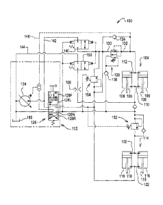
With reference to figure 1, hydraulic system 100 is shown. System 100 is
an implement hydraulic system coupled to a tractor hydraulic system 102. The
implement hydraulic system 100 includes an implement wing cylinder structure
104 shown with two cylinders 106. It should be understood that the wing
cylinder
structure 104 can have any number of cylinders 106 as desired. The implement
wing, and the implement wing cylinder structure is configured such that the
implement wings are lowered when the cylinder rods 108 are extended. However,
the implement could be constructed such that the implement wings are lowered
when the rods 108 are retracted. Thus, the hydraulic connections to the wing
cylinder structure will be referred to in the claims as connections to a first
end 110
or a second end 112 without regard to whether this is a reference to the cap
end
or rod end of the cylinders.
The hydraulic system 100 also includes an implement center frame
cylinders structure 114 shown as having two cylinders 116. Again, any number
of
cylinders 116 may be included in the center frame cylinder structure. The
implement center frame and center frame cylinder structure are constructed
such
that the implement is raised when the cylinder rods 118 are extended, and
lowered when the rods 118 are retracted. Again, the implement could be
structured such that the implement is raised when the rods 118 are retracted,
thus
the connections to the center frame cylinder structure will be referred to in
the
claims as connections to the first end or second end without regard to whether
this
reference is to the cap end or the rod end of the cylinders.
The first ends 110 and 120 of the wing cylinder structure and the center
frame cylinder structure are connected to the SCV in parallel. Likewise, the
3
CA 02737824 2011-04-19
second ends 112 and 122 of the wing cylinder structure and the center frame
cylinder structure are connected to the SCV in parallel.
The tractor hydraulic system 102 includes a load sense controlled pump
124 that provides flow to a selective control valve (SCV) 126. The selective
control
valve has a neutral position 126N, a first open position 126R used to raise
the
implement and wings, a second open position 126L used to lower the wings and
the implement, and a float position 126F. The SCV thus controls the raising
and
lowering of the implement.
A pressure reducing/relieving valve 128 regulates the pressure delivered to
the second end 112 of the wing cylinder structure 104. The pressure
reducing/relieving valve 128 has an inlet 130, an outlet 132 and a return
check
valve 134 that allows flow to bypass the pressure reducing/relieving valve 128
during retraction of the rods 108 of the wing cylinder structure. A drain
check valve
136 protects the pressure reducing/relieving valve during wing cylinder
structure
retraction.
A hydraulic latching function is provided in the circuit by first and second
dual-pilot-operated, two-way, two-position, normally-closed directional valves
140,
150. The first directional valve 140 is placed in a power beyond supply
connection
142 from the pump to the inlet 130 of the pressure reducing/relieving valve
128.
The second directional valve 150 is located in the power beyond return
connection
144 between first end 110 of the wing cylinder structure and the tank 160.
These
directional valves may be combined into one dual-pilot-operated, four-way, two-
position valve. A load sense pressure line 146 is provided between the outlet
132
of the valve 128 and the pump 124. The system 100 further includes first and
second sequence valves 152, 154. First sequencing valve 152 is in the parallel
connection to the first end 120 of the center frame cylinder structure. Second
sequencing valve 154 is in the parallel connection to the second end of the
wing
cylinder structure.
When the SCV 126 is actuated to raise the implement, that is, the SCV is
moved to the first open position 126R, the first sequence valve 152 prevents
the
center frame cylinder structure from extending until the sequence valve 152
set
pressure is reached. However, oil is allowed to enter the first end 110 of the
wing
4
CA 02737824 2011-04-19
cylinder structure. Oil freely exits the second end of the wing cylinder
structure
through the return check valve 134. Once the wing cylinder structure is fully
retracted, the supply pressure builds until the first sequence valve 152
opens.
Then the center frame cylinder structure extends.
When the SCV 126 is actuated to retract the center frame cylinders and
thus lower the implement, that is, the SCV is moved to the first open position
126L, Supply fluid is directed to the second ends 122 of the center frame
cylinder
structure. The sequence valve 152 bypass check valve allows free return of oil
from the first end of the center frame cylinder structure. Once the center
frame
cylinder structure is fully retracted, the supply pressure builds until the
second
sequence valve 154 set pressure is reached. When the second sequence valve
opens, oil pressure from the SCV is provided to the pilot of the directional
valves
140, 150 causing the directional valves to open. When directional valve 150 is
open, oil is allowed to freely exit the first end 110 of the wing cylinder
structure
allowing the rods 108 to extend and lower the implement wings. When the first
directional valve 140 is open, power beyond supply is connected to the second
end 112 of the wing cylinder structure and to the pilot port of the
directional valves
140, 150. This latches the power beyond pressure to the wing cylinder
structure to
provide active down force to the wing cylinder structure. Additionally, since
the
power beyond supply pressure is used to pilot the directional valves 140, 150
the
directional valves will remain open when the SCV 126 is returned to the
neutral
position 126N.
The directional valves remain open until the SCV 126 is actuated to the first
open position 126R to raise the implement or if the SCV is moved to the float
position 126F. When the SCV is moved to the first open position 126R, pilot
pressure provided to the directional valves 140, 150 closes the valves. When
the
SCV is moved to the float position 126F, the pilot pressures on the
directional
valves 140, 150 equalize, allowing the springs to close the directional
valves,
deactivating the down force circuit. If the directional valves 140, 150 are
open
during the start of an implement raise cycle, then oil would also flow through
the
orifice 156 and the second directional valve 150 to the power beyond return.
As
this oil flow increases, the orifice would cause ample pressure when coupled
with
5
CA 02737824 2011-04-19
the spring force to close the directional valve 150.
If power beyond is not available on the tractor, then the power beyond
supply ports to directional valve 140 and the power beyond return port to
directional valve 150 are plugged. The implement can then be operated with the
SCV. A down force mode then requires the SCV to be in the second open position
126L.
The system 100 provides a sequencing for the desired operation of the
center frame cylinder structure and the wing cylinder structure and also
provides
hydraulic latching to activate down force control on the wing cylinder
structure.
Turning to figure 2, another hydraulic system 200 is shown. In many
respects system 200 is identical to system 100. Similar or identical
components
are given the same reference numeral beginning with 2 instead of 1. System 200
uses the same sequencing as system 100 but it is a different latching circuit.
Here,
latching is accomplished by a normally-open, three-way, two-position, pilot-
operated, directional valve 240 and a normally-closed, four-way, two-position,
pilot-operated, directional valve 250. When the center frame cylinder
structure 214
is fully retracted, sequence valve 254 opens which pilots the directional
valve 250
open, opening the power beyond supply connection 242 to the pressure
reducing/relieving valve 228 to the second end 212 of the wing cylinder
structure.
When the SCV 226 is returned to the neutral/closed position, 226N, power
beyond
pressure continues to pilot the directional valve 250 open. When the SCV is
shifted to the first open position 226R to raise the implement, the
directional valve
240 is piloted closed. The valve 240 then cuts off power beyond supply from
the
valve 228 deactivates the down force the wings. The directional valve 250 is
also
returned to the closed position. Oil from the second end 212 of the wing
cylinder
structure returns through the check valve 234 and through the directional
valve
240 to the SCV and then to the tank 260.
The hydraulic systems use hydraulic latching to allow a load sense power
source to be activated and deactivated by the SCV. The load sense power source
is activated when the cylinders of the wing cylinder structure are fully
extended as
shown, or fully retracted. The load sense power source remains activated, that
is
latched, when the SCV is returned to neutral. It is deactivated or unlatched
when
6
CA 02737824 2011-04-19
the cylinders are retracted as shown.
Having described the hydraulic systems, it will become apparent that
various modifications can be made without departing from the scope of the
accompanying claims.
7