Note: Descriptions are shown in the official language in which they were submitted.
CA 02737838 2011-04-21
- 1 -
WIND POWER TURBINE ELECTRIC GENERATOR, AND WIND POWER
TURBINE EQUIPPED WITH SUCH AN ELECTRIC GENERATOR
The present invention relates to a wind power
turbine electric generator.
Preferably, the present invention relates to an
electric generator for a direct-drive wind power
turbine.
An electric generator normally comprises a tubular
first supporting structure extending about an axis of
rotation; a second supporting structure extending about
the axis of rotation, substantially coaxial with the
first supporting structure, and fitted to the first
supporting structure to rotate about the axis of
rotation; first active parts fitted to the first
supporting structure; and second active parts fitted to
the second supporting structure, facing the first active
parts, and separated from the first active parts by an
annular gap.
Electric generators of the above type are known and
used widely on wind power turbines. More recently,
permanent-magnet synchronous electric generators have
also been used, particularly on direct-drive wind power
turbines, i.e. comprising a blade assembly connected
directly to the electric generator, with no gearboxes in
between. Examples of direct-drive wind power turbines
CA 02737838 2011-04-21
- 2 -
equipped with permanent-magnet synchronous electric
generators are described in documents EP 1,425,840; EP
1,792,381; EP 2,102,496; EP 2,063,115; EP 2,063,116; EP
2,063,117; EP 2,143,938; EP 2,143,942; and EP 2,143,944.
Though direct-drive wind power turbines are more
efficient mechanically and cheaper to maintain than
gearbox types, and synchronous electric generators are
more efficient electrically than asynchronous types,
direct-drive wind power turbines are characterized by
fairly low rotation speed, which, combined with the need
for more and more electric power, makes it necessary to
employ permanent-magnet synchronous electric generators
with numerous poles and a high maximum torque, and
therefore large-size electric generators which can pose
structural problems.
The first supporting structure and first active
parts define the stator or rotor of the electric
generator, and the second supporting structure and
second active parts define the rotor or stator, so the
larger the electric generator is, the larger the first
and second supporting structures are. Moreover, because
it weighs on the wind power turbine structure as a
whole, the weight of the electric generator must be
maintained within given limits, over and above which a
larger, more expensive wind power turbine is needed.
Also, it is preferable that the first and second
CA 02737838 2011-04-21
3 -
supporting structure not be too massive or heavy.
The first supporting structure is often defined by
a tubular structure which, besides supporting the first
active parts, also defines a load-bearing structural
element of the wind power turbine as a whole, as shown,
for example, in EP 1,425,840 and EP 2,102,496. As a
result, the first supporting structure is subject to a
normally small amount of strain, particularly during
assembly but also possibly during operation of the
electric generator. Even a small amount of strain of the
first supporting structure, however, may have serious
effects, by modifying the annular gap between the first
and second active parts and so impairing operation of
the electric generator. The normal practice, in fact, is
to minimize the radial size of the annular gap to
increase the efficiency of the electric generator and
reduce flux dispersion, but it is often necessary to
oversize the annular gap to prevent strain of the first
supporting structure from affecting the electric
generator.
It is an object of the present invention to provide
an electric generator designed to reduce the drawbacks
of the known art.
Another object of the present invention is to
provide an electric generator designed to give maximum
efficiency when installed on a wind power turbine.
CA 02737838 2011-04-21
4 -
According to the present invention, there is
provided an electric generator for a wind power turbine;
the electric generator comprising :
- a tubular first supporting structure extending
about an axis of rotation;
- a second supporting structure extending about the
axis of rotation, substantially coaxial with the first
supporting structure, and fitted to the first supporting
structure to rotate about the axis of rotation;
- first active parts fitted to the first supporting
structure;
- second active parts fitted to the second
supporting structure, facing the first active parts, and
separated from the first active parts by an annular gap;
and
- a radial tensioning device designed to adjust the
shape of the first supporting structure about the axis
of rotation.
The circular shape of the first supporting
structure can thus be adjusted to control and if
necessary correct the radial size of the annular gap.
In a preferred embodiment of the present invention,
the radial tensioning device comprises an annular plate;
and a number of radial arms extending from the annular
plate to the first supporting structure.
The annular plate thus provides a high degree of
CA 02737838 2011-04-21
-
structural rigidity, while the radial arms allow forces
to be exchanged between different parts of the first
supporting structure, and permit local deformation of
the first supporting structure to correct any flaws in
5 its circular shape.
More specifically, each radial arm is connected to
the annular plate to slide radially with respect to the
axis of rotation, and is fixable to the annular plate.
In another preferred embodiment of the present
invention, the electric generator comprises a bearing
between the radial tensioning device and the second
supporting structure.
The radial tensioning device thus provides for
correcting the circular shape of the first supporting
structure, and coaxial alignment of the first and second
supporting structure.
A number of non-limiting embodiments of the present
invention will be described by way of example with
reference to the accompanying drawings, in which :
Figure 1 shows a side view, with parts removed for
clarity, of a wind power turbine;
Figure 2 shows a larger-scale, partly sectioned
side view, with parts removed for clarity, of the Figure
1 wind power turbine;
Figure 3 shows a larger-scale, partly sectioned
view in perspective, with parts removed for clarity, of
CA 02737838 2011-04-21
6 -
a detail in Figure 2;
Figure 4 shows a front view, with parts removed for
clarity, of a detail in Figure 2;
Figure 5 shows a partly sectioned view in
perspective, with parts removed for clarity, of an
alternative embodiment of the present invention.
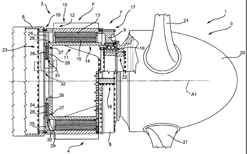
Number 1 in Figure 1 indicates as a whole a direct-
drive wind power turbine for generating electric power,
and which comprises a vertical support 2; a nacelle 3;
an electric generator 4; and a rotary assembly 5 fitted
to nacelle 3 to rotate about an axis of rotation Al.
Nacelle 3 is in turn fitted to vertical support 2 to
rotate about an axis of rotation A2; and, in the example
shown, electric generator 4 is a permanent-magnet
synchronous electric generator.
Nacelle 3 is substantially a tubular member
supporting rotary assembly 5, which extends partly
inside and partly outside nacelle 3. In the example
shown, nacelle 3 comprises a curved tubular member 6;
part of electric generator 4; and a ring 7 comprising
two complementary sectors 8 and 9 connected about axis
of rotation Al.
With reference to Figure 2, electric generator 4 is
tubular, and comprises a stator 10 and a rotor 11.
Stator 10 comprises a tubular supporting structure 12;
and active parts 13 - in the example shown, stator
CA 02737838 2011-04-21
7 -
segments - arranged about axis of rotation Al and fixed
to the inner face of supporting structure 12. Rotor 11
comprises a tubular supporting structure 14; and active
parts 15 - in the example shown, rotor segments -
arranged about axis of rotation Al and fixed to the
outer face of supporting structure 14. And nacelle 3,
more specifically, comprises curved tubular member 6;
stator 10, or rather supporting structure 12 of stator
10; and ring 7.
Active parts 13 comprise stator segments parallel
to axis of rotation Al. Each stator segment comprises a
magnetic gap and at least one electric winding, and is
of the type described in EP 1,792,381.
Active parts 15 comprise rotor segments parallel to
axis of rotation Al. Each rotor segment comprises a
magnetic gap and permanent magnets, and is of the type
described in EP 1,792,381.
Supporting structure 12 has two opposite flanged
ends fixed to curved tubular member 6 and ring 7 by
respective bolted joints 16 and 17. More specifically,
ring 7 is fitted slidably to supporting structure 12,
and is locked in position by bolted joint 17. More
specifically, sectors 8 and 9 are each semicircular in
shape, and are connected by two bolted joints 18 to form
ring 7. In the example shown, sector 8 is located below
sector 9. Wind power turbine 1 comprises a bearing 19
CA 02737838 2011-04-21
- 8 -
between nacelle 3 and rotary assembly 5. In the example
shown, wind power turbine 1 comprises a single bearing
19 capable of withstanding axial and radial stress
between nacelle 3 and rotary assembly 5; it being
understood, however, that the specific configuration
shown in the drawings and described herein in no way
limits the protective scope of the present invention.
Bearing 19 is fitted to the inside of ring 7, is fixed
directly to sectors 8 and 9 in the example shown, and is
fixed to the outside of rotary assembly 5.
Rotary assembly 5 comprises rotor 11, a hub 20, and
blades 21 fitted to hub 20. In the example shown, rotary
assembly 5 also comprises a connecting member 22 located
between rotor 11 and hub 20, and at and substantially
inside bearing 19. More specifically, bearing 19 is
fixed directly to connecting member 22; and hub 20 is
connected directly to rotor 11, which rotates at the
same speed as hub 20.
Electric generator 4 generally comprises supporting
structure 12, which extends about axis of rotation Al;
supporting structure 14, which extends about axis of
rotation Al, is substantially coaxial with supporting
structure 12, and is fitted to supporting structure 12
to rotate about axis of rotation Al; active parts 13
fitted to supporting structure 12; and active parts 15
fitted to supporting structure 14, facing active parts
CA 02737838 2011-04-21
9 -
13, and separated from active parts 13 by an annular
gap. Electric generator 4 also comprises a radial
tensioning device 23 designed to adjust the shape of
supporting structure 12 about axis of rotation Al, i.e.
to correct any deformation, ovalization, or any other
flaw in the circular shape of the inner face of
supporting structure 12, so as to maintain as circular a
shape as possible of supporting structure 12.
In the example shown, radial tensioning device 23
is located inside supporting structure 12 and is annular
in shape.
More specifically, and as shown in Figure 3, radial
tensioning device 23 comprises an annular plate 24; and
a number of radial arms 25 extending from annular plate
24 to supporting structure 12, and equally spaced about
axis of rotation Al.
Each radial arm 25 is connected to annular plate 24
to slide radially with respect to axis of rotation Al
(Figure 2), and is fixable to annular plate 24.
Radial tensioning device 23 comprises a number of
adjusting mechanisms 26, each associated with a
respective radial arm 25 to slide radial arm 25 radially
with respect to annular plate 24. That is, annular plate
24 comprises a number of seats 27, each for housing a
respective radial arm 25; each adjusting mechanism 26
comprises a screw 28 housed inside annular plate 24 and
CA 02737838 2011-04-21
- 10 -
for pushing respective radial arm 25 outwards against
supporting structure 12; and each radial arm 25 is fixed
releasably to supporting structure 12.
Each radial arm 25 comprises a projection 29
located between supporting structures 12 and 14, close
to supporting structure 14, and designed to prevent
relative radial movements between supporting structures
12 and 14. In other words, projection 29 is made of low-
friction material to permit relative rotation between
supporting structures 12 and 14, even when projection 29
is positioned contacting supporting structure 14.
With reference to Figure 2, active parts 13 and
active parts 15 are in the form of segments extending
parallel to axis of rotation Al, and are equal in
number. The number of radial arms 25 is less than or
equal to the number of active parts 13 and active parts
15, so that removal of one radial arm 25 extracts at
least one segment of active parts 13 or one segment of
active parts 15. The number of radial arms 25 may even
be a multiple of, e.g. twice, the number of active
parts, so that removing two radial arms 25 extracts a
segment of active parts 13 or a segment of active parts
15, though this solution is not as advantageous as the
previous one.
Accordingly, annular plate 24 has an outer edge 30
smaller in diameter than the maximum diameter of
CA 02737838 2011-04-21
- 11 -
supporting structure 12, so as not to obstruct
extraction of the segments of active parts 15; and an
inner edge 31 defining a manhole opening.
With reference to Figure 3, electric generator 4
comprises a brake 32; and locking devices 33 (only one
shown in Figure 3) arranged about axis of rotation Al.
Brake 32 comprises a brake disk 34; and a number of
brake calipers 35 (only one shown in Figure 3) arranged
about axis of rotation Al. Brake disk 34 is integral
with supporting structure 14, and is defined by an
annular plate parallel to annular plate 24 and extending
inside supporting structure 14. Each brake caliper 35
comprises a frame 36 fixed to annular plate 24; two jaws
37 mounted on opposite sides of brake disk 34; and an
actuating mechanism 38 for activating jaws 37 (only one
shown in Figure 3) to selectively grip brake disk 34.
Each locking device 33 comprises a pin 39; and an
actuator 40 fixed to annular plate 24 to move pin 39
between a rest position (Figure 3) and a work position
(not shown). And brake disk 34 comprises a number of
holes 41 arranged about axis of rotation Al and engaged
by pin 39 when pin 39 is in the work position.
Figure 4 shows electric generator 4 in a locked
configuration, i.e. in which locking devices 33 lock
supporting structures 12 and 14 with respect to each
other. Also, electric generator 4 is less one radial arm
CA 02737838 2011-04-21
- 12 -
25 and fitted with an extracting device 42, which is
fitted to the two radial arms 25 adjacent to the missing
radial arm 25, and serves to extract a segment of active
parts 13 and/or 15 at the missing radial arm.
The outer face of supporting structure 12 is fitted
with cooling fins F.
In Figure 5, radial tensioning device 23 is
replaced by a radial tensioning device 43, which, in
addition to correcting the circular shape of supporting
structure 12, also serves to connect supporting
structures 12 and 14 in rotary manner about axis of
rotation Al.
Like radial tensioning device 23, radial tensioning
device 43 comprises an annular plate 44; and a number of
radial arms 45 extending from annular plate 44 to
supporting structure 12, and equally spaced about axis
of rotation Al. Each radial arm 45 is connected to
annular plate 44 to slide radially with respect to axis
of rotation Al (Figure 2), and is fixable to annular
plate 44. Radial tensioning device 43 comprises a number
of adjusting mechanisms 46, each associated with a
respective radial arm 45 to slide radial arm 45 radially
with respect to annular plate 44. In the Figure 5
example, annular plate 44 comprises openings 47 designed
and located to enable use of adjusting mechanisms 46
similar to adjusting mechanisms 26. And annular plate 44
CA 02737838 2011-04-21
- 13 -
comprises an outer edge 48 and an inner edge 49 of the
same size as outer edge 30 and inner edge 31 (Figure 3).
Electric generator 4 comprises a bearing 50 between
radial tensioning device 43 and supporting structure 14.
That is, inner edge 49 of radial tensioning device 43
contacts bearing 50; and rotor 11 comprises a ring 51
located inside bearing 50, and a flange 52 connecting
ring 51 to supporting structure 14. Electric generator 4
also comprises a disk 53 fixed to ring 51, and which may
also be used as a brake disk. Generally speaking, radial
tensioning device 43 can be fitted with a brake and
locking devices 33 as shown in Figures 3 and 4 of the
previous embodiment of the invention.
The radial tensioning device in the Figure 5
embodiment provides for simultaneously adjusting the
circular shape of supporting structure 12, and coaxial
alignment of supporting structures 12 and 14.
Clearly, changes may be made to the electric
generator and wind power turbine as described herein
without, however, departing from the scope of the
accompanying Claims.
More specifically, in a variation not shown, ring 7
is eliminated, and stator 10 and bearing 19 are
connected in accordance with alternative embodiments, as
described, for example, in Patent EP 1,425,840.
In the above description, specific reference is
CA 02737838 2011-04-21
- 14 -
made repeatedly, for the sake of simplicity, to bolted
joints, which are intended to mean joints made using
bolts and nuts, or screws screwed directly into one of
the parts for connection, and may be replaced by any
other type of releasable joint.