Note: Descriptions are shown in the official language in which they were submitted.
CA 02738021 2011-08-12
CONVEYOR CHAIN
Randall Lee Morris
[0001]
BACKGROUND
[00021 Pusher-type chain conveyors, as used in the mining industry, are
found both in the
form of separate conveying units, and as integral parts of continuous mining
machines. One example of a continuous mining machine is a self-propelled
mining machine. It is provided at its forward end with cutting means shiftable
in
such a way that an entry is cut in the material being mined. The entry is so
sized
as to permit passage of the mining machine therethrough. Since the cutting
operation is a continuous one, it is advantageous to provide means to move the
cut
material from in front of the mining machine and to convey it out of the
entry.
[00031 One or several conveyors may be incorporated into the mining
machine's
construction that act successively to transport the cut material rearwardly
from the
rn2rhine. One example of a conveyor that is incorporated into the mining
machine
extends from the front to the rear of the machine. The purpose of this
conveyor is
to remove the cut material from entry and deliver the cut material to other
conveying means. The other conveying means may comprise mine cars or other
vehicles used for hauling, portable belt conveyors or other conveyors designed
for
loading and unloading mined material from the mining machine, or the like.
CA 02738021 2013-09-20
[0004] An example of a conveyor that has been encountered in association
with a
continuous mining machine includes a section of conveyor base means mounted
on the mining machine body. One or more additional sections of conveyor base
means are connected thereto end-to-end, and extend beyond the rearward end of
the mining machine body. All of the base means sections are characterized by a
bottom portion provided with longitudinally extending, upstanding side guides
or
flanges. The various sections of the tail conveyor can be capable of both
lateral
and vertical movement with respect to each other, which enables the cut
material
to be delivered to a desired point despite changes of position of the mining
machine as it advances in the entry and changes in level of the entry floor.
The
lateral and vertical movement capability of the conveyor sections may also
enable the shifting of the desired delivery point for the material being
mined, as
required.
[0005] This type of conveyor may incorporate a continuous pusher-type
conveyor chain,
which is driven along the length of the conveyor base sections. The chain may
be
provided with a plurality of rigid pusher elements, normally extending
substantially transversely of the conveying direction. The pusher elements are
located at spaced intervals along the chain. Adjacent pusher elements may be
joined together by a series of alternate block-like links and plate-like
links. At
one end of the machine's conveyor, the continuous chain passes over a driven
sprocket. At the other end of the conveyor, the chain passes over a driven or
idler
sprocket, or roller.
[0006] Various embodiments of a conveyor chain configured to be used in
conjunction
with a dual drive sprocket on a mining machine are disclosed in PCT Published
Application WO 2002/028750 dated April 11, 2002 and US Patent No.
8,016,102 issued September 13, 2011.
2
CA 02738021 2013-09-20
[0006.1] According to one aspect of the present invention there is provided
a conveyor
chain for being driven by at least two drive sprockets, the conveyor chain
comprising a plurality of side link assemblies and flight arm assemblies
coupled
together to form an elongated chain; at least one flight arm assembly
including a
pair of opposing flight arms positioned on either side of the chain, the
flight arms
each comprising: an elongated body and an integral base formed with the
elongated body, the elongated body extending substantially perpendicular from
the integral base; a vertical sprocket opening formed in the integral base and
configured to extend vertically through the integral base, the vertical
sprocket
opening being shaped to engage a tooth of a drive sprocket so that the tooth
acts
on the integral base to drive the flight arm; integral bases of the opposing
flight
arms configured to engage a respective tooth of a drive sprocket positioned on
either side of the chain for driving the flight arm assembly on both sides of
the
chain; at least one side link assembly including a pair of opposing side
straps
positioned on either side of the chain, the side straps each comprising, a
base; at
least a pair of side strap bosses extending outwardly from the base; at least
one
of the side strap bosses being configured to engage a tooth of a drive
sprocket so
that the tooth acts on the side strap boss to drive the side strap; side strap
bosses
of the opposing side straps configured to engage a respective tooth of a drive
sprocket positioned on either side of the chain for driving the side link
assembly
on both sides of the chain.
[0006.2] According to a further aspect of the present invention there is
provided a
conveyor system comprising a driving member, the driving member including a
first drive sprocket and second drive sprocket, each of the first drive
sprocket and
the second drive sprocket having a plurality of teeth; a conveyor chain for
being
driven by the drive sprockets of the driving member; the conveyor chain
comprising: a plurality of side link assemblies and flight arm assemblies
coupled
together to form the chain; at least one flight arm assembly including a pair
of
opposing flight arms positioned on either side of the chain, the flight arms
each
comprising: an elongated body and an integral base formed with the elongated
body, the elongated body extending substantially perpendicular from the
integral
base; a vertical sprocket opening formed in the integral base and configured
to
2a
CA 02738021 2013-09-20
extend vertically through the integral base, the vertical sprocket opening
being
shaped to engage a tooth of a drive sprocket so that the tooth acts on the
integral
base to drive the flight arm; integral bases of the opposing flight arms
configured
to engage a respective tooth of the first and second drive sprockets
positioned on
opposing sides of the chain; at least one side link assembly including a pair
of
opposing side straps positioned on either side of the chain, the side straps
each
comprising, a base; at least a pair of side strap bosses extending outwardly
from
the base; at least one of the side strap bosses being configured to engage a
tooth
of a drive sprocket so that the tooth acts on the side strap boss to drive the
side
strap; side strap bosses of the opposing side straps configured to engage a
respective tooth of the first and second drive sprockets positioned on
opposing
sides of the chain.
2b
CA 02738021 2011-03-21
WO 2010/033893
PCT/US2009/057635
[0007] While a variety of conveyor chains have been made and used, it is
believed that
no one prior to the inventor has made or used an invention as described
herein.
BRIEF DESCRIPTION OF THE DRAWINGS
[0008] While the specification concludes with claims which particularly
point out and
distinctly claim the invention, it is believed the present invention will be
better
understood from the following description of certain examples taken in
conjunction with the accompanying drawings, in which like reference numerals
identify the same elements and in which:
[0009] Fig. 1 depicts a perspective view of a segment of an exemplary
conveyor chain.
[00010] Fig. 2 depicts a perspective view of an exemplary side strap.
[00011] Fig. 3 depicts a perspective view of an exemplary flight pin.
[00012] Fig. 4 depicts a perspective view of an exemplary universal link.
[00013] Fig. 5 depicts a perspective view of an exemplary connector link.
[00014] Fig. 6 depicts a perspective view of an exemplary universal
connector assembly.
[00015] Fig. 7 depicts a side cross-sectional view of the exemplary
universal connector
assembly of Figure 6.
[00016] Fig. 8 depicts a top plan view of an exemplary flight arm.
[00017] Fig. 9 depicts a side elevation view of the exemplary flight arm of
Figure 8.
[00018] Fig. 10 depicts an end view of the exemplary flight arm of Figure
8.
[000191 Fig. 11 depicts a perspective view of an exemplary connecting pin.
3
CA 02738021 2011-03-21
WO 2010/033893 PCT/US2009/057635
[00029] Fig. 12 depicts a perspective view of a section of exemplary
conveyor chain
engaged with an exemplary driving member comprising a dual drive sprocket.
[00021] Fig. 13 depicts a perspective view of a section of exemplary
conveyor chain
engaged with an exemplary driving member comprising a triple drive sprocket.
[00022] The drawings are not intended to be limiting in any way, and it is
contemplated
that various embodiments of the invention may be carried out in a variety of
other
ways, including those not necessarily depicted in the drawings. The
accompanying drawings incorporated in and forming a part of the specification
illustrate several aspects of the present invention, and together with the
description serve to explain the principles of the invention; it being
understood,
however, that this invention is not limited to the precise arrangements shown.
DETAILED DESCRIPTION
[00023] The following description of certain examples of the invention
should not be used
to limit the scope of the present invention. Other examples, features,
aspects,
embodiments, and advantages of the invention will become apparent to those
skilled in the art from the following description, which is by way of
illustration,
one of the best modes contemplated for carrying out the invention. As will be
realized, the invention is capable of other different and obvious aspects, all
without departing from the invention. Accordingly, the drawings and
descriptions
should be regarded as illustrative in nature and not restrictive.
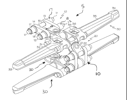
[000241 As shown in figure 1, a section of conveyor chain (5) comprises two
side link
assemblies (10), four connector assemblies (20) (one is not shown in figure
1),
and two flight arm assemblies (30). Of course, conveyor chain (5) may comprise
any suitable number of side link assemblies, connector assemblies, and flight
assemblies to produce a chain of sufficient length for a particular
application. It
will be appreciated that side strap (13) may be virtually identical to side
strap (14).
In the illustrated embodiment, each universal connector assembly (20)
comprises
4
CA 02738021 2011-03-21
WO 2010/033893 PCT/US2009/057635
a universal link (22) and a connector link (23) with a universal pin (21)
extending
through the universal link (22) and the connector link (23). As shown in
figure 1,
each flight arm assembly (30) comprises a pair of flight arm pins (31, 32) and
a
pair of flight arms (33, 34).
1000251 In the illustrated embodiment, the two side straps (13, 14) of each
side link
assembly (10) are spaced apart and positioned so that the two side strap
bosses
(17, 18) are facing outwardly. In this example, each side strap boss (17, 18)
comprises a hollow circular protrusion that includes an opening (19) that
extends
through the side strap boss (17, 18) and base (15). Each side strap boss (17,
18) is
configured to receive at least a portion of a connecting pin (11, 12). Of
course,
side strap bosses (17, 18) may comprise any suitable shape, including but not
limited to circular and square. As shown in figures 12 and 13, the side strap
bosses (17, 18) are configured to engage a tooth (102) of a sprocket such as
one of
sprockets (104a, 104b) of drive mechanism (100) or outer sprockets (204a,
204b)
of drive mechanism (200) when the chain is engaged and driven by a driving
member, such as a dual drive sprocket (100), a triple drive sprocket (200) or
any
other suitable driving member. In the illustrated embodiment, the side strap
(13)
in each side link assembly (10) is aligned with side strap (14) such that each
side
strap boss (17, 18) of side strap (13) is aligned with a corresponding side
strap
boss (17, 18) of side strap (14). In this example, a first connecting pin (11)
is
inserted through the aligned side strap bosses (17) in side straps (13, 14),
while a
second connecting pin (12) is inserted through the aligned side strap bosses
(18)
in side straps (13, 14). Collectively, the side straps (13, 14) and connecting
pins
(11, 12) form a side link assembly (10). The diameter of the connecting pin
(11,
12) may be about 1 1/8 inch, or any other suitable dimension. By way of
example
only, in some embodiments the diameter of the connecting pin (11, 12) may
range
from about 1 inch to about 1 1/4 inch. Increasing the diameter of the
connecting
pins (11, 12) compared to bearing pins used in existing conveyor chains may
improve the strength and reliability of the conveyor chain during operation
while
reducing the chance of chain breakage The connecting pins (11, 12) and side
strap bosses (17, 18) may be configured to provide a press fit, a sliding
close
CA 02738021 2011-03-21
WO 2010/033893
PCT/US2009/057635
tolerance fit, or any other suitable fit between the components. Connecting
pins
(11, 12) may be retained within side strap bosses (17, 18) by keeper pins,
retaining rings, by press fit alone, or by any other suitable method or
device.
[00026] Figures 4-7 depict one embodiment of a universal connector assembly
(20). In
the illustrated embodiment, universal connector assembly (20) comprises a
universal pin (21), a universal link (22), and a connector link (23). The
universal
link (22) as pictured in figure 4, comprises an upper lip (41) and lower lip
(42)
each having a vertical thru-hole (43, 44) that is configured to receive at
least a
portion of the universal pin (21). The universal link (22) can also be
described as
the female link. In this example, universal link (22) further comprises
connecting
portion (45) that extends between upper lip (41) and lower lip (42). As shown,
connecting portion (45) is rounded and is configured to receive at least a
portion
of a connecting pin (11, 12) or a flight pin (31,32). In the illustrated
embodiment,
connector link (23) comprises a projecting member (51) sized and shaped to fit
between the upper lip (41) and lower lip (42) of the universal link (22) as
shown
in Figure 6. The connector link (23) can also be described as a male link. In
this
version, projecting member (51) includes a vertical thru-hole (52) that is
configured to receive a universal pin (21). In this example, connector link
(23)
further comprises a horizontal opening (53) that extends through the width of
connector link (23) is configured to receive at least a portion of a
connecting pin
(11, 12) or a flight pin (31, 32).
[00027] As shown in figures 6 and 7, when universal connector assembly (20)
is fully
assembled, the projecting member (51) of the connector link (23) is inserted
between the upper lip (41) and lower lip (42) of the universal link (22). In
this
example, vertical thru-holes (42, 43) of the universal link (22) are axially
aligned
with vertical thru-hole (52) of the connector link, such that the universal
pin (21)
may pass through the vertical thru-holes (42, 43, 52) as shown in figures 6
and 7.
The universal pin (21) may be configured to increase mobility of the chain,
allow
6
CA 02738021 2011-03-21
WO 2010/033893
PCT/US2009/057635
the chain to articulate past objects, and reduce the load transmitted to the
connecting pins (11, 12) when an obstruction in a conveying deck is
encountered.
[00028] As shown in figure 1, flight assembly (30) comprises a pair of
flight pins (31, 32)
and a pair of flight arms (33, 34). In this example, each flight arm (33, 34)
comprises an elongated body (35) extending substantially perpendicular from a
base (36). In this version, each base (36) includes a pair of flight arm
attachment
apertures (37, 38) that extend transversely through the base (36). Each flight
arm
attachment aperture (37, 38) may be configured to receive at least a portion
of one
of the flight arm pins (31, 32), As shown, each base (36) further comprises a
vertical sprocket opening (39) that extends vertically through the base (36).
The
diameter of the flight pin may be about 1 1/8 inch, or any other suitable
dimension. By way of example only, in some embodiments the diameter of the
connecting pin (31, 32) may range from about 1 inch to about 1 'A inch.
Increasing the diameter of the flight pins (31, 32) compared to bearing pins
used
in existing conveyor chains may improve the strength and reliability of the
conveyor chain during operation while reducing the chance of chain breakage.
The flight pins (31, 32) and bases (36) may be configured to provide a press
fit, a
sliding close tolerance fit, or any other suitable fit between the components.
Flight pins (31, 32) may be retained within the flight arm attachment
apertures
(37, 38) of bases (36) by keeper pins, retaining rings, by press fit alone, or
by any
other suitable method or device.
[00029] As shown in figures 8-10, flight arm (33, 34) comprises an
elongated body (35)
having a flat, planar bottom surface (91) and an integral base (36). In this
version,
elongated body (35) comprises a central rib (81) that may act as a pusher for
the
material being conveyed. In this example, the outer free end of flight arm
(33, 34)
is provided with a knob-like portion (82) which can ride against side guide
elements associated with conveyors. The base (36) may be provided with a
vertical sprocket opening (39). As shown in figures 12 and 13, sprocket
opening
(39) is sized and shaped to engage a tooth (102) of a sprocket such as one of
7
CA 02738021 2011-03-21
WO 2010/033893 PCT/US2009/057635
sprockets (104a, 104b) of driving member (100) or sprockets (204a, 204b) of
driving member (200) when the chain is engaged and driven by a driving
member, such as a dual drive sprocket (100), a triple drive sprocket (200) or
any
other suitable driving member. While sprocket opening (39) is substantially
rectangular in the illustrated embodiment, it will be appreciated that
sprocket
opening (39) may comprise any suitable shape configured to receive and engage
a
tooth (102), including but not limited to circular, oval, square, and
rectangular. In
the illustrated version, base (36) also comprises two flight arm attachment
aperture (37, 38). As shown in figure 1, flight arm (33) in each flight arm
assembly (30) is aligned with flight arm (34) such that the flight arm
attachment
apertures (37, 38) of flight arm (33) are aligned with the flight arm
attachment
apertures (37, 38) of flight arm 34. In this example, a first flight pin (31)
is
inserted through the aligned flight arm attachment apertures (37) in flight
arms
(33, 34), while a second flight pin (32) is inserted through the aligned
flight arm
attachment apertures (38) in flight arms (33, 34). In addition, each of the
flight
pins (31, 32) are inserted through horizontal openings (53) of a pair of
connector
links (23) positioned between the flight arms (33, 34).
[00030] As shown in figure 1, section of conveyor chain (5) comprises a
plurality of
alternating side link assemblies (10) and flight arm assemblies (30) connected
by
connector assemblies (20). In this version, each universal connector assembly
(20)
is configured and arranged to be connected to both a side link assembly (10)
and a
flight arm assembly (30). In this example, conveyor chain (5) comprises a side
link assembly (10) connected to a first universal connector assembly (20), a
flight
arm assembly (30) connected to both the first universal connector assembly
(20)
and a second universal connector assembly (20), and the second universal
connector assembly (20) is connected to a second side link assembly (10) and
so
on in a repeating pattern. While the illustrated version depicts a chain
comprising
alternating side strap assemblies (10) and flight arm assemblies (30), it will
be
appreciated that a section of chain may comprise any suitable arrangement of
side
strap assemblies (10) and flight arm assemblies (30). By way of example only,
in
8
CA 02738021 2011-03-21
WO 2010/033893
PCT/US2009/057635
an alternate embodiment (not shown), a section of conveyor chain may comprise
two side strap assemblies positioned between a pair of flight arm assemblies.
As
shown in figure 1, a side link assembly (10) is connected to a universal
connector
assembly (20) via a connecting pin (12). In this version, connecting pin (12)
is
positioned such that it passes through the aligned side strap bosses (18) of
side
straps (13, 14) and the opening formed by connecting member (45) of universal
link (22). Alternatively, a side link assembly (10) may be connected to a
universal
connector assembly (20) via a connecting pin (11) such that connecting pin
(11) is
positioned so that it passes through the aligned side strap bosses (17) of
side
straps (13, 14) and the horizontal opening (53) in connector link (23).
Similarly,
flight assembly (30) may be connected to a universal connector assembly (20)
by
positioning a flight pin (31, 32) through a pair of aligned flight arm
attachment
apertures (37, 38) in two opposing flight aims (33, 34) and the horizontal
opening
(53) in connector link (23). Alternatively, a flight assembly (30) may be
connected to a universal connector assembly (20) by positioning a flight pin
(31,
32) through a pair of aligned flight arm attachment apertures (37, 38) in two
opposing flight arms (33, 34) and the opening formed by connecting member (45)
in a universal link (22).
[00031] As shown in Figure 12, conveyor chain (105) is driven by a driving
member
(100). In this example, driving member (100) comprises a dual drive sprocket
that includes sprockets (104a, 104b). It will be appreciated that driving
member
(100) may comprise any suitable number of sprockets, including but not limited
to
a dual drive sprocket as shown in figure 12, a triple drive sprocket as shown
in
figure 13, or any other suitable number of sprockets. It will further be
appreciated
that driving member may comprise any suitable size sprockets, including but
not
limited to a four tooth sprocket, five tooth sprocket, a six-tooth sprocket,
an eight
tooth sprocket, and various combinations thereof. Use of a dual drive
sprocket,
such as driving member (100) shown in figure 12, and a corresponding conveyor
chain configured to be used with a dual drive sprocket, such as conveyor
chains
(5, 105, 205), may reduce operational noise and improve sprocket tooth life.
The
9
CA 02738021 2011-03-21
WO 2010/033893
PCT/US2009/057635
two sprockets (104a, 104b) comprising driving member (100) may be
substantially identical to each other and configured to rotate in unison with
each
other. By way of example only, in the embodiments shown in figure 12,
sprockets (104a, 104b) are each eight-tooth sprockets.
[000321 As shown, sprockets (104a, 104b) are spaced apart so that they are
aligned with
the side strap bosses (17, 18) and the vertical sprocket openings (39) along
each
side of the chain (105). In the illustrated embodiment, as conveyor chain
(105)
wraps around driving member (100), each sprocket tooth (102) engages a side
strap boss (17, 18) or the base (36) of a flight arm (33, 34) via a vertical
sprocket
opening (39) along both sides of the chain (105). As shown, a first sprocket
tooth
(102) may abut a first side strap boss (17), while a second sprocket tooth
(102)
may abut a second side strap boss (18), while a third sprocket tooth (102) may
be
received by and extend at least partially through a vertical sprocket opening
(39).
Although not shown in figure 12, additional sprocket teeth may engage
additional
side strap bosses and vertical sprocket openings as the chain wraps around the
dual sprocket. In the illustrated embodiment, the sprocket teeth (102) do not
directly engage or contact connecting pins (11,12) or flight pins (31, 32).
Because
the points of engagement between conveyor chain (105) and sprocket teeth (102)
(i.e. side strap bosses (17, 18) and flight arm bases (36)) are thicker than
the
points of engagement in some prior art conveyor chains (where sprocket teeth
directly engage bearing pins in the chain), conveyor chain (105) may provide
improved chain life and strength.
1000331 As shown in Figure 13, conveyor chain (205) is driven by a driving
member
(200). In this example, driving member (200) comprises a triple drive sprocket
that includes two outer sprockets (204a, 204b) and a central sprocket (204c).
It
will be appreciated that driving member (200) may comprise any suitable number
of sprockets, including but not limited to a dual drive sprocket as shown in
figure
12, a triple drive sprocket as shown in figure 13, or any other suitable
number of
sprockets. It will further be appreciated that driving member may comprise any
CA 02738021 2011-03-21
WO 2010/033893
PCT/US2009/057635
suitable size sprockets, including but not limited to a four tooth sprocket,
five
tooth sprocket, a six-tooth sprocket, an eight tooth sprocket, and various
combinations thereof. Use of a triple drive sprocket, such as driving member
(200) shown in figure 13, and a corresponding conveyor chain configured to be
used with a triple drive sprocket, such as conveyor chains (5, 105, 205), may
reduce operational noise and improve sprocket tooth life. The two outer
sprockets
(204a, 204b) may be substantially identical to each other, while central
sprocket
(204c) may be configured to have half as many sprocket teeth as outer
sprockets
(204a, 204b). Other suitable relationships between the outer sprockets and the
central sprocket may be apparent to those of ordinary skill in the art. All
three
sprockets (204a, 204b, 204c) may be configured to rotate in unison with each
other. By =way of example only, in the embodiment shown in figure 13, outer
sprockets (204a, 204b) are each eight-tooth sprockets and central sprocket
(204e)
is a four-tooth sprocket.
[00034] As
shown, outer sprockets (204a, 204b) are spaced apart so that they are aligned
with the side strap bosses (17, 18) and the vertical sprocket openings (39)
along
each side of the chain (205). Also, in this example, central sprocket (204c)
is
positioned so that the teeth (102) of central sprocket (204c) are received in
the gap
between adjacent universal connector assemblies (20) and engage a universal
connector assembly (20). In the illustrated embodiment, as conveyor chain
(205)
wraps around driving member (200), each sprocket tooth (102) of the outer
sprockets (204a, 204b) engages a side strap boss (17, 18) or the base (36) of
a
flight arm (33, 34) via a vertical sprocket opening (39) along both sides of
the
chain (205). At the same time, each sprocket tooth (102) of central sprocket
(204c) engages a universal connector assembly (20) along the central
longitudinal
axis of the chain (205). As shown, a first sprocket tooth (102) of an outer
sprocket (204a, 204b) may abut a first side strap boss (17), while a second
sprocket tooth (102) of an outer sprocket (204a, 204b) may abut a second side
strap boss (18), while a third tooth (102) of an outer sprocket (204a, 204b)
may be
received by and extend at least partially through a vertical sprocket opening
(39).
11
CA 02738021 2011-03-21
WO 2010/033893 PCT/US2009/057635
At the same time, a first sprocket tooth (102) of central sprocket (204c) may
be
received by and extend at least partially through an opening between a first
pair of
adjacent universal connector assemblies (20), while a second sprocket tooth
(102)
of central sprocket (204c) may be received by and extend at least partially
through
an opening between a second pair of adjacent universal connector assemblies
(20). Although not shown in figure 13, additional sprocket teeth (102) on
outer
the outer sprockets (204a, 204h) may engage additional side strap bosses and
vertical sprocket openings and additional sprocket teeth (102) on central
sprocket
(204c) may engage additional openings between additional pairs of adjacent
universal connector assemblies (20) as the chain wraps around the driving
member (200). In the illustrated embodiment, the sprocket teeth (102) do not
directly engage or contact connecting pins (11,12) or flight pins (31, 32).
Because
the points of engagement between conveyor chain (205) and sprocket teeth (102)
(i.e. side strap bosses (17, 18), flight arm bases (36), and universal
connector
assemblies (20)) are thicker than the points of engagement in some prior art
conveyor chains (such as chains where sprocket teeth directly engage bearing
pins
in the chain), conveyor chain (205) may provide improved chain life and
strength.
[00035] In an alternate embodiment (not shown), the driving member may
comprise a
single sprocket, such as central sprocket (204c) described above. In such an
embodiment, the single sprocket may be positioned and configured to engage the
chain by having the teeth of the sprocket received between adjacent universal
connector assemblies, similar to the central sprocket (204c) described above.
[00036] A conveyor chain, such as conveyor chains (5, 105), may comprise an
even pitch
along substantially the entire length of the conveyor chain, although this is
not
required. The pitch may comprise the distance between adjacent connecting pins
(11, 12) and flight pins (31, 32). In one embodiment, the pitch may comprise
about 3 1/2 inches, although any suitable pitch may be used depending on the
particular application. By way of example only, the pitch may also range from
about 1 inch to about 5 inches in length, or more particularly from about 2
i/2
12
CA 02738021 2011-03-21
WO 2010/033893 PCT/US2009/057635
inches to about 4 1/2 inches in length. A conveyor chain with an even pitch
may
provide for an increased number of sprocket teeth engaged with the chain and
may allow for the use of a driving member that comprises two or more
individual
sprockets.
[00037] It should be appreciated that the various components may be
comprised of any
suitable material known in the art that exhibits the requisite strength and
durability characteristics based on the intended application of the chain. By
way
of example only, the various components may comprise forged steel, cast steel,
spring steel, composite steel, plastic, other suitable materials and
combinations
thereof Each of the components may comprise the same material, or
alternatively, different components may comprise different materials. In
addition,
by way of example only the flight arms (33, 34) or any other suitable
components,
may be made of composite steel and plastic, urethane, or other material that
can
reduce noise levels during operation, although this is not required.
[00038] Having shown and described various embodiments of the present
invention,
further adaptations of the methods and systems described herein may be
accomplished by appropriate modifications by one of ordinary skill in the art
without departing from the scope of the present invention. Several of such
potential modifications have been mentioned, and others will be apparent to
those
skilled in the art. For instance, the examples, embodiments, geometries,
materials, dimensions, ratios, steps, and the like discussed above are
illustrative
and are not required. Accordingly, the scope of the present invention should
be
considered in terms of the following claims and is understood not to be
limited to
the details of structure and operation shown and described in the
specification and
drawings.
13