Note: Descriptions are shown in the official language in which they were submitted.
CA 02738056 2013-11-29
,
..
1
Pressure compensator
Background of the Invention
The invention relates to a pressure compensator configured to compensate
volume variations of an insulation medium or other liquid of a subsea installa-
5 tion,
comprising a first bellows chamber comprising a first bellows part, the first
bellows chamber being in flow connection with an insulation medium or other
liquid chamber of the subsea installation and the walls of the first bellows
chamber being configured to separate the insulating medium from surround-
ings.
10 Subsea
installations are assemblies used under water. Said assem-
blies can be installed for example on the bottom ground of a sea. As an exam-
ple of said subsea installations power transformers used under water can be
mentioned. Typically these power transformers use insulation medium, i.e. the
transformers are fluid insulated ones having for example transformer oil in a
15 transformer
tank. Examples of the other subsea liquid filled objects are subsea
motors, subsea switchgears, subsea converters, rectifiers and hydraulic store
tanks.
The subsea installations described above are used for example in
modern oil and gas production in which the collection, separation, boosting
20 and
transport of production fluids takes place on the seabed. These processes
require large amounts of power that has to be transferred from a remote loca-
tion at suitable voltages and currents for minimum power loss, to the subsea
installations. The transport of the power preferably takes place at high
voltages
and low current to ensure minimum losses. When the power arrives at the
25 subsea location, the power has to be transformed into more usable voltages
and currents for the various specific subsea applications, such as for example
the powering of pumps and compressors.
The large power requirements result in the need of large transform-
ers placed in a protective environment inside a large vessel, i.e. a tank. The
30 transformer
tank must be filled with an insulating medium that ensures optimal
working conditions for the transformer over many years. The preferred insulat-
ing medium comprises transformer oil that contributes towards dissipating heat
and preventing shorts and flashovers. In new big subsea transformers the size
CA 02738056 2013-11-29
2
of the transformer tank is typically in the order of 10-30 cubic meters
containing
000 ¨ 30 000 litres of transformer oil. The water temperature variations,
heat produced by the transformer and the properties of typical transformer oil
result in oil volume variation in the order of several hundred litres or more.
As
5 the size of a transformer tank increases, the problems and need of compres-
sion and expansion also increase accordingly.
As told above subsea installations, for example subsea transformers
need pressure compensators to keep the pressure of the insulation medium
used, for example the pressure of oil inside the transformer, close to the
water
10 pressure outside the transformer to avoid heavy mechanical
structures against
pressure. Also the cooling is easier when thinner wall thickness can be ap-
plied. The hydrostatic pressure of the water will increase circa 10 bars for
each
100 m water depth increase and the pressure difference between the oil inside
and the water outside is typically needed to be less that 1 bar. The subsea
transformers filled with insulation oil will be exposed to oil compression and
expansion due to temperature variation of the surrounding, due to load varia-
tion causing also the variation of the oil temperature and due to hydrostatic
pressure of the sea water. The oil volume variation due to temperature varia-
tion is caused by oil property having non-zero thermal expansion coefficient
and the oil volume variation due to pressure variation is caused by close to
zero pressure-volume coefficient of the oil.
For construction point of views and reliability reasons the trans-
former vessels or other equipment tanks described above are typically rigid
and constant volume structures and when transformer or equipment sizes are
increasing this means that the pressure inside the transformer or other equip-
ment must be close to water pressure around the transformer or the other
equipment. Owing to the facts above said subsea transformers or the other
equipments need one or several pressure compensators to keep the oil pres-
sure inside the transformer close to the water pressure outside the trans-
former. Said pressure compensators are structures with variable volume oil or
other liquid filled containers outside the transformer or the other equipment.
Said variable volume containers are also in flow connection with the trans-
former oil space or the other equipment liquid space.
There are several different solutions for subsea pressure compen-
sators. As examples of the prior art solutions, PCT document WO
2007/055588 A1 and US Patent Application US 2004/0051615 A1. All prior art
CA 02738056 2013-11-29
3
subsea pressure compensators, for example those mentioned above, have
only one wall or barrier between the sea water and the oil inside. Said fact
is a
serious problem of the prior art subsea pressure compensators. This means
that if one barrier or wall will have a failure producing leakage between the
oil
and the water, the water will enter into the transformer causing fatal
electrical
failure of the transformer and so end of the transformer operation. The other
equipment will have also serious consequences like for example electrical fail-
ures if the water will leak in. Said leak problem relates mainly to corrosion
caused by the sea water, i.e. prior art pressure compensators are not particu-
larly resistant against corrosion caused by sea water. The sensitivity of the
cor-
rosion may be a risk with metallic bellows type pressure compensators be-
cause the wall of the bellows must be very thin to reach required flexibility.
This
may be the situation even when cathodic protection will be used.
There are also known solutions with which properties of different
bellows structures against corrosion are improved. As examples of said solu-
tions JP 9176766, JP 2000046181, EP 0 281 685 and US 5 893 681 can be
mentioned. These known solutions are not however suitable in subsea condi-
tions.
Summary of the Invention
The object of the present invention is to obtain a pressure compen-
sator, which eliminates the problems of the prior art. This is obtained by the
present invention. The present invention is characterized in that the first
bel-
lows chamber is surrounded by a second bellows chamber comprising a sec-
ond bellows part, the second bellows chamber being configured to form a
closed intermediate space around the first bellows chamber, the walls of the
second bellows chamber being configured to separate at least the bellows
parts of the first bellows chamber from the surrounding sea water, the second
bellows chamber being further filled with a intermediate medium and the sec-
ond bellows part of the second bellows chamber being made of a material re-
sistant to surrounding sea water.
An advantage of the invention is that the problems relating to sea
water corrosion are eliminated very efficiently. The present invention is also
simple and therefore manufacturing and maintenance costs are low.
CA 02738056 2013-11-29
4
Description of the Drawings
The invention will be described in the following in detail by means of
the examples shown in the attached drawing, in which
Figure 1 shows schematically the basic structure and operation
principle of the pressure compensator of the invention,
Figures 2 ¨ 5 show different embodiments of the invention,
Figure 6 shows a structural detail of one embodiment of the inven-
tion and
Figure 7 shows schematically a subsea transformer provided with
pressure compensators of the invention.
Detailed Description of the Preferred Embodiments
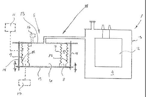
Figure 1 shows schematically the basic structure of the invention
and how the present invention operates in connection with a subsea installa-
tion. In the example of Figure 1 the subsea installation is a subsea
transformer.
Reference number 1 shows generally the subsea transformer. The subsea
transformer 1 comprises the transformer unit 2 and a tank 3. The tank is
filled
with insulation medium, i.e. in this case transformer oil. The tank 3 forms an
in-
sulation chamber around the transformer unit 2.
In order to compensate volume variations of the insulating medium
4 there is a pressure compensator 5. The pressure compensator 5 comprises
a first bellows chamber 6. The first bellows chamber 6 comprises a first bel-
lows part 7. The first bellows part 7 is made of a suitable material, for
example
of steel.
The first bellows chamber 6 is through a pipe or channel system 18
in flow connection with the insulation chamber formed by the tank 3 so that
said bellows chamber 6 can compensate volume variations of the insulating
medium 4.
The assembly shown in Figure 1 is wholly surrounded with sea wa-
ter, i.e. the assembly is placed on the bottom of the sea.
The matters above are widely known in the fields and therefore said
matters are not described here in detail.
As told before the problems in prior art solutions relate to corrosion
damages in the bellows part of the pressure compensator, ie. sea water
causes corrosion problems in the first bellows part.
CA 02738056 2013-11-29
According to the basic idea of the invention the first bellows cham-
ber 6 is surrounded by a second bellows chamber 8 comprising a second bel-
lows part 9. The second bellows chamber 8 is configured to form a closed in-
termediate space around the first bellows chamber. The walls of the second
5 bellows chamber are configured to separate at least the bellows parts 7 of
the
first bellows chamber 6 from the surrounding sea water. The second bellows
chamber 8 is further filled with an intermediate medium 10. The second bel-
lows part 9 of the second bellows chamber 8 is preferably made of a material
resistant to surrounding sea water.
In other words the expansive and compressive element of the pres-
sure compensator has two barriers or walls between transformer related space
and seawater.
The inner barrier, i.e. the first bellows part 7 is made of metallic bel-
lows construction and the outer barrier, i.e. the second bellows part 9 is
made
of rubber material or rubber like material. Said rubber like material can be
for
example appropriate plastic material or a mixture with rubber material and
plastic material. The space between the first bellows part 7 and the second
bellows part 9, i.e. the second bellows chamber 8 is filled with the same
trans-
former oil or oil which is mixable with the transformer oil 4 in the first
bellows
chamber 6 and in the tank 3. There is however no exchange of oil through the
first bellows part 7.
The second bellows part 9 made of rubber material or like protects
the first bellows part 7 made of metal material from corrosion. In this connec-
tion it is important to realise that the first bellows part 7 due to
flexibility needed
must have a typically thin wall construction, and therefore corrosion matters
are very important as regards the operation of the device. The typical wall
thickness of the first bellows part 7 is in 1 mm scale. In order to have more
flexibility and reliability the first bellows part 7 can be constructed also
with one
or more metallic layers.
The small volume changes of the closed intermediate oil space, i.e.
the second bellows chamber 8 between the first and the second bellows parts
must also be compensated. This is carried out e.g. by making the second bel-
lows part 9 so that it is able also to expand in radial direction due to
pressure
variation or by using an additional small pressure compensator 11 connected
to the intermediate space, i.e. to the second d bellows chamber 8. Said even-
CA 02738056 2013-11-29
6
tual additional small compensator can have one barrier construction without
loosing the double barrier feature of the whole pressure compensator.
The rubber material used in the second bellows part 9 can be for
example Nitrile rubber, which is resistant against sea water and after
suitable
treatment compatible wit the transformer oil too.
The second bellows part 9 can be made wholly of said rubber or
rubber like material. It is however quite possible to put appropriate
strengthen-
ing material or several strengthening materials to the bellows part material,
for
example inside of the bellows wall as shown with a reference number 12 in
Figure 1.
In this connection it is however important to realize that it is quite
possible instead of the rubber material bellows to use the second bellows part
9 made of steel material. The steel material used can for example be selected
so that it is as resistant as possible against sea water. Said second bellows
part 9 made of steel also protects efficiently the first bellows part 7
against cor-
rosion caused by sea water before the second bellows part is through cor-
roded. The pressure compensator can however be changed before the first
bellows is corroded.
The other walls of the pressure compensator, which are not chang-
ing their shape and size, for example end walls 13 of the tubular form bellows
parts can be made for example of thick enough one layer metallic material,
like
e.g. stainless steel plates. Said walls can however be for example two-layer
construction like rubber material/metal material walls.
The pressure compensator of the invention can also be provided
with guiding rods 14 for guiding the first and the second bellows parts to
move
during compression and/or expansion along defined paths. Said compression
and expansion movements of the bellows parts are shown by arrows in Figure
1. The number of said guiding rods can be chose freely according to the exist-
ing need. It is quite possible for example to materialize the pressure compen-
sator without said guiding rods. Figure 2 shows an embodiment of the inven-
tion with four guiding rods 14 and Figure 3 shows another embodiment of the
invention with two guiding rods 14. In the embodiments of Figures 1 ¨ 3 the
guiding rods 14 are located circumferentially outside the bellows parts. Said
placement is however not the only possibility but said guiding rods 14 can
also
be place in the bellows parts. Said embodiments are shown in Figures 4 and 5
in which one guiding rod is used and said guiding rod 14 is placed centrally
in
CA 02738056 2013-11-29
7
the bellows parts. The end plates 13 are also materialized differently in the
embodiments of Figures 4 and 5 when compared to the embodiments of Fig-
ures 1 ¨ 3. In the embodiments of Figures 4 and 5 the first bellows part 7 and
the second bellows part 9 have both at one end thereof an end plate of its
own, and use a common end plate at the other ends thereof.
The guiding rods 14 of the pressure compensator are connected
movable with guiding bushings 15 around the guiding rods to the movable
parts of the pressure compensator. The material of the guiding bushings 15 is
selected so that the bushings do not easily jam and so that moving bushings
will keep the surfaces of the guiding rods clean from marine fouling and other
eventual impurities, which might cause jamming. Any appropriate material can
be used for the guiding bushings 15, for example several plastic materials are
suitable. As an example of particularly materials nylon can be mentioned. Fig-
ure 6 shows an example how said guiding bushings 15 can be materialized for
example in the embodiments shown for example in Figures 2 and 3. Said guid-
ing bushings can be made as replaceable parts.
The guiding bushings 15 of the guiding rods can however be made
so that if these should however jam the bushings will break due to compres-
sion and expansion movement forces and said breaking will release the jam-
ming. After that the wider metallic part of the bushing will guide the move-
ments. Nylon is suitable material to have this breaking feature too.
The guiding rods and the related bushings can also be formed so
that they can also be used as indicators of the pressure compensator opera-
tion state as indicating the bushing position, i.e. the guiding rod
arrangement
can also act as an indicator of the movements of the bellows parts. The bush-
ing position can be inspected by any appropriate ROV (Remote Operate Vehi-
cle) camera when the rods are on the outer surface of the outer expanding and
compressing barrier.
The number of the pressure compensators connected parallel to the
subsea installation, for example to the subsea transformer or to some other
possible object to be compensated, is selected so that the total oil volume re-
quired can be compensated.
The pressure compensator can also include electrically based cor-
rosion protection means or some other type of corrosion protection means.
Said corrosion protection means can be situated also inside the pressure com-
CA 02738056 2013-11-29
8
pensator to protect the first bellows part made of metal material. Reference
number 16 in Figure 1 shows schematically said corrosion protection means.
The pressure compensator of the invention can also be provided
with monitor means for monitoring the amount of sea water eventually leaked
into the intermediate space, i.e. into the second bellows chamber 8. Reference
number 17 in Figure 1 shows said monitoring means.
As discussed above the number of the pressure compensators used
in connection with a subsea installation can vary according to the existing
need. Typical compensation volume of the pressure compensators required in
near future big subsea transformers in hundreds of litres, for example 200
litres, and typical number of compensators needed in one big subsea trans-
former is from 2 to 6 compensator units. As an example Fig. 7 shows a subsea
transformer with four pressure compensators.
The embodiments described above are not intended to restrict the
invention but only to clarify the basic idea of the invention. It is quite
clear that
details can be varied freely without departing from the scope of the
invention.
The invention is described here in connection with subsea transformers. The
invention is however not restricted solely to subsea transformers but the
inven-
tion can also be used in connection with all subsea installations using insula-
tion medium and needing compensation of said insulation medium etc. Insula-
tion medium need not be transformer oil but any other medium or fluid can be
used according to the existing need.
The scope of the claims should not be limited by the preferred
embodiments set forth in the examples, but should be given the broadest
interpretation consistent with the description as a whole.