Note: Descriptions are shown in the official language in which they were submitted.
CA 02738344 2011-03-24
WO 2010/034123
PCT/CA2009/001361
Dual Vessel Reactor
Field of the Invention
The invention relates to a reactor for high pressure and high temperature
reactions
and more specifically to a dual vessel reactor.
Background
Many reactions require high temperatures and pressures to take place and are
therefore carried out in a reactor. As a result, reactors typically have an
outer
pressure vessel for withstanding the pressure in the reactor. A dual vessel
reactor
has an inner vessel in which the reaction may be carried out. The inner vessel
is
heated to a reaction temperature either by an external source or by the
reaction itself.
The outer vessel is typically a pressure vessel and has a relatively large
thickness as
compared to the inner vessel wall so that the reactor can handle elevated
reaction
pressures.
Some chemical reactions, for example, the devulcanization of rubber, require
temperatures as high as 350 C. As a result, a door in the outer vessel
requires that
a metal ring be used to seal the door with the reactor when in the closed
position. A
rubber seal cannot be used as the high temperatures of the reactor and
specifically
the outer vessel damage the seal and can cause failure of the seal which is
costly
and creates safety issues when the pressure can no longer be contained.
Metal seals, such as metal American Petroleum Institute (API) rings, are
costly, can
only be used once, and therefore drive up the cost of running a reaction in a
reactor.
Furthermore, reactors having outer vessels that experience higher operating
temperatures, experience higher rates of corrosion on the metals used in the
outer
vessel and therefore require the use of costly metals such as stainless steel
or other
equivalent costly alloys in fabrication. Any increase in temperature of the
outer
vessel increases the corrosion rate. Furthermore, conventional coatings, such
as
paints, that can be used to protect steel at elevated temperatures are
difficult to find.
Water cooling the seal is a possibility, and water cooled seals are available.
However
water cooling the large metal flange which houses the seal will result in the
flange
operating at lower temperatures and as a consequence will cause a substantial
amount of condensation onto it, and heat transfer to it. Ignoring for a minute
the costs
associated with this heat loss, such a loss of heat will ultimately limit the
operating
- 1 -
CA 02738344 2011-03-24
WO 2010/034123
PCT/CA2009/001361
temperature of the reactor, that is, the heat that is being added to heat the
vessel is
being lost through condensation on the flange. As a result, water cooling the
seal is
undesirable.
A need therefore exists for a dual vessel reactor for use in reactions having
a high
reaction temperature, having an outer vessel suitable for operation with a non-
metal
seal and a method of carrying out a reaction in a reactor wherein the outer
vessel of
the reactor does not exceed an operating temperature of a non-metal seal or
has an
operating temperature lower than the reaction temperature.
Summary
In one illustrative embodiment there is provided a dual vessel chemical
reactor
comprising:
an outer vessel;
a reactor lid on the outer vessel, the reactor lid openable for accessing
the inner vessel;
an inner vessel within the outer vessel for containing a liquid, the inner
vessel in atmospheric communication with the outer vessel;
a heat source for heating a liquid in the inner vessel;
a seal for sealing the reactor lid with the outer vessel when in a closed
position;
an inner vessel lid for covering the inner vessel;
wherein during operation a non-condensable gas is used to
substantially insolate the outer vessel from the inner vessel.
In another illustrative embodiment, the reactor as described above further
comprises:
a non-condensable gas input for inputting the non-condensable gas into the
outer vessel.
In another illustrative embodiment there is provided a method of maintaining
an outer
vessel at a temperature below a reaction temperature while carrying out a
reaction in
a dual vessel chemical reactor, the dual vessel chemical reactor having an
inner
vessel in atmospheric communication with the outer vessel and substantially
partitionable from the outer vessel. The method comprises the steps of: adding
a
non-condensable gas to the reactor; heating a liquid in the inner vessel to
generate a
vapour; and substantially partitioning the non-condensable gas in the outer
vessel
and the vapour in the inner vessel.
- 2 -
CA 02738344 2011-03-24
WO 2010/034123
PCT/CA2009/001361
In another illustrative embodiment there is provided a method of carrying out
a
chemical reaction in a dual vessel chemical reactor, the dual vessel chemical
reactor
having an inner vessel in atmospheric communication with the outer vessel and
substantially partitionable from the outer vessel. The method comprises the
steps of
adding a non-condensable gas to the reactor; adding a reactant to a liquid in
the
inner vessel; heating the liquid in the inner vessel to generate a vapour; and
substantially partitioning the non-condensable gas in the outer vessel and the
vapour
in the inner vessel.
Brief Description of the Drawings
Figure 1 is a schematic of a prior art reactor wherein the outer vessel has an
operating temperature exceeding that of the operating temperature of a rubber
seal;
Figure 2 is an illustrative schematic of one embodiment of a dual vessel
chemical
reactor; and
Figure 3 is a graph illustrating test results for operating an embodiment of
the reactor
at various starting pressures of non-condensable gas over a range of
temperatures;
Figure 4 depicts in a schematic a cross sectional view of an illustrative
inner vessel
for use in a dual vessel reactor;
Figure 5 depicts in a schematic a cross sectional view taken along the line A-
A' in
Figure 4;
Figure 6 depicts in a schematic a view taken along the line B-B' in Figure 4;
Figure 7 depicts in a flow chart an illustrative method of maintaining an
outer vessel
at a temperature below a reaction temperature; and
Figure 8 depicts in a flow chart an illustrative method of maintaining an
outer vessel
at a temperature below a reaction temperature.
Detailed Description
A dual vessel reactor and a method of carrying out a reaction using a dual
vessel
reactor are provided using a non-condensable gas to substantially isolate the
inner
vessel from the outer vessel during the reaction and limit the heating of the
outer
vessel when steam from the inner vessel condenses on the interior surface of
the
- 3 -
1
CA 02738344 2011-03-24
WO 2010/034123
PCT/CA2009/001361
outer vessel. By limiting the heating of the outer vessel through the
condensation of
the steam or other vapour from the inner vessel, the operating temperature of
the
outer vessel is kept below an upper threshold of the operating temperature of
a non-
metallic seal such as a rubber seal used to seal the door in the outer vessel.
The
lower outer vessel temperature also reduces corrosion and allows for more
conventional coatings, such as paints, to be used to protect the metal.
A prior art dual vessel reactor is shown in Figure 1 in which a reactor 5 is
shown
having an inner vessel 10 within an outer vessel 20. The reactor 5 has a
reactor lid
60 sealed to the outer vessel 20 using a metal API ring 70. A nitrogen
environment
25 is established in the reactor 5. A heater 30 heats a liquid in the inner
vessel 10
into which a reaction container may be placed. Heating of the inner vessel 10
and
the inner vessel liquid 15 results in elevated temperature of the outer vessel
20 (for
example it will rise in temperature until it is at the operating temperature
of the inner
vessel) and the necessity of a metal seal, such as the metal API seal 70.
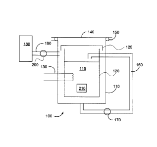
Figure 2 is an illustrative schematic of one embodiment of a dual vessel
chemical
reactor 100 wherein during operation a non-condensable gas is used to isolate
an
inner vessel 120 from an outer vessel 110. This isolation resulting in the
cooling of
the outer vessel 110 will be explained in more detail below.
The chemical reactor 100 has an inner vessel 120 for containing a liquid 115.
The
liquid 115 may be one of a reaction solvent for either dissolving a reactant
or
suspending a reactant, a solution for providing heat transfer to a reaction
container
210 upon heating of the solution, or may be a reactant in liquid phase for
reacting
with a reactant in suspension or in a reaction container 210. The liquid may
be water
which forms steam upon heating or another liquid that forms vapour upon
heating.
The liquid 115 may be any organic or inorganic liquid, preferably with a
boiling point
above about 25 C. For the purposes of this disclosure, the term steam will be
used
to encompass both water steam and liquid vapour.
An outer vessel 110 encapsulates the inner vessel 120 and together with a
reactor lid
140 form the pressure vessel for the chemical reactor 100. The outer vessel is
typically made of a corrosion resistant alloy of a suitable thickness to
withstand
reaction pressures experienced during a chemical reaction to be carried out in
the
reactor 100. The outer vessel may be made from coated steel to resist
corrosion and
does not have to be made from costly stainless steel. For example, the outer
vessel
110 may be made Monel , Inconel0 or Haste'lop. Some coatings for the outer
- 4 -
CA 02738344 2011-03-24
WO 2010/034123
PCT/CA2009/001361
vessel 110 may include plasma, thermal coatings or weld cladding. The reactor
lid
140 may be an automatic lid or a manually operated lid sealed to the outer
vessel
110 when in a closed position by a seal 150. The seal 150 may be for example,
but
not limited, to a rubber o-ring or the like. As will be appreciated in the
art, the use of
o-rings depends on the temperature and the chemicals to which they will be
exposed.
For steam and temperatures below 200 C o-rings made from ethylene propylene
diene M-class rubber (EPDM), silicone rubber, KaVex , polyacrylate, Viton ,
flurosilicone or Aflaf TM are available. The options become even wider if the
outer
vessel 110 is kept below 100 C throughout the reaction. If necessary, the
outer
vessel 110 may be cooled so it does not go above a predetermined temperature.
This additional cooling may be done for example, but not limited to by air or
water
cooling.
An inner vessel lid 125 covers the inner vessel 120 but does not hermetically
seal the
inner vessel 120 from the outer vessel 110. When the lid 125 is in place, the
inner
vessel 120 is not sealed from the outer vessel and the pressure between the
inner
vessel 120 and the space between the inner vessel 120 and the outer vessel 110
is
equilibrated. The lid 125 may have one or more holes, or valves, for example
but not
limited to flapper valves or the like that allow the pressure in the inner
vessel 120 and
the pressure between the inner vessel 120 and the outer vessel 110 to
equilibrate.
Such a setup also prevents or minimizes any damage to the inner vessel 120 if
the
pressure in it is changed quickly (i.e. the steam is vented). The holes or
valves allow
pressure between the inner vessel 120 and the outer vessel 110 to equilibrate
throughout the reaction.
A heat source 130 is used to heat the liquid 115 in the inner vessel 120. The
heat
source 130 may be any suitable heat source suitable for heating liquid in a
reactor.
For example, a flanged over-the-side immersion heater may be used or a band
heater may be used which heats the outside of the inner vessel 120.
Alternatively,
external heating of the liquid 115 may be carried out using for circulation
heaters
where the liquid 115 is pumped out of the reactor 100, heated externally (by
electricity, gas, etc.), and then pumped back into the inner vessel 120.
Alternatively,
a vapour injector for injecting heated vapour may used as described in co-
pending
Canadian patent application 2,582,815 which is incorporated herein by
reference.
As will be discussed in more detail below, steam from the liquid 115 in the
inner
vessel 120 condenses on the outer vessel 110 during a reaction cooling the
outer
- 5 -
CA 02738344 2011-03-24
WO 2010/034123
PCT/CA2009/001361
vessel 110. An optional pump 170 may be used to re-circulate liquid that
condenses
on the walls of the outer vessel 110 using piping 160.
The reactor 100 uses a non-condensable gas between the vessels 110 and 120 to
limit the condensation of steam onto the inside wall of the outer vessel 110
and
thereby limit the heating of the outer vessel 110 by the steam and negate the
increase in the operating pressure of the reactor by the addition of the non-
condensable gas. Non-condensable gases are gases that will not condense on the
walls of the outer vessel 110 under the operating conditions (temperature and
pressure) of the reactor 100. They may be supplied as compressed gas at room
temperature and include for example both inert and non-inert gases and include
oxygen, nitrogen, air, argon, methane, ethane, ethylene, hydrogen, helium,
carbon
monoxide, nitric oxide, nitrous oxide, and combinations thereof, etc. To
achieve this,
the non-condensable gas is substantially partitioned during operation into the
space
between the inner 120 and outer vessels 110 and the steam is partitioned into
the
inner vessel 120, thereby reducing or negating the effects of Dalton's Law. A
comparative example will be used to illustrate these effects as well as the
partitioning
of the non-condensable gas from the steam and the operation of the reactor
100.
The inner vessel 120 may be constructed of any suitable material such as
corrosion
resistant alloys and alloys having a corrosion resistant coating. Exotic
alloys may be
used in the construction of the inner vessel 120 as the inner vessel 120 is
much
thinner than the outer vessel 110 and is therefore less expensive to
fabricate. A non-
limiting example of alloys that may be used in fabricating the inner vessel
are
stainless steel, Inconel , Monel , hastealloy, etc.
Comparative Example
The following comparative example is illustrative and the Applicant does not
wish to
be bound by theory.
A schematic of a dual reactor that does not partition the non-condensable gas
is
shown in Figure 1. The dual reactor 5 does not have a cover and is used to
illustrate
one of the problems that has been overcome with the dual vessel reactor and
method of carrying out a reaction as described herein with references to
Figures 2
and 3. The reactor 5 has water in the inner reactor and the remainder of the
space is
filled by pressurized nitrogen. For example, the nitrogen has been set at a
pressure
that will create a partial pressure of 150 psi (1034 kpa) when the water has
been
- 6 -
1
CA 02738344 2011-03-24
WO 2010/034123
PCT/CA2009/001361
heated to a certain temperature (for example 180 C). When the water is heated
to
this temperature, the steam creates a partial pressure of water of 150 psi
(1034 kpa).
Using Dalton's Law the pressure in the vessel would then be 300 psi (2068
kpa). It
can be seen from this example that it is not desirable to add nitrogen or
other non-
condensable gases, to the vessel as it increases the operating pressure of the
vessel
and thus the cost of the vessel as higher operating pressures require thicker
metal in
construction of the outer pressure vessel.
In a reactor such as that described herein, for example with reference to
Figure 2,
non-condensable gas, such as nitrogen, is added to the reactor in Figure 2 via
for
example an input 200 from a non-condensable gas reservoir 180, for example
through the use of a valve 190. It will be appreciated that the non-
condensable gas
may be added to the reactor 100 using any suitable method and the reactor
design is
not limited to the method or apparatus for inputting the non-condensable gas.
The
non-condensable gas may be introduced through a series of valves (which may or
may not be computer controlled), with pressure gauges to monitor their
pressure.
Introducing the non-condensable gas by computer control is the preferable
method
when introducing the non-condensable gas during the reaction. The non-
condensable gas is added, for example, so that it will generate a pressure of
approximately 150 psi (1034 kpa) when the nitrogen has been substantially
partitioned in the space between the inner vessel 120 and the outer vessel
110. As
the liquid 115 is heated in the inner vessel 120 to a point where the steam
generates
a pressure of 150 psi (1034 kpa) it builds up a pressure of steam in the inner
vessel
120 and this pushes the non-condensable gas from the inner vessel 120 to the
space
between the vessels 120 and 110 (i.e. the steam substantially partitions the
non-
condensable gas into the space between the inner vessel 120 and the outer
vessel
110 and the steam into the inner vessel 120). The partitioning process is a
dynamic
process. As the liquid is heated, and steam is generated, a mixture of non-
condensable gas and steam flow out of the inner vessel 120 into the space
between
the inner 120 and outer vessel 110. However, because the walls of the outer
vessel
110 are cooler than the steam, the steam condenses on them. When the steam
condenses it reduces the pressure between the inner 120 and outer vessels 110
and
this causes even more steam and nitrogen to flow out of the inner vessel 120.
In this
way the steam that enters the space between the inner 120 and outer 120
vessels
continues to condense on the cooler walls of the outer reactor and eventually
drives
most of the non-condensable gas into the space between the inner 120 and outer
110 vessels partitioning the steam into the inner vessel 120 and the non-
- 7 -
CA 02738344 2013-12-23 ,
, .
condensable gas into the space between the two vessels 110 and 120. The non-
condensable gas in the space between the inner 120 and outer 110 vessels then
acts as an insulator between the inner 120 and outer 110 vessels limiting heat
transfer and maintains the outer vessel 110 cooler than the inner vessel 120
without
steam continuously condensing on it as in Figure 1. A situation is achieved
where
the pressure in the space between the inner 120 and outer 110 vessels is about
150
psi (1034 kpa) (mainly from non-condensable gas) and an equal pressure is
observed inside the inner vessel 120 (mainly from steam).
If necessary, the outer vessel 110 may be cooled using an external cooling
device.
Figure 4 depicts in a schematic an inner vessel 400 that may be used as the
inner
vessel 120 of a reactor as described above. Figures 5 and 6 depict in
schematics
cross sections of the inner vessel 400 taken along lines A-A' and B-B'
respectively.
The inner vessel 400 has an outer shell 402 and an inner shell 404. The inner
shell
404 is covered by a cover 406. The inner shell 404 is not sealed by the cover
406,
and liquid is able to freely pass between the inner shell 404 and the outer
shell 402.
The inner shell 404 provides a container where reactions may take place.
The outer shell 402 is covered with a lid 408. The lid 408 has a collar 409
that seals
the interior of the inner vessel 400; however, the lid 408 also includes
passageways
412 that allow vapour, non-condensable gas, or a combination of the two to
pass
between the interior of the inner vessel 400 and the exterior of the inner
vessel. The
passageways 412 allow the interior of the inner vessel to be at a similar
pressure as
the interior of the outer vessel, which it is enclosed in.
The inner vessel includes a plurality of ports 410, 414, 416. Ports 410 may be
used
to exhaust vapour or steam from the interior of the inner vessel 400 once the
reaction
is completed. This exhaust may be used, for example, to preheat other
reactions
occurring in other reactors. Exhausting the vapour through ports 410 helps to
cool
down the inner vessel 400 once the reaction is completed. Ports 414 may be
used
as inlet ports to fill the inner vessel with the required liquid and possibly
any other
reactants, required for the reactions. Port 416 may be used as an outlet for
emptying
the liquid from the interior of the inner vessel. The port 416 may also be
used to
circulate, and possibly heat, the liquid in the interior of the inner vessel
400. The
liquid could, for example, be circulated from the port 416 and input back into
the inner
vessel 400 via one of the ports 414.
- 8 -
CA 02738344 2013-12-23
A heater 418 comprising a plurality of heating elements 420 is suspended in
the inner
shell 404. The heater 418 is fixed to a flange 422 on the outer shell 402. The
heater
418 may be fixed to the flange using, for example, bolts. The flange 422
allows an
electrical wire 424 to pass through the outer shell 402, while maintaining the
integrity
of the outer shell 402.
The inner vessel 400 may be seated on a bottom surface of the outer vessel,
depicted as 428 in Figure 4. The inner vessel may be raised off of the bottom
surface 428 by a supporting structure, such as for example, support legs 426.
Figure 7 depicts in a flow chart a method 700 of maintaining an outer vessel
at a
temperature below a reaction temperature. The method may be used to maintain
the
temperature of the outer vessel while carrying out a reaction in a dual vessel
chemical reactor. The method begins with adding a non-condensable gas to the
dual
vessel reactor (702). The amount of non-condensable gas added may vary
depending on the type of control used during the reaction. For example, a
final
amount of non-condensable gas may be added at the start, in which case further
non-condensable case does not need to be added during the reaction.
Alternatively
a lower amount of non condensable gas may be added initially, and additional
non
condensable gas added during the reaction process. Regardless of the type of
control used, an initial amount of non-condensable gas is added to the dual
vessel
reactor. With the non-condensable gas added, the liquid in the inner vessel is
heated
(704). The heating of the liquid brings the liquid temperature up to a
reaction
temperature. Vapour is formed from the heated liquid. The non-condensable gas
and vapour is partitioned so that the vapour is substantially partitioned
inside the
inner vessel (706). This partitioning of the vapour to the interior of the
inner vessel
prevents vapour from condensing on the wall of the outer vessel, which would
raise
the temperature of the outer vessel.
The vapour is partitioned as a result of the non-condensable gas. The partial
pressure of the non-condensable gas is maintained above the partial pressure
of the
vapour, which in combination with the passageways between the inner and outer
vessels restricts the vapour from escaping the interior of the inner vessel.
Figure 8 depicts in a flow chart, a method 800 similar to method 700; however,
the
method 800 further comprises monitoring the temperature of the reaction to
maintain
a pressure differential between the non-condensable gas and the vapour. The
method begins with adding an initial amount of non-condensable gas to the dual
- 9 -
CA 02738344 2011-03-24
WO 2010/034123
PCT/CA2009/001361
vessel reactor (802) and then heating the liquid (804) up to a reaction
temperature.
The method monitors the liquid temperature (806) and determines if the
reaction is
complete (808). If the reaction is complete (Yes at 808) the method ends. If
the
reaction is not complete (No at 808), the method determines a vapour partial
pressure (Pv) that results from the liquid temperature (810). The method then
determines if the partial pressure of the non-condensable gas (Pnc) is less
than or
equal to Pv plus a pressure differential (Apres) that is to be maintained
(812). If it is
less than or equal to (Yes at 812) then more non-condensable gas is added to
the
dual vessel reactor (814) to restore the desired pressure differential. The
method
then returns to monitor the temperature of the liquid (806). If Pnc > PV +
Aprõ (No at
812) the method returns to monitor the temperature of the liquid (806).
It will be appreciated that the above methods may be used to carry out various
chemical reactions. The inner vessel may hold solid or large reactants, while
further
reactants may be added to the liquid that is heated.
Experimental Examples
A series of experiments have been performed validating the concept outlined
above
using a non-condensable gas in the space between the two vessels 110 and 120
thereby allowing the outer vessel 110 of the reactor 100 to run at a
temperature that
is much cooler than the inner vessel 120. The results of the experiments are
shown
in Figure 3.
In the experiments, a pressure vessel (outer vessel 110) was used that is 36
inches
diameter and 10 ft long, and rated at 150 psi (1034 kpa). It has an inner
vessel 120
that can hold approximately 800 L of liquid (in this case water). The water is
heated
with an immersion heater 130. Any open spaces between the inner 120 and outer
110 vessels were minimized and two flapper valves installed in the lid 140 to
allow
the pressure to equilibrate between the vessels 110 and 120.
In the series of experiments water was heated in the inner vessel 120 from 25
C to
180 C and held there for 1 hour. Preset pressures of nitrogen were used (e.g.
40
psi (276 kpa) at 25 C) and the temperature of the water and pressure was
monitored
in the vessel 120 as the water was heated to 180 C. The results are shown in
Figure
3 along with the vapour pressure curve for water.
- 10 -
CA 02738344 2011-03-24
WO 2010/034123
PCT/CA2009/001361
It can be seen that the curves for the experiments with starting pressures up
to 60 psi
(414 kpa) merge with the curve for water but that the curve for the starting
pressure
of 95 psi (655 kpa) does not merge and is much higher.
The experimental data has been supplemented with computer modeling. For the
experimental set up (i.e. volumes of the inner 120 and outer 110 vessels that
contain
non-condensable gas, etc) there is a cross over point. That is, at a starting
pressure
of about 70 psi (483 kpa) of non-condensable gas such as nitrogen, and at the
end
point, that is 180 C, all the nitrogen that is in the inner vessel 120 has
been purged
out of the inner vessel 120 and the pressure of nitrogen in the space between
the
inner 120 and outer 110 vessels (which now contains the nitrogen that was
originally
in this space plus the nitrogen purged from the inner reactor) equals the
pressure of
the steam in the inner vessel 120. That is the steam and the nitrogen has been
partitioned.
It must be stressed that even though the reactor was started with a pressure
of 70
psi (483 kpa) of nitrogen, the final pressure was 150 psi (1034 kpa), which is
also the
saturated vapour pressure of the water at 180 C, and this means that there was
no
nitrogen left in the inner vessel otherwise (through Dalton's Law) the
pressure would
have been higher.
For non-condensable gas starting pressures above 70 psi (483 kpa), it is not
possible
to purge all of the non-condensable gas out of the inner vessel 120 because it
would
result in a pressure between the vessels 110 and 120 that exceeds the steam
pressure in the inner vessel 120. Part of this "surplus" remains in the inner
vessel
120 and results in pressures that exceed the vapour pressure of water (see 95
psi
(655 kpa) curve).
For non-condensable gas starting pressures below 70 psi (483 kpa), there is
not
sufficient non-condensable gas to fill the space between the two vessels 110
and 120
with non-condensable gas at 150 psi (1034 kpa) when the water is heated to 180
C
and there is what will be referred to as a "deficit" in non-condensable gas in
the
space between the vessels 110 and 120. This deficit is taken up by steam which
can
condense on the walls of the outer vessel 110 if the walls are cooler than the
steam
temperature. The bigger the deficit, the larger the heat flow to the outer
reactor will
be as steam condenses on it. For example, during the course of the experiment
an
additional 25 L of water condensed on the walls when the starting pressure was
8 psi
(55 kpa) versus 60 psi (414 kpa).
-11-
CA 02738344 2011-03-24
WO 2010/034123
PCT/CA2009/001361
Therefore, for the experiments used above, a useful starting pressure is about
70 psi
(483 kpa). Under these conditions, and without any cooling to the outer vessel
110,
the temperature rise of the vessel 110 was limited to 40 C versus 155 C if
the non-
condensable gas had not been there.
Even though the procedure described above limited the temperature rise to
about 40
C most of the heating that occurred came from the fact that steam is also
purged out
of the inner vessel 120 along with the non-condensable gas. This can be
minimized
further by adding the non-condensable gas as the water is actually being
heated (not
before the experiment) so that, for example, a surplus pressure of non-
condensable
gas of 10 psi (69 kpa) is maintained (i.e. 10 psi (69 kpa) over the equivalent
steam
pressure), and it is not therefore necessary to purge the non-condensable gas
out of
the inner vessel 120 as the water is heated.
Illustrative Processes for Carrying out a Reaction
Taking a broader look at the process, some options for adding the non-
condensable
gas are but are not limited to:
1. Start with 150 psi (1034 kpa) and vent gas as the pressure rises.
2. Start with pressures ideally around the cross-over point.
3. To add non-condensable gas as the liquid is heated to maintain an excess
pressure (over that of steam).
In options 1 and 2 the non-condensable gas is added and the vapour pushes it
out of
the inner vessel 120 into the space between the inner vessel 120 and the outer
vessel 110. The process of pushing the non-condensable gas out of the inner
vessel
120 also results in the transfer of steam into the space between the vessel
110 and
120 followed by the condensation of the steam onto the outer vessel 110. In
option 3
this transfer is limited by adding the non-condensable gas as it is needed. A
small
pressure (for example 10 psi) of the non-condensable gas is used at the start
of the
process in the reactor 100. As the liquid 115 is heated and the pressure of
the steam
in the inner reactor rises, non-condensable gas is added to the space between
the
vessels 110 and 120 to maintain a pressure that is above the pressure of the
steam
in the inner vessel 120. For example, the excess pressure may be 10 psi. In
this
way, the non-condensable gas is purged out of the inner vessel 120 and heat
transfer from the steam that accompanies it is minimized. The 10 psi is an
example
- 12 -
CA 02738344 2013-03-14
of what could be used for lower pressure reactions (for example up to 150 psi)
DUI
this pressure could be much higher for operations at higher pressures. It will
be
appreciated that the vapour pressure of the liquid 115 may be determined by
measuring its temperature as it is being heated and computing its vapour
pressure.
in terms of how well the inner vessel 120 is sealed, originally half inch of
space
around the immersion heater flange was provided. This resulted in an open
space
(to the outer vessel 110) of about 14 in2 (90 cm2). Under equivalent test
conditions
this open space caused an additional 12 L of water to condense during the
experiment mentioned above.
Although the examples above use a pressure of 150 psi, the reactor 100 may
operate at much higher pressures of 500 psi or 1000 psi as necessary for
carrying
out a specific reaction. The concept of partitioning the non-condensable gas
from the
steam for cooling the outer vessel 110 applies at high pressures as well and
the
examples above are merely illustrative and not limiting. The thickness of the
pressure vessel increases as the pressure increases. Reaction pressures of up
to
2,000 psi may be carried out in a reactor as described herein.
The devulcanization of rubber may be carried out in a reactor as described
herein at
a reaction pressure of not over 2000 psi and a reaction temperature of not
over 350
C. The outer vessel 110 is kept cool by minimizing thermal contact between the
two
vessels 110 and 120 and by insulating the inner vessel 120 from the outer
vessel 110
using the partitioned non-condensable gas and the vapour as described above.
Some heat transfer through the non-condensable gas between the vessels 110 and
120 is observed, and of course any steam that condenses on the outer vessel
110
transfers heat. The condensation of steam can be reduced by introducing the
non-
condensable gas during the reaction and maintaining an excess pressure of the
non-
condensable gas over the steam as outlined in option 3 above. In one
embodiment,
the non-condensable gas is introduced by computer control.
The present invention has been described with regard to a plurality of
illustrative
embodiments. However, it will be apparent to persons skilled in the art that a
number
of variations and modifications can be made without departing from the
teachings
of the description.
- 13 -