Note: Descriptions are shown in the official language in which they were submitted.
CA 02738713 2011-03-28
ROLL STAND
The invention concerns a roll stand with at least one
upper and one lower roll supported by respective backing rolls
mounted on a common roll frame and in bearings that are vertically
displaceable with respect to each other for setting different roll
gaps, with at least one axial shifter for one of the rolls and with
at least one bender comprising a bending cylinder for bending the
upper roll.
Roll stands of this type can have especially several
backing rolls above and below the roll gap, for instance, one work
roll that comes in direct contact with the rolling stock and in
turn rolls on a usually larger backing roll or an intermediate
roll, which in turn abuts another backing roll. The work rolls
and/or the backing rolls and/or the intermediate rolls can be
displaceable axially relative to each other. This way as a result
of the shape of the surface of at least two rolls, targeted effects
are possible with respect to the shape of the rolling stock running
through the roll gap. The height of the roll gap is thereby
intended to be adjustable, which requires a vertical displacement
at the frame.
it is particularly difficult when in addition to the
axial shifter, a work-roll bender is provided, even for a large
roll intake, i.e. at large height of the roll gap, to guarantee the
ability to set it. This is because in the bender, which is
intended to counter-act a bending apart of the rolls that define
the gap for the rolling stock, integrated locking elements as well
- 1 -
CA 02738713 2011-03-28
as the guide elements for the axial shifter and the bearings for
the rolls in the lateral beams of the stand, must be displaced and
selected .
A roll stand is known from EP 1 436 104 [US 7,310,985]
with at least one axial shifter that makes it possible to set a
large roll gap for rolling of thick blocks or slabs. In the known
solution, the axial shifter is integrated into the construction
components that retain the bearings for a work roll, so that a
separate vertical displaceability of the axial shifter is no longer
required.
The axial displacement of the work rolls is done by a
shifter mounted coaxially on an insert of the work roll that is
backed out of the frame with the set of rolls during a change of
the work roll. In so-called "flying" work-roll bending, the upper
work-roll inserts are supported by bending or balancing cylinders
in U-shaped recesses of the upper backing-roll inserts. The
bending cylinders can be located in the work-roll inserts or
alternatively in the backing-roll inserts.
With a "flying" arrangement of the upper work roll, a
very tall roll gap is conceivable. This would also make the
rolling of thick blocks possible on such a roll stand. The work
roll displacement and benders are backed out of the roll frame
during a change of the set of rolls and can be maintained outside
the roll frame. As a result, the operator does not have down time
of the system while maintaining these units.
During axial displacement of the work roll, the upper
work-roll assembly is pushed via the bending cylinders that serve
- 2 -
CA 02738713 2011-03-28
to balance pressure into the upper backing-roll inserts. The
frictional forces thus created generate moments of tilt that can
bring about a skewing of the backing-roll inserts. In a sudden
loading of the stand with roll force, the so-called tapping push,
subsequent to the displacement of the work roll it can therefore
not be precluded that at the backing roll bearing B in the case of
flooded oil bearings B there is a high load between the bearing
bushing and the stub or in the event of ball bearings, individual
bearing rows experience high strain.
With the known work roll shifters and benders that avoid
the disadvantage mentioned above, however, a roll rise, i.e. a roll
gap for the throughput of rolling stock, can be set of only up to
approximately 550 mm.
It is the object of the invention to create a roll stand
with a work-roll axial shifter and bender that can also set a very
tall roll gap.
In a roll stand of the type mentioned above, this problem
is solved in that the benders at the two ends of the roll each have
a horizontal traverse and a bending arm, so that the roll for
setting the roll gap height between the rolls is guided by the
bending arms. This way the roll-gap shape can be influenced by
axial displacement of the roll even with thick-plate stands with
typical gap heights of approximately 1,100 mm.
Advantageous further developments of the invention result
from the dependent claims.
It is advantageously provided that the bending arms are
mounted in recesses of the roll frame or the roll stand. Likewise,
- 3 -
CA 02738713 2011-03-28
the bending arms are guided in respective guide bars bolted to the
roll fame.
Preferably, the bending arms are guided in or engage
around the middle of the roll frames or roll stand beams.
It is also advantageous when the upper backing roll is
journaled at its ends in respective backing-roll inserts. A
further step in accordance with the invention is that the bending
cylinders are mounted vertically to the balancing arms with respect
to the upper backing roll.
In a further development of the invention, the bending
cylinders act upon the horizontal traverses that are guided on the
balancing arms of the upper backing roll as well as on the guide
bars. Advantageously, the bending arms can be detachably connected
with the horizontal traverses or balancing arms, for example, hung
on them.
In an advantageous embodiment of the invention the work
rolls are mounted in respective work-roll inserts and the upper
work-roll inserts are each acted on by a force from the bending
arms. The bending cylinders of the upper work roll can be mounted
on lower thickened regions of the bending arms.
Moreover, the bending or balancing cylinders of the
inserts of the lower work roll are mounted vertically in stationary
blocks.
The axial shifters are preferably designed as hydraulic
piston and cylinder units. The actuator of the axial shifter is
designed preferably in the form of a piston, that is mounted with
- 4 -
CA 02738713 2011-03-28
one of its axial ends in a bracket that is fixed in a guide
displaceable in a straight line particularly in a sliding guide.
In the following, the invention is explained in more
detail in an example of an embodiment. Therein:
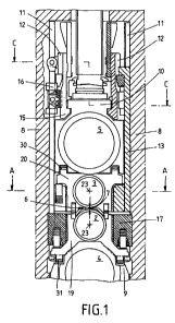
FIG. 1 is a section through a roll stand with one work-
roll pair and one backing-roll pair,
FIG. 2 is a section through the upper work roll from FIG.
1 taken on section plane A B A,
FIG. 3 is a section through a roll stand taken on section
plane B B B of FIG. 2, and
FIG. 4 is another section taken on a line C B C of FIG.
1.
A roll stand indicated overall at 1 (FIG. 1, 2) is
designed as a so-called four-roll frame and comprises two work
rolls 2, 3 and two backing rolls 4, 5. A different number of rolls
is also possible, for example, a design of a six roll frame with
additional intermediate rolls between the work rolls 2, 3 and the
backing rolls 4, 5. Between the work rolls 2, 3 and the backing
rolls 4, 5, there is a roll gap 6 for the rolling stock to be
rolled. A height 7 of the roll gap 6, the so-called gap height can
be set.
The rolls 2, 3, 4, 5 are carried in a roll frame 8 (FIG.
1, 2, 4). The roll frame 8 has backing-roll inserts 9, 10 that
carry the lower and the upper backing rolls 4, 5.
Guide bars 11 that are also carried in the roll frame 8
are guided by horizontal traverses 12. Bending arms 13 move the
upper work-roll assembly when the height of the roll gap 6 is set.
- 5 -
CA 02738713 2011-03-28
At their lower ends, the bending arms 13 have thickened regions 14
(FIG. 3). The horizontal traverses 12 are guided on balancing arms
15; bending cylinders 16 act upon them to bend the upper work roll
3. Similarly, the lower work roll 2 is bent by a bending cylinder
17. An alternative bending means for bending the upper work roll 3
is labeled 18.
The bending cylinders 16, 17, as well as alternate 18 act
upon the outer ends of the work rolls 2, 3, and thus exert a force
that is directed vertically outward from the roll gap 6 on the ends
of the rolls 2, 3, corresponding to the force of the rolling stock
that is in effect in the middle section, in order to counteract a
spreading of the work rolls 2, 3 by the rolling stock.
In addition to the so-called positive bending of the work
rolls via bending means 16, 17, as well as alternate 18, for
increasing the setting range for influencing the profile, a so-
called negative work-roll bending can also be effected by
additional piston-cylinder systems 30, 31 (see FIG. 1).
The backing-roll inserts 9, 10 vertically flank work-roll
inserts 19, 20 in which the work rolls 2, 3 are journaled.
Axial shifters 21 are provided at the outer ends of the
work rolls 2, 3.
A piston 22 of each axial shifter 21 is carried by an
abutment 25 on holder arms 24 that can slide horizontally in work-
roll inserts 19, 20. The holder arms 24 are held by lateral
brackets 29 that are fixed on the outside of the roll frame 8 and
prevent horizontal movement of the holder arms 24 parallel to a
roll axis 23. As a result, the piston 22 is also fixed axially in
- 6 -
CA 02738713 2011-03-28
the axial shifter 21. The holder arms 24 are displaceable
vertically in the lateral brackets 29.
The invention thus relates to a system that allows
bending as well as displacement of the work rolls 2, 3. The
bending or balancing cylinders 17 that are mounted vertical in
stationary blocks are dedicated to the lower work roll 2. The
bender of the upper work roll 3 is identified by two novel
components: the horizontal traverse 12 and the bending arm 13.
When setting the height of the roll gap 6, the movement
of the upper work-roll assembly is done by the bending arms 13.
The bending arms 13 in turn are guided in bars that are bolted to
the roll stand 8, or alternatively sent directly in recesses in the
roll stand 8. This way the bending arms 13 can be guided in the
middle section of the roll stand beams or alternatively, engage
around the roll stand beams.
The bending or balancing cylinders 16 of the upper work
roll are mounted vertically on the arms 15 of the upper backing
roll 5 and move during positioning of the upper rolls 3, 5 with the
balancing arms 15 and thereby need a comparable small travel, which
is determined by the roll stock wear of the upper rolls 3, 5.
The bending or balancing cylinders act on the horizontal
traverses 12 that are guided in the balancing arms 15 relative to
the upper backing rolls 5, as well as on the guide bars 11. The
bending arms 13, which are suspended on the horizontal traverses
12, exert a vertical force on the inserts relative to the upper
work roll 3.
7 -
CA 02738713 2011-03-28
In an alternative embodiment for bending the upper work
roll, the bending arms 13 are hung directly on the balancing arms
15. The bending or balancing cylinders are thus positioned
relative to the upper work roll 3 in the lower thickened regions of
the bending arms 13.
The bending arms 13 that ensure good guidance of the
upper work roll inserts even for a tall roll gap, simultaneously
absorb those frictional forces that would otherwise skew the
backing-roll inserts 9, 10 during axial displacement of the rolls.
The axial shifters of the work rolls 2, 3 are the
hydraulically actuated piston-cylinder systems 21 located at the
work-roll inserts 19, 20 on the side of the operator. Here the
piston of the cylinder unit is connected with the holder arms
guided in the respective insert. Interlocks that are located at
the outer side of the two beams of the roll frame stand on the side
of the operator prevent horizontal displacement of the holder arms
during rolling operation and thus an axial displacement of the
cylinder piston. As a result of the application of pressure on the
piston side or on the pin side of the piston-cylinder unit, an
axial displacement of the work rolls 2, 3 mounted in the inserts
19, 20 is realized.
8 -