Note: Descriptions are shown in the official language in which they were submitted.
CA 02739095 2011-03-31
UNIVERSAL HOLDING DEVICE
FIELD OF THE INVENTION
The present invention relates, generally, to holding devices. More
specifically, the
invention relates to holding devices for handling, transporting, raising and
lowering of
containers such as compressed gas cylinders, open drums and related objects.
BACKGROUND OF THE INVENTION
In the industrial and mechanical industry where compressed gas cylinders, open
drums
and related objects are used there are few methods to safely handle these
objects, in
particular the raising and lowering of objects to and from different heights
of a work
area. Many methods used today are cumbersome and are time consuming.
For example, it is common practice to lower compressed gas cylinders from one
level of
a job site to another level by means of large bulky cage type carriers,
complicated sling
arrangements or strapping the cylinders to other secure items such as a cart
or pallet.
Unavoidably, physical manual labour is required throughout the process. Tools
available
for this type of application are inefficient because of their size, cost and
time involved to
use them properly. They have a limited practical use and as a result these
cylinders are
often handled manually and/or unsafely (such as tying a rope around them)
resulting in
possible damage to equipment, property and personal injury.
It is also a common practice to move compressed cylinders along the same level
or plane
by means of tilting and roiling the cylinder. This is very difficult when
encountering
uneven terrain.
1
CA 02739095 2011-03-31
There is a need in today's society for universal type holding devices with
simple design
that facilitate a fast and convenient way to safely secure objects during
lifting and
placement within the work area without any additional tools. One type of
device may
comprise a collar and pivotally mounted gripping members that could easily be
slipped
onto or engaged with an object. The weight of an object enables a frictional
gripping
force via the pivotally mounted gripping members and as a result, the
frictional gripping
force that is applied to the object increases as the weight of an object
increases. The
collar and grips may be slid over an object, which will enable the object to
be.picked up
by personnel or machine with very little effort or time consumed. Handles may
be
incorporated into the device that facilitates personnel to safely lift and
carry an object or
a cable, chain or rope from a machine may be attached to each grip of the
collar. Such a
device could facilitate the safe lifting and carrying of objects such as
cylinders with much
less effort and their simple design enables one person with a fast and
convenient way to
safely secure the cylinder for lifting and placement within the work area
without any
additional tools.
The prior art has attempted to address this need for simple holding devices
comprising of
pivotally mounted gripping members that could facilitate a fast and convenient
way to
safely secure objects.
For example, United Kingdom Patent Application Publication No. 2333554A
discloses a
carrier device that comprises a frame, which can be placed around an object
such as a
cylinder. These handles may be linked to a rope or wire allowing the object to
be lifted
by a machine. The collars and grips are shaped in a variety of ways.
United States Patent No. 4,795,202 also discloses a lifting handle type device
for
pressurised gas containers which has a circular metal band that have cut outs
for a
receiving pivot mount that support the wedging members. The circular metal
band is
placed around a container when used.
2
CA 02739095 2011-03-31
United States Patent No. 4,463,978 discloses a device for engaging cylindrical
diving
tanks which has a clamping ring for engaging the peripheral surface of the
diving tank in
an unclamped state and for frictionally engaging the peripheral surface of the
diving tank
in a clamped state. This device also comprises a cam that is pivotally
attached to the ring
and a handle that is mounted onto the cam.
The prior art as of yet does not envisage or indeed teach a design and
structure of simple
holding devices comprising pivotally mounted gripping members that are more
universal
in nature and are able to apply frictional gripping forces to the outside or
inside of objects
such as compressed gas cylinders and open drums. The use of better shaped and
designed pivotally mounted gripping members is a possible strategy to embody
such
features into a holding device.
The present invention was conceived and developed having regard to the known
prior art
and with the purpose of providing improved holding devices that are more
universal, and
that comprise pivotally mounted gripping members.
3
CA 02739095 2011-03-31
SUMMARY OF THE INVENTION
An object of the present invention is to provide a holding device.
According to an aspect of the present invention, there is provided a holding
device for
placement about the inside or outside of an object comprising at least one
collar member
that has two mounting portions that extend from each end of the at least one
collar
member, a gripping member that is pivotally mounted between the two mounting
portions from the at least one collar member, a means for pivotally mounting
the gripping
member between the two mounting portions from the at least one collar member
wherein
the gripping member is mounted at a pivot point that enables a gripping
portion of the
gripping member to grip the object and a user member that extends from the end
of the
gripping member away from the gripping portion for providing an external force
to that
is transferred to the gripping member.
The holding device is in an enclosed configuration and the object is enclosed
by the
holding device when in use.
According to an aspect of the present invention, there is provided a holding
device
wherein the gripping member is of a smooth asymmetrically boot shaped design
that
enables the holding device to grip the object from the outside of the object
with in an
inward gripping motion or from the inside of the object with outward gripping
motion
and provides a large gripping surface for contact point with the object.
30
4
CA 02739095 2011-03-31
BRIEF DESCRIPTION OF THE DRAWINGS
The present invention will be further described with reference to the
accompanying
drawings, in which:
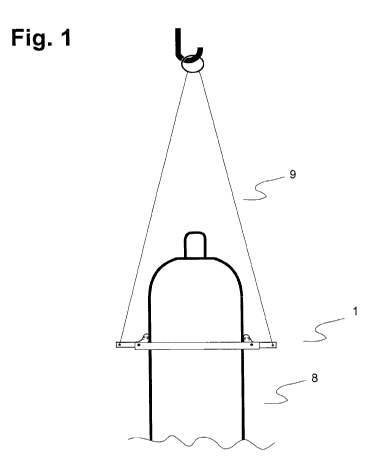
Fig. 1 illustrates a side view of a holding device according to an aspect of
the present
invention wherein it is holding a gas cylinder,
Fig. 2 illustrates a side view of a holding device according to an aspect of
the present
invention wherein it is holding an open drum,
Fig. 3 illustrates an exploded view of a holding device according to an aspect
of the
present invention; and
Fig. 4 illustrates a top view of a holding device according to an aspect of
the present
invention.
5
CA 02739095 2011-03-31
DETAILED DESCRIPTION OF THE INVENTION
A better understanding of the present invention and its objects and advantages
will
become apparent to those skilled in this art form the following detailed
description,
wherein there is described only the preferred embodiment of the invention,
simply by
way of illustration of the best mode contemplated for carrying out the
invention. As will
be realized, the invention is capable of modifications in various obvious
respects, all
without departing from the scope and spirit of the invention. Accordingly, the
description should be regarded as illustrative in nature and not as
restrictive.
Several embodiments of universal holding devices comprising of pivotally
mounted
gripping members are described below that are designed to apply frictional
gripping
forces to the outside or inside of an object such as compressed gas cylinders
and open
drums. The use of better shaped and designed pivotally mounted gripping
members
facilitates such holding devices for gripping objects with in an inward
gripping motion or
outward gripping motion. For example, a universal holding device according to
the
present invention may be used to hold a compressed gas cylinder wherein the
gripping
force is applied to the outside of the cylinder in an inward motion (see Fig.
1). The same
holding device according to the present invention wherein the device is
oriented in a
manner in which the pivotally mounted gripping members point downwards may be
used to hold a open drum wherein the gripping force is applied to the inside
of the drum
in an outward motion (see Fig. 2). Accordingly, there is provided holding
devices 1 for
placement about the inside or outside of an object(s) comprising of at least
one collar
member 2 wherein said at least one collar member has two mounting portions 3
that
extend from each end of said at least one collar member, at least one gripping
member 4
that is pivotally mounted between two mounting portions from at least one
collar
member, a means for pivotally mounting said at least one gripping member 5
between
two mounting portions from at least one collar member and at least one user
member 6
that extends from the end of said at least one gripping member. The holding
devices
6
CA 02739095 2011-03-31
according to the present invention are in a closed configuration. An example
of a
holding device according to the present invent is illustrated in Fig. 3.
According to an aspect of the present invention the pivotally mounted gripping
members
4 that are provided are shaped and designed in a manner that facilitates
holding devices
capable of gripping objects with in an inward gripping motion or outward
gripping
motion (see Fig. 3). Preferably, the pivotally mounted gripping members 4 are
asymmetrically. boot shaped and are substantially rounded to alleviate the
risk of
damaging the carried object. This boot shaped design may facilitate the
present invention
for being more universal towards the type and size of the object that can be
carried, in
addition to providing a large gripping surface/portion area resulting in a
more favourable
contact point with an object. The shape of the gripping members allows for a
more
flexible fit of the lifting unit without the need for making adjustments every
time the unit
is moved from one object to another without effecting the gripping action, and
also
allows for the lifting unit to be used on various size objects within the
collar size range.
The shape and size of the gripping members may also allow the gripping members
to
open and close with very little effort on the operator's part, with no binding
or jamming
of the gripping members. This is facilitated by the edgeless design of the
gripping
members. The shape and design of the gripping members may allow attachments to
be
20, installed on the gripping members for various functions (such as a remote
"open"
attachment). Also with the shape of the gripping members the same unit may be
used for
both gripping the outside of a container or with the reversing of the gripping
members,
the inside of a container. The pivotally mounted gripping members may comprise
a pivot
hole 7 to be used in conjunction with a pivoting mounting means 5. It is
preferable that
the pivotally mounted gripping members are serrated at the gripping surface
portion for
increasing friction during gripping use. It is also preferable that there are
multiple
gripping portions on the gripping members as shown in Fig. 3. Furthermore, a
rubber
type coating may be employed on the gripping surface portion to provide a more
favourable contact point with an object, depending on type of application. The
pivotally
mounted gripping members may be made from a variety materials, however, it is
preferable that they comprise of metal or plastic materials.
7
CA 02739095 2011-03-31
Referring to Fig. 4, there is illustrated in an above view, a holding device 1
in accordance
with an embodiment of the present invention comprising pivotally mounted
gripping
members 4 in the closed position, user members 6 and collar members 2 wherein
the
device is fitted over a compressed gas cylinder 8. The device may have two
collar
members 2 which are shaped and sized for the cylinder 8, with bolt holes
drilled at each
end as shown, joined together with suitable bolts 5a, washers 5b and lock-nuts
5c which
make up a means for pivotally mounting said gripping members 5. The collar
members
may be formed from steel flat bar and the gripping members may be formed from
a steel
plate with a pivot hole 7. However, this should not be considered limiting and
the collar
members and gripping members may be formed from other suitable materials.
Preferably,
the holding device has user members 6 that extend from the gripping members.
The user
members 6 optionally may have a lifting eye 10 as shown in Fig. 3 that may be
used to
attach a wire or cable.
Means for pivotally mounting are commonly known in the art, and are not
specific to the
invention. Thus, it will be known to one skilled in the art how to integrate
such a means
with the holding devices described herein. Some examples may include bolt, nut
and
washer assemblies and axle and bearing assemblies, however, these examples
should not
be considered limiting.
Referring to Fig. 3, there is illustrated in an exploded view, a holding
device 1 in
accordance with an embodiment of the present invention wherein bolts 5a,
washers 5b
and lock-nuts 5c (i.e. a means for pivotally mounting 5 the gripping members
4) join the
collars members 2 together, with the gripping members 4 pivotally mounted
between the
collar members 2 at the mounting portion 3. These bolts facilitate 5a three
functions: 1) a
means to join the sections of the collar members together; 2) a means to
adjust the collar
to the desired fit on the cylinder; and 3) to provide the pivot pin for the
gripping
members, which may move freely on the bolt and between two mounting portions.
The
gripping members 4 may have serrated type edges on the contact faces to assist
with the
gripping action on the cylinder as shown.
8
CA 02739095 2011-03-31
Referring to Fig. 1, there is illustrated in a side view, a holding device 1
in accordance
with an embodiment of the present invention wherein a lifting cable 9 is
attached to the
lifting eyes of the gripping members and an upward force is applied. As a
result the first
gripping portion of the each of the gripping members are forced against the
cylinder 8,
thereby gripping the cylinder with sufficient force to hold and lift the
cylinder. When the
upward force is removed and the lifting cable becomes slack, the first
gripping portion of
each of the gripping members are released from gripping the cylinder, allowing
for the
holding device to be easily removed from one cylinder and set on another
cylinder ready
for immediate use.
The embodiments of the present invention shown in Fig. 1-4 comprise of two
gripping
members, two collar members and two means for pivotally mounting said gripping
members, however, the number of these elements may vary with a similar
construction as
that is described and illustrated. Preferably, the gripping members are evenly
spaced.
According to another embodiment of the present invention user member may be in
the
form of a handle extending from the gripping member allowing personnel the
ability to
physically pick up and move an object such as cylinder without the aid of
machinery.
According to yet another embodiment of the present invention a holding device
may
comprise a means for remotely disengaging the gripping members from an object
(for
example a trip wire type assembly) attached to the gripping members to allow
an
operator the ability to place the gripping member in the non-gripping position
from a
remote location away from the vicinity of the device. This type of arrangement
would be
useful for such applications as an attachment to a forklift type machine
moving cylinders
about, either at a job site, within a warehouse or for the loading of
cylinders to trucks etc.
According to a further embodiment of the present invention a holding device
may be
used to move and carry smaller personal objects such as smaller compressed gas
cylinders. Preferably, the holding device comprises one gripping member with a
handle
9
CA 02739095 2011-03-31
extending from it. Optionally, a stand type attachment can be incorporated
where a
second gripping member would be.
The simple design of the described holding devices according to the present
invention
afford their simple use and operation. For example as shown in Fig 1., the
holding
devices according to the present invention may be slipped over a cylinder 8
with the
pivotally mounted gripping members 4 naturally facing outward. A cable, chain
or rope 9
from a crane or pulley system, etc. may be attached to each user member. As
tension is_.
applied to the cable, chain or rope 9, the pivotally mounted gripping members
are forced
inward against the cylinder to grip and hold the cylinder. The gripping
members 4 hold
the cylinder and are locked in place until the cable tension is released (i.e.
cylinder at
rest). With no cable tension the gripping members naturally release outward
and the
collar may be slid off the cylinder. Furthermore, due to the present
invention's
convenient size it may be left on the cylinder for future use without
competing with other
equipment at the work site for storage space.
Alternatively, the same holding device 1 according to the present invention
wherein the
device is oriented in a manner in which the pivotally mounted gripping members
point
downwards may be used hold an object from the inside such as an open drum 11
(see
Fig. 2). Referring to Fig. 2, there is illustrated in a side view, a holding
device 1 in
accordance with an embodiment of the present invention wherein a lifting cable
9 is
attached to the lifting eyes of the gripping members and an upward force is
applied. Its
use and operation may occur in a similar manner as described above. As a
result the first
gripping portion of the each of the gripping members are forced against the
open drum
11, thereby gripping the open drum 11 with sufficient force to hold and lift
the open
drum 11. When the upward force is removed and the lifting cable becomes slack,
the
first gripping portion of each of the gripping members are released from
gripping the
open drum 11, allowing for the holding device to be easily removed from one
cylinder
and set on another open drum llready for immediate use.
While one (or more) embodiment(s) of this invention has (have) been
illustrated in the
CA 02739095 2011-03-31
accompanying drawings and described above, it will be evident to those skilled
in the art
that changes and modifications may be made therein without departing from the
essence
of this invention. All such modifications or variations are believed to be
within the sphere
and scope of the invention as defined by the claims appended hereto.
Furthermore, the features and elements of the embodiments described and
illustrated may
be combined providing other embodiments of the present invention.
INDUSTRIAL APPLICABILITY
The invention provides universal holding devices comprising of pivotally
mounted
gripping members that are designed to apply frictional gripping forces to the
outside or
inside of an object such as compressed gas cylinders and open drums. The use
of better
shaped and designed pivotally mounted gripping members facilitates such
holding
devices for gripping objects with in. an inward gripping motion or outward
gripping
motion. Such devices could facilitate the safe lifting and carrying of objects
such as
cylinders with much less effort and their simple design enables one person
with a fast and
convenient way to safely secure a cylinder for lifting and placement within
the work area
without any additional tools.
11