Note: Descriptions are shown in the official language in which they were submitted.
CA 02739097 2016-02-24
=
88100-1
METHOD AND APPARATUS FOR TISSUE GRAFTING
FIELD OF THE INVENTION
The present disclosure relates to exemplary embodiments of method and
apparatus for
providing tissue grafts using tissue from a donor site.
BACKGROUND INFORMATION
An autograft can refer to tissue transplanted from one part of an individual's
body (e.g.,
a "donor site") to another part (e.g., a "recipient site"). Autografts can be
used, for example, to
replace missing skin and other tissue and/or to accelerate healing resulting
from trauma, wounds,
.. burns, surgery and birth defects. Availability of tissue for autografting
can be limited by
characteristics of candidate donor sites, including a number and/or total area
of tissue grafts,
healing behavior of the donor site, similarity of the donor and recipient
sites, aesthetic
considerations, etc.
Skin grafting can be performed surgically. For example, a conventional
autograft
procedure may include excision or surgical removal of burn injured tissue,
choosing a donor site,
which may be an area from which healthy skin is removed to be used as cover
for the cleaned
burned area, and harvesting, where the graft may be removed from the donor
site, e.g., using an
instrument similar to an electric shaver. Such instrument (e.g., a dermatome)
can be structured to
gently shave a piece of tissue, which may be, e.g., about 10/1000 of an inch
thick for a split-
thickness graft, from the skin at the unburned donor site to use as a skin
graft. The skin graft can
then be placed over the cleaned wound so that it can heal. Donor skin tissue
can be removed to
such a depth that the donor site can heal on its own, in a process similar to
that of healing of a
second degree burn.
Two conventional types of autografts which may be used for a permanent wound
.. coverage include sheet grafts and meshed grafts. A sheet graft can refer to
a piece of skin tissue
removed from an undamaged donor site of the body, in a process that may be
referred to as
harvesting. The size of the donor skin piece that is used may be about the
CA 02739097 2011-03-30
WO 2009/146068
PCMJS2009/039114
same size as the damaged area. The sheet graft can be laid over the excised
wound, and
stapled or otherwise fastened in place. The donor skin tissue used in sheet
grafts may not
stretch significantly, and a sheet graft can be obtained that is slightly
larger than the
damaged area to be covered because there may often be a slight shrinkage of
the graft
tissue after harvesting.
Sheet grafts can provide an improved appearance of the repaired tissue site.
For example, sheet grafts may be preferred for use on large areas of the face,
neck and
hands if they are damaged, so that these more visible parts of the body can
appear less
scarred after healing. A sheet graft may be used to cover an entire burned or
damaged
region of skin, e.g., if the damaged site is small. Small areas of a sheet
graft can be lost
after placement because of a buildup of fluid (e.g., a hematoma) can occur
under the sheet
graft following placement the sheet graft.
Sheet grafts may be full-thickness or split-thickness. For example, split-
thickness skin grafts can be used to cover wounds in burn and skin ulcer
patients. A
conventional split-thickness graft can be formed, e.g., by harvesting a sheet
of epidermis
and upper dermal tissue from a donor site, in a procedure similar to that of
peeling an
apple. The split-thickness graft can then be placed on the location of the
burn or ulcer.
The skin tissue may then grow back at the donor site following a generally
extended
healing time. Split-thickness grafts may be preferable to full-thickness
grafts because
removing large amounts of full-thickness skin tissue from the donor site can
lead to
scarring and extensive healing times at the donor site, as well as an
increased risk of
infection. However, skin tissue removed from the donor site for a split-
thickness skin
autograft can include only a thin epithelial layer, which can lack certain
elements of the
dermis that improve structural stability and normal appearance in the
recipient site.
Full-thickness skin grafts can be formed using sheets of tissue that include
the
entire epidermis layer and a dermal component of variable thickness. Because
the dermal
component can be preserved in full-thickness grafts, more of the
characteristics of normal
skin can be maintained following the grafting procedure. Full-thickness grafts
can contain
a greater collagen content, dermal vascular plexus, and epithelial appendages
as compared
to split-thickness grafts. However, full-thickness grafts can require more
precise
conditions for survival because of the greater amount of tissue requiring
revascularization.
Full-thickness skin grafts can be preferable for repairing, e.g., visible
areas of
the face that may be inaccessible by local flaps, or for graft procedures
where local flaps
CA 02739097 2011-03-30
WO 2009/146068
PCMJS2009/039114
are contraindicated. Such full-thickness skin grafts can retain more of the
characteristics of
normal skin including, e.g., color, texture, and thickness, as compared to
split-thickness
grafts. Full-thickness grafts may also undergo less contraction while healing.
These
properties can be important on more visible areas such as the face and hands.
Additionally, full-thickness grafts in children can be more likely to grow
with the
individual. However, application of conventional full-thickness skin grafts
can be limited
to relatively small, uncontaminated, well-vascularized wounds, and thus may
not be
appropriate for as many types of graft procedures as split-thickness grafts.
Additionally,
donor sites for full-thickness grafts can require surgical closure or
resurfacing with a split-
thickness graft.
A meshed skin graft can be used to cover larger areas of open wounds that may
be difficult to cover using sheet grafts because of, e.g., a lack of a
sufficient area of healthy
donor sites. Meshing of a skin graft can facilitate skin tissue from a donor
site to be
expanded to cover a larger area. It also can facilitate draining of blood and
body fluids
from under the skin grafts when they are placed on a wound, which may help
prevent graft
loss. The expansion ratio (e.g., a ratio of the unstretched graft area to the
stretched graft
area) of a meshed graft may typically be between about 1:1 to 1:4. For
example, donor
skin can be meshed at a ratio of about 1:1 or 1:2 ratio, whereas larger
expansion ratios may
lead to a more fragile graft, scarring of the meshed graft as it heals, and/or
extended
healing times.
A conventional graft meshing procedure can include running the donor skin
tissue through a machine that cuts slits through the tissue, which can
facilitate the
expansion in a pattern similar to that of fish netting or a chain-link fence.
Healing can
occur as the spaces between the mesh of the stretched graft, which may be
referred to as
gaps or interstices, fill in with new epithelial skin growth. However, meshed
grafts may be
less durable graft than sheet grafts, and a large mesh can lead to permanent
scarring after
the graft heals.
To help the graft heal and become secure, the area of the graft can preferably
not be moved for at least about five days following each surgery. During this
immobilization period, blood vessels can grow from underlying tissue into the
skin graft,
and can help to bond the two tissue layers together. About five days after the
graft is
placed, exercise therapy programs, tub baths, and other normal daily
activities can often be
resumed. Deep second-degree and full-thickness bums may require skin graft
surgery for
CA 02739097 2011-03-30
WO 2009/146068
PCMJS2009/039114
quick healing and minimal scarring. Large burn sizes can lead to more than one
grafting
procedure during a hospital stay, and may require long periods of
immobilization for
healing.
As an alternative to autografting, skin tissue obtained from recently-deceased
people (which may be referred to, e.g. as a homograft, an allograft, or
cadaver skin) can be
used as a temporary cover for a wound area that has been cleaned. Unmeshed
cadaver skin
can be put over the excised wound and stapled in place. Post-operatively, the
cadaver skin
may be covered with a dressing. Wound coverage using cadaveric allograft can
then be
removed prior to permanent autografting.
A xenograft or heterograft can refer to skin taken from one of a variety of
animals, for example, a pig. Heterograft skin tissue can also be used for
temporary
coverage of an excised wound prior to placement of a more permanent autograft,
and may
be used because of a limited availability and/or high expense of human skin
tissue. In
some cases religious, financial, or cultural objections to the use of human
cadaver skin may
also be factors leading to use of a heterograft. Wound coverage using a
xenograft or an
allograft is generally a temporary procedure which may be used until
harvesting and
placement of an autograft is feasible.
Epithelial appendages can preferably be regenerated following a grafting
procedure. For example, hair can be more likely to grow from full-thickness
grafts than
from split-thickness grafts, but such hair growth may be undesirable based on
the location
of the wound. Accordingly, donor sites for full-thickness grafts can be
carefully selected
based in part, e.g., on patterns of hair growth at the time of surgery.
Further, certain hair
follicles may not be oriented perpendicular to the skin surface, and they can
be transected
if an incision provided to remove graft tissue is not oriented properly.
Sweat glands and sebaceous glands located in graft tissue may initially
degenerate following grafting. These structures can be more likely to
regenerate in full-
thickness grafts than in split-thickness grafts because full-thickness grafts
can be
transferred as entire functional units. For example, sweat gland regeneration
can depend in
part on reinnervation of the skin graft with recipient bed sympathetic nerve
fibers. Once
such ingrowth has occurred, the skin graft can assume the sweating
characteristics of the
recipient site, rather than retaining the characteristics of the donor site.
In contrast,
sebaceous gland regeneration may be independent of graft reinnervation and can
retain the
characteristics of the donor site. Prior to the regeneration, the skin graft
tissue may lack
CA 02739097 2011-03-30
WO 2009/146068
PCMJS2009/039114
normal lubrication of sebum produced by these glands, which can make such
grafts more
susceptible to injury.
In general, grafting procedures may be limited by the amount of tissue which
can be removed from the donor site without causing excessive adverse effects.
Full-
thickness grafts can provide improved tissue quality at the wound site, but
the donor site
may be more severely disfigured as described above. Split-thickness grafts can
be a
compromise between healing times and aesthetic and functional properties of
the donor
and recipient sites, whereas meshing can provide more extensive graft coverage
at the
expense of visible scarring.
Harvesting of graft tissue from the donor site generally can generate
undesirable large-scale tissue damage to the donor site. On the other hand,
small areas of
skin wounding adjacent to healthy tissue can be well-tolerated and may heal
quickly. Such
healing of small wounds can occur in techniques such as "fractional
photothermolysis" or
"fractional resurfacing," in which patterns of damage having a small dimension
can be
created in skin tissue. These exemplary techniques are described, e.g., in
U.S. Patent No
6,997,923 and U.S. Patent Publication No. 2006/0155266. Small-scale damage
patterns
can heal quickly by regrowth of healthy tissue, and can further provide
desirable effects
such as skin tightening without visible scarring.
In view of the shortcomings of the above described procedures for tissue
grafting, it may be desirable to provide exemplary embodiments of method and
apparatus
that can provide tissue suitable for grafting while minimizing unwanted damage
to the
donor sites.
SUMMARY OF EXEMPLARY EMBODIMENTS
Exemplary embodiments of the present disclosure provide method and
apparatus for obtaining small portions of graft tissue that can be accompanied
by rapid
healing of the donor site. For example, the exemplary embodiment of the method
can be
provided for obtaining skin graft tissue by harvesting small portions of the
tissue, e.g.,
micrografts, from a donor site.
Such micrografts can comprise skin tissue that can include, e.g., epidermal
and
dermal tissue, and/or tissue obtained from other body organs. The micrografts
can have at
least one dimension that is relatively small, e.g., less than about 1 mm, or
less than about
0.5 mm, or optionally about 0.3 mm or less, or about 0.2 mm. Such exemplary
small
CA 02739097 2011-03-30
WO 2009/146068
PCMJS2009/039114
dimensions of the micrografts can facilitate both healing of the donor site
following
harvesting and viability of the micrografts by allowing greater diffusional
nourishment of
the micrograft tissue. The small regions of damage in the donor site caused by
a removal
of the tissue portions can heal rapidly with little or no formation of visible
scars. The
micrografts obtained from skin tissue can include, e.g., epidermal and dermal
tissue, and
can also include stem cells that can be located proximal to the dermal/fatty
layer boundary.
The micrografts can also be obtained from other types of tissue, e.g., various
internal
organs or the like.
A fraction of dermal tissue that is removed from a donor site can be, e.g.,
less
than about 70%, or less than about 50%, although other fractions may be used.
The
harvested tissue portions can be in the shape of cylinders, elongated strips,
or other
geometries which can include at least one small dimension. In certain
exemplary
embodiments, a portion of the tissue at the donor site can be frozen or
partially frozen.
Such freezing can facilitate cutting, removal and/or viability of the
harvested tissue
portions.
An exemplary embodiment of the apparatus can be provided for harvesting
micrografts that can include a hollow tube. An inner diameter of the hollow
tube can be
approximately the same size as a diameter or width of the micrograft to be
harvested. A
distal end of the hollow tube can have two or more points to facilitate
separation of the
micrografts from the surrounding tissue.
The micrografts can be harvested from the donor site by inserting the
exemplary apparatus into tissue at the donor site to a particular depth
thereof, and then
removing the tube. A stop can be provided on the tube to control or limit the
depth of
insertion of the tube. A slight suction or pressure can be provided at a
proximal end of the
tube to facilitate harvesting of the micrografts and/or their removal from the
tube.
A further exemplary embodiment of the apparatus can be provided that
includes a plurality of such tubes for simultaneous harvesting of a plurality
of micrografts.
An enclosure and/or a source of pressure, e.g., a pump or the like, can be
provided in
communication with the proximal ends of the tubes to facilitate application of
pressure
and/or suction to the plurality of tubes. A vibrating arrangement can be
coupled to the
apparatus to facilitate the insertion of the tubes into the donor site.
The exemplary micrografts can be placed in a biocompatible matrix, e.g., to
form a graft or directly into tissue at the recipient site The biocompatible
matrix can be
88100-1
formed using collagen, polylactic acid, hyaluronic acid, and/or other
substances which can support the
harvested micrograft tissue portions and promote their growth. The matrix can
optionally include, e.g.,
nutrients and/or other substances to promote tissue growth. The harvested
tissue portions can be bonded
to the matrix using techniques such as photochemical tissue bonding to provide
structural stability. The
matrix can then be applied to the recipient site, which can promote growth and
revascularization of the
tissue portions to form a continuous sheet of the grafted tissue.
The exemplary micrografts can also be gathered in a compact configuration to
form graft
tissue that can be applied directly to a recipient site. The exemplary
micrografts can also be inserted
directly into the tissue at a recipient site such as, e.g., scar tissue,
using, e.g., the exemplary hollow tubes
described herein.
In accordance with another aspect, the invention relates to an apparatus for
grafting at least
one biological tissue. The apparatus comprises a plurality of hollow tubes
having a distal end and a
proximal end, wherein each of the hollow tubes comprises at least two points
provided at the distal end
thereof. The inner diameter of each of the hollow tubes is I mm or less. The
distal end of each of the
hollow tubes is structured to be inserted into the at least one biological
tissue at a donor site to remove at
least one portion of a graft tissue therefrom when the distal ends of the
hollow tubes are withdrawn from
the donor site. The plurality of tubes are configured to simultaneously remove
the portions of graft tissue
from the donor site.
In accordance with another aspect, the invention relates to a use of at least
one hollow tube
for grafting at least one biological tissue. The hollow tube comprises a
distal end suitable for insertion
into a first location of a donor site of the biological tissue and for
removing a first portion of the
biological tissue therefrom. The distal end is also suitable for re-insertion
at a further location on the
donor site, such that each time the at least one hollow tube is inserted into
the donor site, the portion of
the biological tissue removed from the donor site pushes the portion of the
biological tissue above it
toward a proximal end of the hollow tube. The portions of the biological
tissue pushed out of the
proximal end of the at least one hollow tube are stored in an enclosure
coupled to the proximal end of
the at least one hollow tube. The transfer of the enclosure to a recipient
site allows for distribution of the
portions of the biological tissue to the recipient site.
These and other objects, features and advantages of the present disclosure
will become apparent
upon reading the following detailed description of exemplary embodiments of
the
CA 2739097 2018-03-05
CA 02739097 2014-07-04
' 4
W7904-10
present disclosure, when taken in conjunction with the appended claims.
BRIEF DESCRIPTION OF TI IE DRAWINGS
Further objects, features and advantages of the present disclosure will become
apparent
from the following detailed description taken in conjunction with the
accompanying figures
showing illustrative embodiments, results and/or features of the exemplary
embodiments of the
present disclosure, in which:
Fig. IA is a schematic illustration of an exemplary donor site after
cylindrical portions
of micrograft tissue have been harvested therefrom;
Fig. IB is a schematic illustration of the exemplary donor site shown in Fig.
IA after
healing has occurred;
Fig. IC is a schematic illustration of an exemplary micrograft that may be
removed from
the exemplary donor site shown in Fig. IA;
Fig. 2A is a cross-sectional view of an exemplary graft prepared by providing
harvested
micrograft tissue portions in a biocompatible matrix;
Fig. 2B is a is a cross-sectional view of the exemplary graft shown in Fig. 2A
30 after it
has been placed over a wound and some regrowth has occurred;
Fig. 3A is a schematic illustration of another exemplary donor site after
elongated
strips of tissue have been harvested therefrom;
--7a - -
CA 02739097 2011-03-30
WO 2009/146068
PCMJS2009/039114
Fig. 313 is a schematic illustration of the exemplary donor site shown in Fig.
3A
after healing has occurred;
Fig. 3C is a schematic illustration of an exemplary tissue strip that may be
removed from the donor site shown in Fig. 3A;
Fig. 4A is a schematic view in plan of a plurality of exemplary cylindrical
micrograft tissue portions provided in a compact arrangement to form a graft;
Fig. 4B is a side view of the exemplary micrograft tissue portions shown in
Fig. 4A;
Fig. SA is a schematic illustration of an exemplary apparatus that can be used
to harvest micrograft tissue in accordance with first exemplary embodiments of
the present
disclosure;
Fig. SR is a schematic illustration of the exemplary apparatus that can be
used
to harvest the micrograft tissue in accordance with second exemplary
embodiments of the
present disclosure;
Fig. 6A is a schematic illustration of the exemplary apparatus shown in Fig.
5A
that is inserted into an exemplary donor site to harvest an exemplary
micrograft;
Fig. 6B is a schematic illustration of the exemplary apparatus shown in Fig.
SA
that contains the harvested micrograft;
Fig. 6C is a schematic illustration of the exemplary apparatus shown in Fig.
SA
showing the harvested micrograft being removed therefrom;
Fig. 7 is a schematic illustration of the exemplary apparatus that can be used
to
harvest micrograft tissue in accordance with third exemplary embodiments of
the present
disclosure;
Fig. 8A is an exemplary image of a distal end of the exemplary apparatus that
includes two points;
Fig. 813 is a further exemplary image of the distal end of the exemplary
apparatus shown in Fig. 7A; and
Fig. 9 is an exemplary image of the micrografts obtained using the exemplary
apparatus shown in Figs. 7-8B.
Throughout the drawings, the same reference numerals and characters, unless
otherwise stated, are used to denote like features, elements, components, or
portions of the
illustrated embodiments. Moreover, while the present disclosure will now be
described in
-- 8 --
CA 02739097 2011-03-30
WO 2009/146068
PCMJS2009/039114
detail with reference to the figures, it is done so in connection with the
illustrative
embodiments and is not limited by the particular embodiments illustrated in
the figures.
DETAILED DESCRIPTION OF EXEMPLARY EMBODIMENTS
Exemplary embodiments of the present disclosure provide methods and
apparati for producing autografts, and particularly such methods and apparati
which can
facilitate more rapid healing of the donor site while providing improved
tissue
characteristics at the recipient site. Exemplary embodiments of the present
disclosure can
include a plurality of small-scale tissue portions (e.g., micrografts) that
can be used to
provide autografts. Such micrografts can avoid significant permanent damage to
the donor
site while providing graft tissue that can heal rapidly and generate skin
tissue having
desirable properties at the recipient site.
In exemplary embodiments of the present disclosure, a method can be provided
for creating autografts in which tissue portions having at least one small
dimension (e.g.,
micrografts) are harvested from an exemplary donor site 100, as shown in Fig.
1A. The
holes 110 shown in Fig. lA represent regions of the exemplary donor site 100
from which
tissue portions (e.g., micrografts) have been removed. These exemplary holes
110 may
have an approximately round cross-sectional shape, although other shapes may
be used.
The exemplary donor site 100 is shown in Fig. 1B after healing of the
harvested tissue has occurred. The small regions of damage 100 created at the
donor site
by the removed tissue can heal rapidly and/or without visible scarring. For
example, the
residual pattern of the healed donor site 100 shown in Fig. 18 may not be
easily
perceptible by the naked eye under normal viewing conditions.
An exemplary micrograft 120 that can be formed, e.g., by harvesting or
removing a portion of the tissue from the donor site 100 to form the hole 110
therein, is
shown in Fig. 1C. The exemplary micrograft 120 can have an elongated shape
that may be
approximately cylindrical. The micrografts 120 can include both epidermal
tissue 130 and
dermal tissue 140 from the exemplary donor site 100. For example, the
exemplary
micrograft 120 can be about 3 mm in length, which can correspond to a typical
total depth
of the skin layer (e.g., epidermal and dermal layers). A different length may
be used based
on the particular skin or tissue characteristics of the donor site 100. In
general, it can be
preferable to avoid harvesting a significant amount of subcutaneous tissue, so
the harvested
micrografts 200 can include primarily the epidermal tissue 130 and the dermal
tissue 140.
--9--
CA 02739097 2011-03-30
WO 2009/146068
PCMJS2009/039114
A lower portion 150 of the exemplary micrograft 120 can also include stem
cells that can
be present in a lower portion of the dermal layer of the donor site 100 (e.g.,
near a
dermal/fatty layer boundary).
A width or diameter of the holes 110 produced during harvesting (which can
correspond approximately to the diameters of the portions of the harvested
micrografts
120) can be less than about 1 mm, or less than about 0.5 mm. In certain
exemplary
embodiments, the diameter or width can be less than about 0.3 mm, or about 0.2
mm. The
size of the exemplary holes 110 can be selected, e.g., based on the effects of
creating small
damage regions in the donor site 100 which can heal rapidly and/or without
scarring, and
on creating portions of tissue that may be large enough to form a sufficient
amount of graft
tissue.
For example, living tissue can be provided with nutrients via a diffusional
transport over distances of about 0.1 mm. Accordingly, the exemplary
micrografts 120
having at least one dimension that is less than about 0.3 mm or, e.g., about
0.2 mm, can
exhibit improved viability and likelihood to survive, and grow when used in a
graft. Such
exemplary micrografts 120 can be better able to receive nutrients (including,
e.g., oxygen)
when placed in a recipient site, prior to revascularization of the tissue.
Larger micrografts
120 can also benefit from such diffusional transport of nutrients, and can
also be more
likely to survive than significantly larger portions of graft tissue (e.g.,
conventional full-
thickness, split-thickness or meshed grafts).
A fraction of surface tissue removed from the donor site 100 by harvesting
(which can correspond to a fractional surface area of the exemplary donor site
100
occupied by the holes 110) may be less than about 70%, or more preferably less
than about
50%. The fraction of tissue removed can be sufficiently large to provide
enough harvested
micrografts 120 to form a graft therefrom of appropriate size, but small
enough to facilitate
rapid healing at the donor site 100 based on growth from the remaining
undamaged tissue.
Other fractions of tissue can be removed from a donor site 100 depending on
factors such
as, e.g., the particular characteristics of the donor site 100, the size of
the graft needed, and
the overall amount of donor site tissue available.
In further exemplary embodiments of the present disclosure, a graft 200 can be
provided by embedding or inserting a plurality of micrografts 120 in a
biocompatible
matrix 210 as shown, e.g., in Fig. 2A. The exemplary matrix 210 containing the
micrografts 120 can be exposed to nutrients to promote growth of the harvested
--10--
CA 02739097 2011-03-30
WO 2009/146068
PCMJS2009/039114
micrografts 120, e.g., to form a continuous or nearly continuous layer of
tissue in the graft
200 after growth has occurred. The exemplary graft 200, which can include the
matrix 210
and the micrografts 120, may be placed directly over a recipient site 220
(e.g., a cleaned
wound area) as shown in Fig. 2B. The exemplary micrografts 120 can also
include stem
cells as described herein, which can also facilitate healing and integration
of the exemplary
micrografts 120 when they are transplanted to the recipient site 220. The
recipient site 220
can provide nutrients and/or promote revascularization of the harvested
micrografts 120,
which can further enhance their growth through the matrix 210 to eventually
fill in the
spaces separating them. For example, Fig. 2B shows the micrografts 120 after
they have
begun to grow into the surrounding matrix 210.
In one exemplary embodiment, the micrografts 120 can be placed in the matrix
210 at approximately the same spacing (e.g., a similar areal density) as they
were removed
from the donor site 100. This exemplary configuration can generate an amount
of graft
tissue that may be approximately the same size as the overall harvested area
of the donor
site 100 after the micrografts 120 grow and fill in the spaces between them
with new
tissue. The average spacing of the micrografts 120 in the matrix 210 can also
be increased
to form a graft tissue that is larger than the overall area of the harvested
donor site 100.
The particular spacing of the micrografts 120 in a particular graft 200 can be
selected
based on factors such as, e.g., the size and fractional damage of the donor
site 100, the size
of the recipient site 220 to be covered by the skin graft 200, the time needed
for the
micrografts 120 to regrow and form a continuous tissue layer, the desired
appearance of
the grafted recipient site, etc. For example, the exemplary micrografts 120
can be spaced
far apart in a particular graft, which can provide a larger graft area but can
also require
longer healing time and the possibility of some visible scarring or texture in
the healed
graft 200.
In a further exemplary embodiment, tissue portions 320 such as that shown in
Fig. 3C can be harvested in an elongated, narrow strip-like shape. One or more
of the
exemplary tissue strips 320 can include both epidermal tissue 130 as well as
dermal tissue
140, which can be similar to the micrograft 120 shown in Fig. 10. For example,
the height
of the exemplary tissue strip 320 may be about 3 mm, or another length that
may
correspond to a local depth of the dermal layer at the donor site 100. Larger
and/or smaller
depths can also be selected when harvesting tissue strips 320 based on, e.g.,
characteristics
of the donor and recipient sites, the wound to be repaired by grafting, etc.
--11--
CA 02739097 2011-03-30
WO 2009/146068
PCMJS2009/039114
Harvesting of such exemplary tissue strips 320 can leave long, narrow grooves
310 in a donor region 100 as shown, e.g., in Fig. 3A. A width of the grooves
310 (and thus
a width of the harvested tissue strips 320) can be less than about 1 mm, or
less than about
0.5 mm. In certain exemplary embodiments, the width of such tissue strips can
be less
than about 0.3 mm, or about 0.2 mm. As described herein, such a small
dimension can
facilitate diffusional transport of nutrients to the graft tissue and can
improve viability of
the harvested tissue. A depth of the grooves 310 from the skin surface can
correspond to
the height of the harvested strips 320.
A surface area fraction of the exemplary donor site 310 that is removed to
form
tissue strips 320 can be less than about 70%, or about 50% or less. Factors
governing a
selection of parameters associated with the harvested elongated tissue strips
320 (e.g.,
widths and area fractions removed from the donor site) may be similar to those
described
above with respect to the substantially cylindrical micrografts 120. The
length of the
harvested strips 320 can be selected based on factors such as, for example,
ease of cutting,
removing, and handling the thin tissue strips 320, the size of the donor site
100, etc. The
elongated grooves 310 formed in the donor site can may also be able to heal
rapidly with
little or no visible scarring as shown in Fig. 3B, because of the small
lateral dimension and
presence of adjacent healthy tissue that can support local tissue regrowth.
The harvested strips 320 can be placed, e.g., in a biocompatible matrix
similar
to the matrix 210 shown in Fig. 2A. The tissue strips 320 can be arranged in
an
approximately parallel configuration, e.g., corresponding to the configuration
of the donor-
site grooves 310 from which they were removed. The spacing between the strips
320 can
alternatively be increased or decreased relative to the spacing of the grooves
310 in the
donor site 100 as desired, e.g., to provide either larger overall areas of
graft tissue or more
densely packed graft tissue, respectively. Such harvested tissue strips 320
can be used for
certain grafting procedures because the long dimension can preserve structures
in the
harvested skin tissue that may promote revascularization and improve healing
of the graft
formed therefrom.
Harvested tissue portions can be removed from the donor site in other shapes,
including tile patterns or fractal-like shapes. In general, each removed piece
of tissue (and,
e.g., each corresponding hole or void in the donor site) can have at least one
small
dimension that is less than about 1 mm, or less than 0.5 mm. In certain
exemplary
embodiments, this small dimension can be less than about 0.3 mm, or about 0.2
mm.
--12--
CA 02739097 2011-03-30
WO 2009/146068
PCMJS2009/039114
In further exemplary embodiments, the harvested tissue portions can be placed
at the recipient site in a dense configuration. For example, Fig. 4A is a
schematic top view
of a plurality of substantially cylindrical micrografts 120 that can be
gathered in an
exemplary dense arrangement, e.g., where adjacent ones of the exemplary
micrografts 120
are in at least partially direct contact each other. Fig. 4B is a schematic
side view of the
micrografts 120 shown in Fig. 4A. This exemplary dense configuration can
provide a graft
that is smaller than the overall area of the harvested donor site 100, but
which can tend to
heal faster and be less likely to produce visible scarring than grafts formed
using spaced-
apart harvested tissue portions 120, 320. Similar exemplary dense
configurations of
harvested tissue can be formed using, e.g., elongated strips of tissue 320
shown in Fig. 3C
or the like.
The exemplary biocompatible matrix 210 can be formed using one or more
materials structured to provides mechanical stability and/or support to the
harvested
micrografts 200, and/or which may promote tissue regrowth. Examples of
materials which
can be used to form the matrix 210 can include polylactic acid (PLA),
collagen, or
hyaluronic acid (e.g., hyaluranon). Nutrients or other additives can also be
provided in the
matrix 210 to further promote tissue regrowth. Red or near-infrared light can
also be used
to illuminate the donor site and/or the recipient site after tissue harvesting
and placement of
the graft tissue to further promote healing of the tissue.
In certain exemplary embodiments, techniques such as photochemical tissue
bonding can be used to improve mechanical stability of the micrografts 120
and/or tissue
strips 320 in the matrix 210. For example, a technique for photochemical
tissue bonding is
described in U.S. Patent No. 7,073,510. This technique includes an application
of a
photosensitizer to a tissue, followed by irradiation with electromagnetic
energy to produce
a tissue seal. For example, a photosensitizer such as Rose Bengal can be
applied to the
matrix 210 containing the exemplary micrografts 120 and/or tissue strips 320,
followed by
exposure of the matrix to green light for about two minutes. Photochemical
tissue bonding
can catalyze a polymerization reaction which may facilitate a stronger bonding
of the
micrografts 120 and/or tissue strips 320 to the matrix 210, where the matrix
210 can
include a protein such as, e.g., hyaluronic acid or collagen.
In further exemplary embodiments of the present disclosure, an apparatus 500
can be provided, such as that shown in Fig. 5A, which can facilitate
harvesting of the
exemplary micrografts 120 from the donor site 100 as described herein. The
exemplary
--13--
CA 02739097 2011-03-30
WO 2009/146068
PCMJS2009/039114
apparatus 500 can include a hollow tube 510 that can be formed of metal or
another
structurally rigid material. For example, the tube 510 can be formed using a
stainless steel,
a biopsy needle, or a similar structure. The tube 510 can be coated with a
lubricant or low-
friction material, such as Teflon , to further facilitate the passage of the
tubes 510 through
the donor site tissue 100.
The inner diameter of the tube 510 can be selected to approximately
correspond to a particular diameter of a micrograft 120 to be removed from the
donor site
100 as described herein. For example, 18 or 20 gauge biopsy needles (e.g.,
having an inner
diameter of 0.838 mm and 0.564 mm, respectively) or the like can be used to
form the
tube. A biopsy tube haying a larger gauge (and smaller inner diameter) can
also be used.
A width or diameter of the harvested micrograft 120 can be slightly smaller
than the inside
diameter of the apparatus 500 used to harvest it.
A distal end of the tube 510 can be shaped to form a plurality of points 520.
For example, the two exemplary points or extensions 520 shown in Fig. 5A can
be formed
by grinding opposite sides of the tube 510 at an angle relative to the long
axis of the tube
510. In a further exemplary embodiment as shown in Fig. 5B, an exemplary
apparatus 550
can be provided that includes a tube 510 with three points or extensions 520
provided at a
distal end thereof. This exemplary configuration can be formed, e.g., by
grinding 3
portions of the tube 510 at an angle relative to the long axis thereof; where
the three
portions can be spaced apart by about 120 degrees around the perimeter of the
tube 510. In
still further exemplary embodiments, an apparatus can be provided for
harvesting
micrografts that includes a tube having more than three points or extensions
520 provided
at a distal end thereof, e.g., a tube 510 having four, five, six, seven or
eight points 520.
The exemplary points or extensions 520 can facilitate insertion of the
apparatus
500, 550 into tissue at the donor site 100. The exemplary points or extensions
520 that are
formed, e.g., by grinding portions of the distal end of the tube 510 can also
have a beveled
edge along their sides, which can further facilitate insertion of the
apparatus 500, 550 into
donor-site tissue.
The exemplary apparatus 500 can also included a collar or stop 540 provided
on an outer surface of the tube 510. The exemplary stop 540 can be affixed to
the tube 510
at a particular distance from the ends of the tips 520, or this distance may
be adjustable,
e.g., over a range of lengths by moving the stop 540 along the axis of the
tube 510.
--14--
CA 02739097 2011-03-30
WO 2009/146068
PCMJS2009/039114
Fig. 6A illustrates the exemplary apparatus 500 after it is inserted into the
tissue at the donor site 100, e.g., until the stop 540 contacts the surface of
the donor site
100. A portion of tissue 600 can be present within a lower portion of the tube
510. Lateral
sides of this tissue portion 600 can be cut or severed from the surrounding
tissue by the
distal end of the tube 510 and/or points 520 as the tube 510 penetrates into
the donor site
tissue 100. Such tissue 600 can remain within the tube 510, and be separated
from the
donor site 100 to form the micrograft 120, e.g., when the tube 510 is removed
from the
donor site 100 as shown in Fig. 6B. The exemplary micrograft 120 thus formed
can
include both epidermal tissue 130 and dermal tissue 140.
The exemplary micrograft 120 can be removed from the apparatus, e.g., by
providing pressure through an opening 620 at a proximal end of the tube 510 as
shown,
e.g., in Fig. 6C. Such pressure can be provided, e.g., by blowing into the
opening, by
squeezing a flexible bulb attached thereto, by opening a valve leading from a
source of
elevated pressure such as a small pump, etc. Alternatively, the exemplary
micrografts 120
can be harvested by inserting the exemplary apparatus 500 into a plurality of
locations of
the donor site 100. Each micrograft 120 within the tube 510 can then push any
micrografts
above it towards the opening 620. Once the tube 520 has been filled with the
harvested
tissue, each additional insertion of the exemplary apparatus 500 into the
donor site 100 can
facilitate pushing of an uppermost micrograft 120 within the tube 510 out of
the proximal
opening 620.
The exemplary apparatus 500 can be inserted into the donor site tissue 100 to
a
depth corresponding approximately to a desired length of the harvested
micrografts 120.
Such distance can be determined and/or controlled, e.g., by appropriate
placement or
adjustment of the stop 540 on the exemplary apparatus 500. For example, the
exemplary
apparatus 500 can be configured or structured such that the points or
extensions 520 extend
to a location at or proximal to the dermal/fatty layer junction 610 as shown
in Fig. 6A. For
example, the micrograft 120 can be removed from the donor site 100 by removing
the
apparatus 500 from the donor site without rotating the tube 510 around the
axis thereof. In
contrast, conventional biopsy needles and the like may require a rotation
around the long
axis to facilitate removal of tissue samples from the surrounding tissue. The
points or
extensions 520 provided on the exemplary apparatus 500 can facilitate such
removal of the
micrograft 120 from the surrounding tissue at the donor site 100.
--15--
CA 02739097 2011-03-30
WO 2009/146068
PCMJS2009/039114
In certain exemplary embodiments, some or all of the tissue at the donor site
can be cooled, frozen, or partially frozen prior to harvesting the micrografts
120. Such
freezing can facilitate cutting, removal, handling, and/or viability of the
micrografts 120.
The donor site tissue 100 can be cooled or frozen using conventional cooling
techniques
such as, e.g., applying a crypspray or contacting a surface of the donor site
100 with a
cooled object for an appropriate duration. The exemplary apparatus 500 can
also be cooled
prior to harvesting the micrografts 120. Such cooling and/or freezing can,
e.g., increase a
mechanical stability of the micrografts 120 when they are harvested and/or
placed in the
matrix 210.
The exemplary micrografts 120 can be provided into the matrix 210 using
various techniques. For example, the individual micrografts 120 can be
inserted into
particular locations of the matrix 210 using, e.g., tweezers or the like. The
exemplary
apparatus 500 containing a harvested micrograft 120, as shown in Fig. 6B, can
also be
inserted into a location of the matrix 210, and pressure can be applied to the
proximal
opening 620 to push the micrograft 120 into the matrix 210. The exemplary
apparatus 500
can then be removed from the matrix 210, and the procedure repeated to place a
plurality
of micrografts 120 in the matrix 210. The proximal opening 620 can be covered
while the
apparatus 500 is being inserted into the matrix 210 to prevent the micrograft
120 from
being pushed further up into the apparatus 500. For example, the upper portion
of the tube
510 can be filled with a fluid, e.g., water or a saline solution, to provide
an incompressible
volume that can further prevent the micrograft 120 from rising further up into
the tube 510.
Such fluid can also facilitate a removal of the micrograft 120 from the
exemplary apparatus
500 by providing pressure at the proximal opening 620.
Exemplary procedures for harvesting and implanting the micrografts 120
described herein can be used to provide the micrografts 120 directly into,
e.g., substantially
whole tissue at the recipient site. For example, the micrografts 120 can be
harvested from
the donor site 100 that can contain melanocytes, and inserted directly into
tissue at a
recipient site that lacks sufficient melanocytes. Such exemplary procedure can
be used to
repigment skin tissue, e.g., to treat vitiligo or similar conditions. Tissue
at the recipient site
can also be frozen or partially frozen, as described herein, prior to the
insertion of the
micrografts 120 therein.
The exemplary micrografts 120 can also be harvested from a healthy donor site
and placed directly into scar tissue to facilitate growth of healthy tissue in
the scar.
--16--
CA 02739097 2011-03-30
WO 2009/146068
PCMJS2009/039114
Optionally, portions of tissue can be removed from the recipient site prior to
placing
micrografts in holes at the recipient site that are formed by the removal of
these tissue
portions. The holes can be about the same size or slightly larger than the
size of the
micrografts 120 to be inserted therein, to facilitate such insertion. The
holes can be formed
at the recipient site, e.g., using one or more of the tubes 510 as described
herein, by
removing or ablating the tissue using, e.g., an ablative laser, etc.
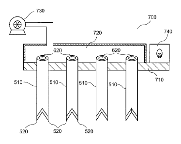
In a further exemplary embodiment of the present disclosure, an exemplary
apparatus 700 can be provided as shown in Fig. 7. The apparatus 700 can
include, e.g., a
plurality of tubes 510 affixed or mechanically coupled to a base 710. The
tubes 510 can be
provided in various configurations, e.g., in a linear array, or in any one of
various two-
dimensional patterns along the base 710. The number of tubes 510 provided in
the
exemplary apparatus 700 can be, for example, greater than five tubes 510, more
than about
10 tubes, or more than about 30 tubes 510.
An enclosure 720 may be provided in communication with proximal openings
620 of the tubes 510. The enclosure 720 can also be provided in communication,
e.g., with
a pressure source 730. For example, the pressure source 730 can include a pump
or a
deformable bulb or the like. The pressure source 730 can include, e.g., a
flexible
membrane provided in communication with the enclosure 720, such that an
elevated
pressure can be provided within the enclosure 720 when the membrane is
deformed. Such
configurations can facilitate applying pressure to the proximal openings 620
for removal
and/or insertion of the micrografts 120 that can be harvested in the tubes
510, as described
herein.
A vibrating arrangement 740 may optionally be provided in the apparatus 700.
The vibrating arrangement 740 can be mechanically coupled to the base 710
and/or the
tubes 510 to facilitate the insertion of the tubes 510 into the tissue or
matrix material for
harvesting or placement of micrografts 120. The vibrating arrangement 740 can
have an
amplitude of vibration in the range of about 50-500 jim, or between about 100-
200 wri.
The frequency of the induced vibrations can be between about 10 Hz and about
10 kHz, or
between about 500 Hz and about 2 kHz, or even about 1 kHz. Particular
vibration
parameters can be selected based on, e.g., the size, average spacing, and
material of the
tubes 510, the number of tubes 510 in the exemplary apparatus 700, and/or the
tissue being
treated. The vibrating arrangement 740 can include circuitry configured to
adjust the
amplitude and/or frequency of the vibrations.
--17--
CA 02739097 2011-03-30
WO 2009/146068
PCMJS2009/039114
The exemplary apparatus 700 can be used to simultaneously obtain a plurality
of the micrografts 120 in the plurality of the tubes 510. Exemplary procedures
for
obtaining and removing such micrografts 120 using the exemplary apparatus 700
can be
similar to the procedures described herein for obtaining single micrografts
120 using the
exemplary apparatus 500 shown in Figs. 6A-6C.
The vibration can also assist in severing tissue proximal to the distal end of
the
tubes 510 after they are fully inserted into the donor site 100. This can
facilitate separation
and/or extraction of the tissue portions within the tubes 510 from the donor
site 100. These
tissue portions can also be held by friction within the tubes 510 as the tubes
510 are
withdrawn from the donor site 100.
In further embodiments, the donor site tissue can be pre-cooled prior to
insertion of the tubes 510, e.g., using convective or conductive techniques
such as applying
a cryospray or contacting the tissue surface with a cooled object. Cooling of
the donor site
100 can reduce a sensation of pain when the tubes 510 are inserted into the
donor site
tissue 100, and can also make the tissue 100 more rigid and facilitate a more
accurate
severing of tissue portions (e.g., micrografts 120) by the tubes 510.
The positions and spacing of the tubes 510 in the exemplary apparatus 700 can
be determined, e.g., based on characteristics of the micrografts 120 to be
obtained, a
damage pattern to the donor site 100, and/or other factors as described herein
above. The
number of the tubes 510 provided in the exemplary apparatus 700 can be
selected based on
various factors. For example, a larger number of tubes 510 may be desirable to
allow more
micrografts 120 to be harvested simultaneously from a donor site 100. Such
exemplary
configuration can facilitate a more efficient harvesting process. A smaller
number of the
tubes 510 can be easer to insert simultaneously into the donor site tissue
100. Further, the
exemplary apparatus 500 having a very large number of the tubes 510 can be
difficult to
manufacture and/or maintain.
The harvested tissue portions can be deposited directly from the tubes 510
into
the biocompatible matrix material 210. The tubes 510 and tissue portions
contained
therein can be cooled before removal of the tissue portions. This can stiffen
the tissue
portions within the tubes 510 and make them easier to manipulate and position.
In a further embodiment, an apparatus can be provided that includes a
plurality
of substantially parallel blades. The ends of certain ones of the adjacent
blades can be
connected or closed off to provide, e.g., narrow rectangular openings between
adjacent
-- 18--
CA 02739097 2011-03-30
WO 2009/146068
PCMJS2009/039114
blades. Such an exemplary apparatus can be used, e.g., to form the tissue
strips 320 such
as that shown in Fig. 3C. Spacings, lengths, and other features of this
exemplary apparatus
can be selected based on factors similar to those described herein, e.g., for
the exemplary
apparati 500, 700.
In further exemplary embodiments of the present disclosure, the exemplary
methods and apparati described herein can be applied to other tissues besides
skin tissue,
e.g., internal organs such a s a liver or heart, and the like. Thus, grafts
can be formed for a
variety of tissues while producing little damage to a donor site and
facilitating rapid
healing thereof, while creating graft tissue suitable for placement at
recipient sites.
Example
An image of a distal end of an exemplary apparatus that includes two points is
shown in Fig. 8A. This apparatus is similar to the exemplary apparatus 500
illustrated,
e.g., in Fig. 5A. A further rotated image of this exemplary apparatus is shown
in Fig. 8B.
The exemplary apparatus was formed using a tube having an outside diameter of
about 1
mm, and an inside diameter of about 0.5 mm. The points or extensions were
formed by
grinding two opposite sides of the distal end of the tube at an appropriate
angle relative to
the axis of the tube. The angle used was about 30 degrees, although other
angles may also
be used. A beveled edge of the tube wall can be seen along the sides of the
points or
extensions. The shape of these points can facilitate insertion of the
apparatus into tissue of
a donor site and/or separation of a portion of micrograft tissue from the
donor site, as
described in more detail herein. For example, such micrografts can be
separated and
removed from the donor site by inserting and withdrawing the apparatus from
the donor
site tissue without rotating the tube along its axis.
Fig. 9 is an image of a plurality of micrografts obtained from a donor site of
ex
vivo skin tissue using the apparatus shown in Figs. 8A-8B. The micrografts are
elongated
and substantially similar in shape, although details of the shapes may be
somewhat
irregular. An upper portion of these micrografts includes epidermal tissue,
and the lower
portion of these micrografts include dermal tissue removed from the donor
site. The width
of these micrografts is slightly smaller than the internal diameter of the
tube shown in Figs.
8A-8B that was used to harvest them.
The micrografts shown in Fig. 9 were removed from the apparatus by inserting
the exemplary apparatus into donor site a plurality of times, until the tube
was filled with
--19--
CA 02739097 2016-02-24
88100-1
harvested tissue. Each subsequent insertion of the apparatus into the donor
site tissue then forced
the uppermost micrograft out of the proximal end of the tube, where it was
retrieved individually
for analysis. Such micrografts can also be removed by applying pressure to the
proximal end of the
tube containing the micrograft, to force it out of the distal end of the tube
as described herein.
The foregoing merely illustrates the principles of the present disclosure.
Various
modifications and alterations to the described embodiments will be apparent to
those skilled in the
art in view of the teachings herein. It will thus be appreciated that those
skilled in the art will be
able to devise numerous techniques which, although not explicitly described
herein, embody the
principles of the present disclosure.
--20--