Note: Descriptions are shown in the official language in which they were submitted.
CA 02739149 2011-05-05
AIR SEEDER TANK AND DISTRIBUTION APPARATUS
This invention is in the field of agricultural implements and in particular a
product tank
and distribution apparatus for an air seeder.
BACKGROUND
Air seeders typically include an implement frame mounted on wheels, with a
plurality of
furrow openers mounted on the frame. The furrow openers can be moved from a
raised
non-operative position to a lowered operating position where the furrow
openers engage
the ground and create furrows. Agricultural products such as seed and various
types of
fertilizer are carried in separate tanks which can be mounted on the implement
frame or
on a cart towed along with the implement frame.
The application rate of the various products varies significantly from as low
as about
three pounds per acre to 300 pounds per acre or more. In order to keep track
of the
amount of product remaining in each tank it is known to provide sight glasses
or low
level alarms to measure product remaining in the tank, or at least warn when a
tank is
approaching empty. Cameras are also sometimes used in the tank so the operator
can
visually monitor the product quantity, and it is further known to mount load
cells under a
tank and provide a readout of the weight of product in the tank. Present
product
containers for air seeders however, are typically are built with a number of
compartments
in a single tank assembly. The assembly thus contains a number of tanks
separated by
walls, and it is thus not possible to weigh the product in each tank, but only
the entire
tank assembly.
Metering devices dispense products from the tanks into one or more air streams
that carry
the products through a network of hoses and manifolds to the furrow openers
where same
are deposited in the furrows. Most modem air seeders have furrow openers that
deliver
seed to seed furrows and fertilizer to separate fertilizer furrows. These may
be totally
1
CA 02739149 2011-05-05
separate furrow openers mounted on separate shanks, such as mid row fertilizer
banding
furrow openers which are remote from the seed furrow openers, or combination
furrow
opener where a single shank supports a furrow opening tool that makes one
furrow for
seed and a separate furrow for fertilizer. There are also then two separate
distribution
networks, one delivering product from selected ones of the tanks to the seed
furrows, and
one delivering product from selected ones of the tanks to the fertilizer
furrows.
The terms "seed" and "fertilizer" are not meant restrictively, since in many
cases some
fertilizer is metered into the air stream carry the seed, and also in some
instances it may
be that fertilizer may be directed into the "seed" furrows, and vice versa if
conditions
warrant it. The terms "seed" and "fertilizer" are simply convenient to
differentiate the
two separate "runs" or air streams. Basically in an air seeder it is desirable
to be able to
direct agricultural product from any of the tanks into any of the available
air streams.
The wide range of application rates applies not just to total product but also
to the product
mix. When seeding canola for example the application rate of canola seed may
be three
pounds per acre while fertilizer is applied at 300 pounds per acre. It is
desirable then to
use a smaller product tank for canola seed, and direct the seed from that tank
to the seed
air stream for carriage to the seed furrows. On the other hand when seeding
peas for
example the application rate of pea seed may be 200 pounds per acre while
fertilizer is
applied at 50 pounds per acre, and it is then desirable to use one or more
larger product
tanks for pea seed, and direct the seed from those tanks to the seed air
stream for carriage
to the seed furrows. Thus the frequency of the need to stop and fill when one
tank is
empty can be reduced.
In a typical air seeder a metering roller, auger, or the like dispenses
product from each
tank into an air stream. A conduit or the like generally connects the air
stream to the top
of the interior of the tank to pressurize the tank so that there is no
pressure differential
between the tank and the air stream which would put back pressure on the
product as it is
2
CA 02739149 2011-05-05
being metered into the air stream. This requires that the lid on the tank fill
opening is
sealed and clamped when closed.
The air stream carries the product through a primary hose to a manifold where
the air
stream and product is divided and directed into multiple secondary hoses
connected to the
manifold outlet ports. In some arrangements each secondary hose connects into
a further
manifold and the air stream is divided again into further final hoses leading
to each
furrow opener. It is desired to have an equal product quantity in each of the
secondary
hoses to provide equal product quantity in each of the final hoses, however
the secondary
and final hoses are typically of varied lengths. A longer hose will exert more
back
pressure and resistance to flow from the manifold compared to a shorter hose,
and so air
and product flows from the manifold are unequal as the longer hoses have a
reduced flow
and the shorter hoses have increased flow. In addition, manifolds of various
sizes are
also often used on one air seeder, for example some of the manifolds may have
six
outlets, and some eight outlets, to conveniently match the number of openers
on the air
seeder. As a result different pressures in the different sized manifolds again
contribute to
uneven distribution to the furrow openers.
Wider air seeders require more furrow openers and therefore more manifolds.
Thus it is
also known to divide product by delivering product from different sections
along the
length of a continuous meter roller into different air streams in different
primary hoses,
and then into manifolds. With this system, it is desirable to have the air
pressure at the
metering area to be the same for all primary hoses, so that reverse air flow
through the
meter won't affect the metered rate in one primary hose compared to another.
To help
achieve this balanced pressure all primary hoses are typically the same
length.
Dividing at the meter roller reduces the number of manifolds required, but
with a
continuous meter roller divided into sections, sealing between sections is
problematic and
air and product can cross over from one meter section to another section,
reducing the
desired uniformity of metered product distribution to each opener.
3
CA 02739149 2011-05-05
In order to reduce overlap in very wide air seeders it is further desirable to
be able shut
off the supply of product to sections of the air seeder. It is known to use
gate
mechanisms for shutting off flow of product from the tank to a section of a
continuous
meter roller however these gate type shut off mechanisms result in product
flow onlotf
lead times that are difficult to deal with. The product between the gate and
the meter
roller continues to be metered until it is used up, even after the gate is
closed. For
products that are metered at a low rate, it takes a significant time for the
product to stop
flowing to the furrow openers. Again for these products, when the gate is re-
opened it
takes some time for the meter to turn enough to start dropping product into
the air stream.
Such a gated meter is disclosed for example in United States Patent Number
7,690,440 to
Dean.
In some air distribution systems gate mechanisms are also used to direct the
product from
one metering device to either the seed air stream or the fertilizer air
stream. Again
scaling such gates is difficult and air can pass between the seed and
fertilizer air streams,
especially when the speed and pressure of one air stream is significantly
greater than the
other. When seeding low rates of light seed like canola, it is desirable to
have a low air
speed and pressure, while often at the same time it is desired to apply a high
rate of
fertilizer which requires a high air speed and pressure to carry the high
product volume
through the system. When two different pressures and air speeds enter such a
gated meter
system, the air crosses over from the fertilizer to the seed side resulting in
increased air
speed on the seed air stream and reduced air speed in the fertilizer air
stream.
SUMMARY OF THE INVENTION
It is an object of the present invention to provide an air seeder product tank
and
distribution apparatus that overcomes problems in the prior art.
4
CA 02739149 2011-05-05
In a first embodiment the present invention provides an air seeder
distribution apparatus
comprising a seed product tank and a fertilizer product tank mounted on a
frame for
movement along the ground with an air seeder, and a plurality of seed metering
devices
mounted on the seed product tank, and a like plurality of fertilizer metering
devices
mounted on the fertilizer product tank. Each metering device comprises a feed
roller
rotatably mounted in a housing and operative, when the feed roller thereof is
rotating, to
dispense a product flow from the product tank. A control is operative to
selectively start
and stop rotation of the feed roller of each metering device. A manifold set
comprises a
like plurality of product manifolds, each product manifold having an input
port and a
plurality of output ports. A like plurality of supply hoses each carries an
air stream and
extends under one of the plurality of seed metering devices and under one of
the plurality
of fertilizer metering devices. An output end of each supply hose is connected
to the
input port of one of the plurality of product manifolds in the manifold set.
The product
flow from each metering device can be directed through a feed conduit into the
supply
hose extending thereunder.
In a second embodiment the present invention provides an air seeder tank and
distribution
apparatus comprising a product tank with a single compartment for carrying a
single
product, the product tank mounted on a frame for movement along the ground
with an air
seeder. A weight sensor is mounted between the product tank and the frame such
that a
weight of the product tank is displayed on a weight indicator. A supply hose
extends
under the product tank and is supported on the frame independent of the
product tank. A
pressurized air source is connected to the supply hose and directs an air
stream into the
supply hose. A metering device is operative to dispense product from the
product tank
and a flexible feed conduit is connected at an upper end thereof to an output
of the
metering device and connected at a lower end thereof to the supply hose such
that
product dispensed from the metering device is directed into the supply
conduit.
In a third embodiment the present invention provides an air stream balancing
apparatus
for an air seeder. The apparatus comprises an enclosure with a plurality of
output ports
CA 02739149 2011-05-05
and an input port connected to receive an air stream from a pressurized air
source of the
air seeder into the enclosure, and a plurality of output conduits. Each output
conduit is
connected at an input end thereof to an output port through a connection
orifice to receive
the air stream from the enclosure, and is connected at an output end thereof
to a
downstream. element of a distribution network of the air seeder. The cross-
sectional area
of the connection orifices is unequal.
In a fourth embodiment the present invention provides a remotely controlled
lid apparatus
for a fill opening on a product tank of an air seeder. The apparatus comprises
a lid
movably attached to the product tank adjacent to the fill opening such that
the lid can
move from an open position, where the fill opening is open for filling the
product tank, to
a closed position where the lid covers the fill opening. A seal is operative
to provide a
seal between the lid and edges of the fill opening, and an actuator is
operative to move
the lid between the closed position and the open position, and operative to
exert a
downward force on the lid against the seal when the lid is in the closed
position.
The present invention provides a plurality of completely individual and
isolated meter
devices, with independent drives, on a single tank. Each meter device can
dispense
independently from the tank to an individual manifold, and the metering rate
for each
metering device can be set differently for different sized manifolds. For
example a meter
device feeding a manifold with six outlets would dispense a rate that is 75%
of a meter
device feeding a manifold with eight outlets. With the use of isolated meter
devices, the
air stream pressure in the primary hoses from the meter devices to the
manifolds can be
set differently on different hoses to better suit the manifold size and hose
length to the
manifold. Product flow to individual manifolds can also be shut off and on
instantly by
disengaging the individual drive of a metering device. Further, the seed air
streams and
tanks are completely isolated from the fertilizer air streams and tanks, so
there is no
danger of air and/or product crossing over. As a result, largely different air
speeds and
pressures can be successfully used in the seed and fertilizer air streams.
6
CA 02739149 2011-05-05
The present invention further provides a simple and economical apparatus for
accurately
monitoring the product weight in an air seeder product tank during operation
and also
while filling the tank.
The present invention further provides a remotely controlled lid for a product
tank fill
opening. Conveniently the system uses hydraulic force from the implement
hydraulic
system, typically from the hydraulic conduits feeding the hydraulic drive fan,
to exert a
constant force against the compressive seal member. The downward force on the
lid
automatically compensates for structural changes over time by uniformly
applying a
downward force when in the seeding mode, thereby ensuring a good seal and
reduced
risk of air leaking from the tank and bleeding pressure from the air stream.
The present invention further provides a system for balancing the flow of air
and
agricultural products in each conduit of an air seeder distribution network. A
choke gate
on manifold outlets is adjustable for the purpose of balancing the back
pressure from
hoses of different lengths and thereby increases the uniformity of product
flow from the
manifold into each hose. The choke gate adjustment increases the back pressure
on
shorter output hose lengths to match that of longer output hoses, and is
typically only set
once to match output hose length variation requirements. The same choke system
can be
used to balance overall flow in primary hose to a given manifold where
multiple
manifolds and primary hoses are used. When multiple manifolds are used, the
air and
product flow to the individual manifolds may also vary due to variations in
primary hose
length. Again, longer hoses result in higher back pressure and lower flow. By
choking a
complete manifold on shorter primary hose lengths, a balanced air and product
flow can
be achieved. A similar system can be used at the plenum where a fan output is
divided
into numerous supply hoses.
7
CA 02739149 2011-05-05
DESCRIPTION OF THE DRAWINGS
While the invention is claimed in the concluding portions hereof, preferred
embodiments
are provided in the accompanying detailed description which may be best
understood in
conjunction with the accompanying diagrams where like parts in each of the
several
diagrams are labeled with like numbers, and where:
Fig. is a schematic top view of an embodiment of an air seeder tank and
distribution
apparatus of the present invention;
Fig. 2 is a schematic side view of the embodiment of Fig. 1;
Fig. 3 is a perspective front view of an embodiment of a metering apparatus of
the
present invention;
Fig. 4 is a side view of the drive of the metering apparatus of Fig. 3;
Fig. 5 is a sectional side view of the metering apparatus of Fig. 3;
Fig. 6 is a schematic top view of the fan plenum and attached supply hoses of
the
embodiment of Fig. 1;
Fig. 7 is a schematic end view of the fan plenum and attached supply hoses of
Fig. 6;
Fig. 8 is a schematic end view showing the alignment and misalignment of the
plenum
output ports and the supply hoses to change the cross-sectional area of the
connection
orifice;
8
CA 02739149 2011-05-05
Fig. 9 is a perspective view of a manifold apparatus of the present invention
where the
size of the connection orifice at the output ports can be adjusted by moving
gate flaps
to balance the back pressure at all output ports;
Fig. 10 is a schematic side view of an alternate manifold apparatus with a
choking
sheet installed inside the manifold to reduce the size of the connection
orifice at some
selected ones of the output ports to balance the back pressure at all output
ports;
Fig. 11 is a schematic top view of the manifold apparatus of Fig. 10;
Fig. 12 is a schematic view of a choking sheet for use with the apparatus of
Fig. 10,
with the sheet laid out flat.
Fig. 13 is a schematic sectional side view of an embodiment of a remotely
controlled
tank lid apparatus of the present invention with the lid in the closed
position;
Fig. 14 is a schematic sectional side view of the remotely controlled tank lid
apparatus
of Fig. 13 with the lid in the open position, and showing an alternate
hydraulic
connection.
DETAILED DESCRIPTION OF THE ILLUSTRATED EMBODIMENTS
Figs. 1 and 2 schematically illustrate an embodiment of an air seeder tank and
distribution apparatus 1 of the present invention for use with an air seeder.
Commonly
such air seeders will have two to four different tanks for carrying
agricultural products to
be applied on a filed. Conventionally, these tanks are generally formed by
dividing a
large container into separate tanks by providing walls to form separate
compartments. In
contrast, the illustrated apparatus 1 is shown with three product tanks 3,
each with a
single compartment for carrying a single product, and each mounted separately
to a frame
for movement along the ground with an air seeder. In the illustrated apparatus
1, the
9
CA 02739149 2011-05-05
frame 5 is mounted on wheels 7 to form an air seeder cart towed behind the air
seeder
implement 9 which carries the furrow openers 11. Alternatively, as is known in
the art,
one or more of the product tanks can be carried on the air seeder implement 9.
A weight sensor 13 is mounted between each product tank 3 and the frame 5 such
that a
weight of each product tank 3 is displayed on a weight indicator 15. The
weight sensor
13 is schematically illustrated as a common load cell under each corner of
each tank 3,
with leads from the load cells under each tank 3 to the weight indicator 15,
however
other weight sensors as are known in the art are contemplated for use as well.
The illustrated weight indicator 15 is located adjacent to the frame 5 visible
to an
operator filling a product tanks with product. A readout on the weight
indicator 15 shows
the weight of each tank 3. While a similar indicator could be provided in the
cab of the
tractor so as to be visible to the operator during field operations, these
indicators are
costly and the illustrated apparatus I instead uses an economical camera 17
focused on
the weight indicator 15 and transmitting a view of the weight indicator to a
display 19
visible to the operator. The weight indicator 15 and camera 17 could be
enclosed in a
sealed enclosure 21 to prevent dust from obscuring the camera and to protect
the
equipment. The enclosure 21 could have a transparent wall, or could have a lid
that
opens so the operator can see the weight indicator 15 when filling the product
tanks 3.
A plurality of supply hoses 23 extend under the product tanks 3 from the rear
end to the
front end of the frame 5. The supply hoses 23 are supported on the frame 5
independent
of the product tanks, and a pressurized air source, illustrated as fans 25, is
connected to
each supply hose and directs an air stream into each supply hose 23.
Metering devices 27 are operative to dispense products from each product tank
3, and a
flexible feed conduits 29 is connected at an upper end thereof to the output
of each
metering device 27 and is connected at a lower end thereof to one of the
supply hoses 23
CA 02739149 2011-05-05
such that product dispensed from each metering device 27 is directed into one
of the
supply conduit 23.
Thus the tanks 3 and supply hoses 23 are fixed to the frame 5 independently
and are
connected only by the flexible feed conduits 29 which will transfer negligible
force from
the tanks 3 to the supply hoses 23, and therefore not affect the weight of the
tanks 3 as
sensed by the weight sensors 13.
The illustrated apparatus I also shows a microprocessor 31 operative, during
field
operations, to periodically receive weight information from the weight
indicator 15 and
compare actual product usage with a target product usage input by the
operator. The
microprocessor will be programmed with the width of the air seeder implement 9
and will
receive ground speed and travel distance information and be able to compare
the actual
weight of product applied over a known field area with the desired application
rate, and
could be operative to display the difference to the operator, or could be
programmed to
control the metering devices 27 to adjust actual product usage to the target
product usage-
The illustrated air seeder tank and distribution apparatus t has three
separate metering
devices 27, as illustrated in Figs. 3 - 5, under each product tank 3. Each
metering device
27 comprises a feed roller 33 rotatably mounted in a housing 35. Each metering
device is
operative, when the feed roller 33 thereof is rotating, to dispense a flow of
agricultural
product 37 from the product tank 3 into a supply hose 23 extending thereunder.
A
control is operative to selectively start and stop rotation of the feed roller
33 of each
metering device 27.
Each supply hoses 23 extends under a corresponding metering device 27 on each
product
tank 3. The fan 25 directs an air stream AS through the supply hoses 23, each
of which is
connected at an output end thereof to the input port of a product manifold 39.
The air
stream carries the dispensed product through the supply hose to the manifold
39. The
manifold 39 divides the air stream AS and the agricultural products entrained
therein, into
11
CA 02739149 2011-05-05
final hoses 41, each connected to an output port of the manifold 39 to deliver
the air
stream AS and products to a furrow 43 made by a furrow opener 11.
In the illustrated apparatus 1, the housing 35 of each metering device 27 is
mounted
under an open bottom 45 of the product tank 3 such that the right, middle, and
left
metering devices 27R, 27M, and 27L are oriented side by side across the open
bottom 45
of each product tank 3.
In the illustrated apparatus 1, the three product tanks 3 are mounted from
along the length
of the frame 5, and a seed supply hose 23S and a fertilizer supply hose 23F
extend side
by side to form a supply hose pair 23P extending under each metering device 27
from the
rear portion of the frame 5 to a front portion of the frame 5 as illustrated.
Thus right,
middle, and left supply hose pairs 23PR, 23PM, 23PL extend under the
corresponding
right, middle, and left metering devices 27R, 27M, and 27L of each product
tank 3, and
then forward to the manifold sets mounted on the furrow opener carrying
implement 9 of
the air seeder. As described in more detail below, the flow of material
dispensed from
each metering device 27 can be directed into either the seed hose 23S or the
fertilizer
hose 23P of the hose pair 23P running under the device and be delivered to a
corresponding manifold 39S or 39F connected to the supply hose.
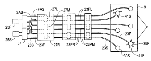
As can be seen in Fig. 1, the seed air stream SAS carried through the seed
supply hose
23S is provided by the seed fan 25S while the fertilizer air stream FAS
carried through
the fertilizer supply hose 23F is provided by the fertilizer fan 25F. Output
ends of each
seed hose 23S are connected to one of the seed manifolds 39S of the seed
manifold set,
for example mounted across the rear portion of the implement 9 as shown in
Fig. 1, while
output ends of each fertilizer hose 23F are connected to one of the fertilizer
manifolds
39F of the fertilizer manifold set mounted across the front portion of the
implement 9.
Final hoses 41S connected to the output ports of the seed manifolds 39S
deliver product
into seed furrows 43S made by the furrow openers 11, and final hoses 41F
connected to
12
CA 02739149 2011-05-05
the output ports of the fertilizer manifolds 39F deliver product into
fertilizer furrows 43F
made by the furrow openers 11.
Thus the apparatus 1 has a seed distribution network carrying the seed air
stream SAS
and comprising the seed fan 25S, seed supply tubes 23S, a set of seed
manifolds 39S, and
final hoses 41S and a completely separate fertilizer distribution network
carrying the
fertilizer air stream FAS and comprising the fertilizer fan 25F, fertilizer
supply tubes 23F,
a set of fertilizer manifolds 39F, and final hoses 41 F. Agricultural products
from each
tank 3 can be metered into either one of the distribution networks, such that
any product
tank 3 can be used to carry either seed or fertilizer, and the product with
the highest
application rate can be carried in the largest product tank 3. Similarly the
same product
may be carried in two separate tanks 3, and a portion of the required
application rate for
that product would be metered from each tank into the appropriate supply
hoses.
Again reference to "seed" and "fertilizer" is only for convenience to
differentiate one
distribution network from the other, as typically one of the pair of supply
hoses will carry
seed and the other will carry fertilizer, but either supply hose could be
carrying either
product.
For illustration purposes the illustrated apparatus 1 shows three metering
devices 27,
however for the typical wider air seeders presently common there will more
commonly
be from six to ten metering devices 27 attached along the bottom of each tank
3 and
corresponding supply hose pairs 23P extending thereunder. Since on each
product tank 3
there is one metering device 27 for each manifold, a wider implement will
require more
manifolds and therefore more metering devices.
The same number of metering devices 27 is mounted on each product tank 3, and
in each
of the seed and fertilizer distribution networks, the number of supply hoses
23 and
manifolds 39 is the same as the number of metering devices on each product
tank 3.
13
CA 02739149 2011-05-05
With the control operative to start and stop rotation of the feed roller 33 of
each metering
device 27 independently of the feed rollers of the other metering devices,
delivery of
agricultural products to each manifold can be started and stopped
independently of the
other manifolds. The control will typically be configured to substantially
simultaneously
start and stop rotation of the feed rollers 33 of all metering devices 27
dispensing
agricultural products into a selected supply hose 23 to stop all product flow
to the
corresponding manifold 39 fed by the supply hose. By arranging the furrow
openers 11
fed by each manifold 39 in sections in order across a width of the implement
9, delivery
of agricultural products to those sections of furrow openers 11 passing over
previously
seed ground can be stopped.
In the illustrated metering devices 27, a rotating driveshaft extends across
the metering
devices 27 and is operative to rotate the metering devices. The control is
operative to
start and stop rotation of the feed roller 33 of each metering device 27 by
engaging and
disengaging a shaft 47 of each feed roller 33 with the driveshaft.
Each metering device 27 comprises a feed roller 33, as seen in the cut away
view of Fig.
4, mounted on a roller shaft 47. As seen in Fig. 4 driven sprocket 49 is
mounted to the
same shaft 47. Drive sprocket 51 is mounted to a drive shaft 53 extending
across the
open bottom 45 of the product tank 3 that is rotated by a hydraulic motor,
electric motor,
ground drive, or the like at a speed controlled to dispense whatever
application rate is
desired. Middle sprocket 55 is rotatably mounted to drive arm 57 which is
pivotally
mounted to the metering device 27 at arm pivot axis APA. Extendable actuator
59 is
connected to the drive arm 57 such that retracting the actuator 59 moves the
middle
sprocket 55 down to mesh with the front and driven sprockets 49, 51, such that
the
rotating drive sprocket 51 causes the driven sprocket 49, the roller shaft 47,
and the feed
roller 33 to rotate and dispense product.
Thus the drive sprocket 51 is mounted on the drive shaft 53 adjacent to each
metering
device 27, and the driven sprocket 49 is mounted on the shaft 47 of each feed
roller 33,
14
CA 02739149 2011-05-05
and the middle sprocket 55 is movable from an engaged position, where the
middle
sprocket 55 engages, as illustrated in Fig. 4, the drive sprocket 51 and the
driven sprocket
49 to rotate the feed roller 33, and a disengaged position where the middle
sprocket is
above and disengaged from the drive and driven sprockets 51, 49. The actuator
59 is
operative to move the middle sprocket 55 between the engaged and the
disengaged
positions. The control is operative to activate the actuator 59, and is
typically provided
by a manual signal from the operator or by a position mapping system, such as
a global
positioning system, which determines that the particular metering device 27
should be on
or off.
Retracting the extendable actuator 59 moves the middle sprocket 55 up such
that the
driven sprocket 49, and thus the feed roller 33, stop rotating and product
flowing into the
hose 23 stops immediately. Similarly when the actuator 59 is extended, the
sprocket 49
and feed roller 33 begin rotating and product immediately begins to flow
again. This
very quick response time provides improved accuracy when shutting down
sections of an
air seeder to avoid overlap. Each metering device 27 on each tank 3 can be
controlled
independently of any other metering device 27.
It is contemplated that electric clutches or extendable actuators, or a
hydraulic cylinder
with pressurized oil supply, or any like actuator could be used but the
actuator 59 is very
conveniently and economically provided by an extendable pneumatic cylinder
supplied
by compressed air from a compressor mounted on the tractor or air seeder.
These
pneumatic cylinders are fast acting, which also increases the accuracy of the
on/off
switching times, and can be controlled easily with electrically activated
solenoid valves.
The drive shaft 53 extending across the open bottom 45 of the product tank 3
is made up
of a drive shaft section 53A on each metering device 27. The sections 53A of
adjacent
metering devices 27 are connected to each other by pins 61 extending laterally
from the
drive sprocket 51 on one metering device 27 and engaging lugs 63 on a coupler
65
attached to the end of the drive shaft section 53A on the adjacent metering
device 27.
CA 02739149 2011-05-05
The drive shaft 53 requires only low torque and low speed and this "loose"
connection of
lugs 63 and pins 61 provides for smooth transfer of rotation from one drive
shaft section
53A to the next while allowing considerable tolerances in placement. This
connection
also allows any metering device 27 to be removed from a location between
adjacent
metering devices on each side thereof simply by removing the bolts mounting
the
metering device to a meter mounting channel 67, by rotating the drive shaft
section 53A
so that the pins 61 pass between the lugs 63 on the adjacent coupler 65, and
sliding the
metering device 27 forward. The illustrated meter mounting channel 67 attaches
to the
open bottom 45 of the product tank 3 to facilitate mounting the metering
devices 27 to the
tank 3.
Thus any metering device 27 can be removed for service or repair. To prevent
product
from flowing out when the metering device is removed a blocking plate 69 can
be
inserted into a slot 71 defined in the meter mounting channel 67 above each
metering
device 27. This feature of the present metering system also allows the same
tank 3 to be
used for a wide variety of air seeder widths. Where a narrower air seeder is
used, fewer
manifolds 39 are required and thus also fewer metering devices 27. The tank
can then be
configured to accept the maximum contemplated number of metering devices 27,
and
where fewer metering devices are used, a blocking plate 69 is inserted and a
sloped roof
member 73 can be placed above the blocking plate 69, as outlined in dotted
lines in Fig.
3, such that product in the tank flows to the adjacent metering device 27. The
metering
devices 27 will he placed adjacent to each other starting at the driven end of
the
driveshaft 53, until the desired number is in place. The drive shaft sections
53A of
adjacent metering devices 27 will thus engage and drive the feed rollers 33.
Alternatively
a drive shaft extension could be inserted across a gap representing an omitted
metering
device 27.
The slots 71 are covered by a flexible magnetic sheet 75, similar to a fridge
magnet, when
the apparatus I is operating to prevent the escape of pressurized air from the
supply
conduits 23 up through the metering device 27.
16
CA 02739149 2011-05-05
Conveniently as well the driven and drive sprockets 49, 51, can be changed to
change the
dispensing rate of one metering device relative to an adjacent metering
device. In fact in
the illustrated metering device 27, the driven and drive sprockets 49, 51 can
be
conveniently interchanged. Where for example the illustrated configuration
with the
large sprocket driving and the smaller sprocket driven supplies desired
application rate to
a manifold 39 with eight outlets, reversing the sprockets 49, 51 so the
smaller one is the
drive sprocket and the larger sprocket is the driven sprocket provides a
dispensing rate
that is 75% of the desired application rate, which is ideal to supply a
manifold 39 with six
outlets, so that the same amount of product flows in each of the six final
hoses 41 as
flows in each of the eight final hoses 41.
The outlet of each metering device 27 is connected to the top end of a length
of flexible
feed conduit 29. The supply hose pairs 23P are supported on the frame 5 of the
air seeder
on supports 77 under the metering devices 27 and a connector hose 79 extends
up from a
Y-fitting in each supply hose 23 of the hose pair 23P. A switching mechanism
is
operative to connect a lower end of the feed conduit 29 to an upper end of a
selected one
of the Y-fittings in the supply hoses 23S, 23F, and is operative to seal the
upper end of
the other unselected one of the Y-fittings.
To provide the switching mechanism in the illustrated embodiment, the top end
of each
connector hose 79 is fixed to a transition plate 81 with openings
corresponding to the
open top ends of the connector hoses 79. A switching plate 83 is urged
downward
against the top of the transition plate by a bias force BF exerted by a spring
85 and a seal
between the transition plate 81 and the switching plate 83 prevents
pressurized air from
leaking from the supply hoses 23.
The lower end of the flexible feed conduit 29 is connected to an opening in
the switching
plate 83 such that product can pass from the conduit 29 through the switching
plate 83
and into an aligned one of the connector hoses 79. Fig. 3 illustrates the feed
conduits 29
17
CA 02739149 2011-05-05
aligned with connector hoses 79 leading to fertilizer supply hoses 23F. The
switching
plate 83 may also he lifted somewhat against the bias force BF and rotated
half a turn to
align the flexible feed conduit 29 with the other of the connector hoses 79 to
deliver
product to the seed supply hose 23S. Thus the metering devices 27 on each tank
can be
connected to either of the supply hoses 23S, 23F. The switching plate 81 can
also be
turned one quarter turn to direct the product dispensed into a container to be
weighed for
calibration purposes.
With the use of isolated meter systems for each product tank 3, the air
pressure in the
supply hoses 23S, 23F can be set differently to better suit application rates.
It is also
contemplated that an air gate could be introduced at the inlet to a supply
hose 23 so air
pressure could be adjusted for example, in one fertilizer supply hose 23F
compared to an
adjacent fertilizer supply hose 23F to compensate for varying supply hose
length,
manifold size, etc. so long as the pressure differential is not so high as to
leak significant
amounts of air up through the metering device 27 on the higher pressure hose
through the
product 37 in the tank 3 to the lower pressure hose.
The disclosed metering system thus has significant advantages. By using
completely
individual meter sections to match the number of manifolds, gearing or meter
speed can
be set differently for different primary runs to balance the product
requirement to match
the different manifold sizes being used. Product flow to individual manifold
sections can
be shut off and on instantly by disengaging the individual drive. The seed
runs and tanks
are completely isolated from the fertilizer runs and tanks, so there is no
danger of air
and/or product crossing over. As a result, largely different air speeds and
pressures can
be successfully used.
When seeding with air conveying systems, such as apparatus 1, each supply hose
23
feeds product to a manifold 39. The manifold 39 splits the product into
multiple output
ports and into final hoses 41 connected to these ports. When the resistance to
flow at
each outlet port, or the "back pressure", is substantially equal, the air
stream entering the
18
CA 02739149 2011-05-05
manifold 39, and the agricultural products entrained therein, flows out of the
manifold
substantially equally through each port, as is desired to deliver equal
amounts of product
to each furrow 43.
When the final hoses 41 are of varied lengths, it introduces a variation in
product flow
from the manifold 39. The longer hoses have a higher back pressure at the
manifold
while the shorter hoses have a lower back pressure. The longer hoses therefore
have a
reduced product amount flowing therethrough and the shorter hoses have
increased
product flow.
The present invention therefore provides an air stream balancing apparatus for
an air
seeder, as schematically illustrated in Figs. 6 - 8. An enclosure, illustrated
as the plenum
87 of the apparatus 1, has a plurality of output ports 89 and an input port
91connected to
receive the air stream AS from the fan 25. The input end, illustrated as a
flange 93, of an
output conduit, illustrated as supply hose 23 of the apparatus 1, is connected
to each
output port 89 through a connection orifice 95 to receive the air stream AS
from the
plenum 23. An output end of each supply hose 23 is connected to a downstream
element
of the distribution network of the air seeder, as described above.
Depending on the configuration of the distribution network downstream along
each
supply hose, the back pressure at the output ports 91 can vary significantly.
In order
then to balance the air flow into each supply conduit, a desired cross-
sectional area of
each connection orifice 95 is determined by determining a pressure of the air
stream AS
in each supply hose 23 and selecting the cross-sectional area of each
connection orifice
95 to equalize the pressure of the air stream AS in each supply hose, such
that the cross-
sectional area of the connection orifices 95 is unequal.
For example where a long supply hose 23 is connected to a first output port 89
through a
first connection orifice 95, and a short supply hose 23', with a length less
than that of the
long supply hose 23, is connected to a second output port 89' through a second
19
CA 02739149 2011-05-05
connection orifice 95', the cross-sectional area of the first connection
orifice 95 is greater
than the cross-sectional area of the second connection orifice 95', as
schematically
illustrated in Fig. 8.
In Figs. 6 - 8 the input end of the supply conduit 23 comprises a flange 93
connected to a
wall of the plenum 87 over the output port 89 by fasteners 97 through
elongated apertures
99 in the flange 93, as illustrated, or in the plenum wall. Alignment of the
input end of
supply hose 23 and the output port 29 can be adjusted to vary the cross-
sectional area of
the connection orifice 95. Fig. 8 schematically illustrates the first
connection orifice 95
where the output port and the interior of the supply conduit are aligned and
the first
connection orifice 95 has an area equal to the entire circle indicated. The
output port and
the interior of the supply conduit are out of alignment to create the second
connection
orifice 95' with a cross-sectional area that is smaller by the shaded area A
in Fig. 8.
A similar air stream balancing apparatus is illustrated in Fig. 9, where the
enclosure is
one of the manifolds 39 of the apparatus 1. Again the size or cross-sectional
area of
certain of connection orifices at the manifold output ports 101 compared to
others is
reduced so that back pressure at the manifold 39 is equal at all output ports
101 regardless
of the length of the final hoses, the size of a further manifold being fed, or
any other
condition farther downstream. It is contemplated that manifolds could be
manufactured
with outlet ports 101 that vary slightly in size so that a whole network from
fan to furrow
opener could be tuned to accommodate designed hose lengths and manifold sizes,
thus
increasing the available design options rather than is now the case where the
output ports
of a manifold are all the same size. Alternatively, the invention provides for
adjusting the
back pressure at manifolds 39 to equalize back pressure at each outlet port
101, as was
done with the plenum 87 described above.
In the manifold 39 of Fig. 9, the size of the cross-sectional area of the
connection orifice
at the output ports 101 can be adjusted to balance the back pressure at all
output ports
101. A supply hose 103 is connected to bring an air stream, with agricultural
products
CA 02739149 2011-05-05
entrained therein, into the manifold 39. The manifold 39 includes a top cover
which is
open for illustration. Six output ports 101 are equally spaced about the
periphery of the
manifold 39 as in the prior art. A gate flap 105 is attached above each output
port 101 by
a fastener 107 extending through an elongated vertical slot in the wall of the
manifold 39
and wing nut 111 threaded onto each screw 107. The gate flap 105 can thus be
moved up
and down by positioning the screw 107 up or down along the slot, and the
position of the
gate flap 105 can be determined by looking at the exterior of the manifold 39
to see
where the screw 107 is in the slot. The gate flap 105 can thus cover a greater
or lesser
portion of the output port 101 and thus vary the cross-sectional area of the
connection
orifice.
When initially setting up an air seeder, the back pressure on each output port
101 can be
measured and the gate flaps 105 moved up and down to equalize the back
pressure at
each output port 101. Product can be conducted through the manifold and
measured at
each final hose output to check that the distribution is equal.
In some cases an air seeder may have more than one manifold size to
conveniently match
the number of openers on the seeder. The same air balancing system can be used
to
decrease the amount of product flow to the smaller manifolds by reducing the
size of, or
choking, all. the runs a small amount while also varying the choke amount for
secondary
hose lengths.
In systems where there is a first manifold dividing product to be fed into a
second
manifold for further division, so long as the back pressure at each output
port of the first
manifold is substantially equal, product will be evenly divided in that
manifold, and so it
is then required to equalize back pressure at outlets in each downstream
second manifold
to similarly equalize distribution from the second manifold. In such systems
it is further
contemplated that that an entire downstream second manifold could be choked
somewhat
to equalize back pressure at the output ports of a first manifold feeding a
plurality of
second manifolds.
21
CA 02739149 2011-05-05
Figs. 10 -- 12 schematically illustrate an alternate manifold 39' with a
choking sheet 113,
illustrated in Fig. 12, installed against the inside surface of the circular
manifold wall
117. The choking sheet l l3 includes recesses 115 configured such that when
installed in
the manifold 39', the recesses are substantially aligned with top sides of the
output ports
101 in the manifold wall. The choking sheet 113 is made from a flexible
plastic or metal
sheet material so same can be wrapped around the inside surface of the
manifold wall
117, where same is held in position by notches 119 in support members 121
attached to
the inside surface of the manifold wall 117.
The size of the recesses is selected to reduce the size or cross-sectional
area of the
connection orifice 95 at selected output ports 101 by blocking a top portion
thereat as
shown at recess 115A, and to leave certain other selected output ports
completely open,
as shown at recess 115B. The size of the recesses 115 is selected to provide
choking of
some output ports 101, such as where a shorter final hose provides reduced
back pressure,
relative to others such as where a longer output hose provides increased back
pressure, so
that the back pressure at each output port 101 is substantially the same. The
size of the
recesses 115 in the choking sheet 113 can be calculated when designing the
machine for
known hose lengths attached to known outlet ports. The recesses 115 can be
increased in
size if necessary to reduce choking if back pressure measurements during
installation
warrant by filing the edge of the choking member that forms the recess 115.
Instead of using a flat sheet, a ring with the recesses along a bottom rim
thereof could be
configured to slide down into the manifold against the inner surface of the
manifold wall.
The balancing system, and the apparatuses for practicing the method, provide
for greater
uniformity in distribution of product to the furrow openers. Once the choke
setting is
determined and set it should remain the same and not need adjustment unless
the hose
configuration changes.
22
CA 02739149 2011-05-05
Figs. 13 and 14 schematically illustrate a remotely controlled lid apparatus
150 for a
product tank till opening 151 of a product tank 3 of the apparatus I using a
hydraulic
cylinder 153 powered from the implement hydraulic system. The apparatus 150
comprises a lid 155 movably attached to the product tank 3 adjacent to the
fill opening
151 such that the lid 155 can move from an open position shown in Fig. 14,
where the fill
opening 151 is open for filling the product tank 3, to a closed position shown
in Fig. 13
where the lid 151 covers the fill opening 151. A seal 157 is operative to
provide a seal
between the lid and edges of the fill opening, and an actuator, provided in
the illustrated
apparatus 150 by hydraulic cylinder 153, is operative to move the lid 155
between the
closed position and the open position, and operative to exert a downward force
F on the
lid 155 against the seal 157 when the lid 155 is in the closed position.
In illustrated apparatus 150, the fan 25 is operative to create a pressurized
air stream to
carry agricultural products from the product tank, as described above, and an
inside of the
product tank 3 is connected to the air stream to equalize pressure between the
inside of
the product tank 3 and the air stream during operation so that agricultural
products can he
accurately dispensed by the metering devices. The fan 25 is driven by a
hydraulic motor
connected by a fan hydraulic conduits 159 to the pressurized hydraulic fluid
source 161.
An increase in hydraulic pressure in the fan hydraulic conduits 159 causes an
increase in
fan speed and an increase in a pressure of the air stream, and an increase in
the downward
force F on the lid 155 against the seal 157.
In the illustrated apparatus 150, an arm 163 is pivotally attached at a mid-
point thereof to
the product tank about a pivot axis PA, and the lid 155 is a pivotally
attached at a lid end
of the arm 163. An end of the hydraulic cylinder 153 is pivotally attached at
an opposite
cylinder end of the arm 163 such that activating the cylinder 153 to move the
cylinder
end of the arm 163 upward causes the lid 155 to move down against the seal
157, and the
upward force on the cylinder end of the arm 163 exerts the downward force F on
the lid
155 against the seal 157.
23
CA 02739149 2011-05-05
In the apparatus 150 illustrated in Fig. 13, lid hydraulic conduits 165
connect the
hydraulic cylinder 153 to the fan hydraulic conduits 159. When the fan 25 is
operating,
hydraulic fluid flows in direction indicated by the arrows D, so that the full
pressure of
the hydraulic fluid in the fan hydraulic conduits 159 is directed to the lower
end of the
hydraulic cylinder 153 extending the hydraulic cylinder 153 and exerting,
through the lid
ann 163, the force F on the lid 155 against the compressive seal member 157,
so that
pressure inside the tank 3 is maintained.
The cylinder 153 can be retracted to open the lid 155 by reversing the
hydraulic flow to
the fan 25 by moving a valve in the tractor. Reverse flow through the fan 25
is prevented
by check valve 167, and the hydraulic fluid flows in the direction opposite to
arrows D
and the hydraulic cylinder 153 retracts, moving the lid 155 from the closed
position of
Fig. 13 to the open position of Fig. 14.
An alternate arrangement of the hydraulics for controlling the lid 155 is
schematically
illustrated in Fig. 14, where the fan 25 is left running at low speed with
hydraulic fluid
flowing in direction D, but where the lid hydraulic conduits 165 are connected
to a
control valve 169 which can be located near the tank 3 to allow the operator
to open and
close the lid 155 at the tank. The valve 169 could also receive hydraulic
fluid from
another available source rather than the fan source as well if more
convenient.
The remotely controlled lid apparatus eliminates the need to climb up and down
to open
and close tank lid 155. In the illustrated apparatus, the force F on the lid
155 also
conveniently increases with fan speed since increased fan speed requires
higher hydraulic
pressure. At a higher fan speed, the pressure inside the tank is also higher
so the lid
closing force F automatically adjusts along with the tank pressure
requirements.
Conventional tank lids typically include a clamp to force the lid against a
seal to prevent
air leakage. These clamps require significant force to close, and so an
operator must be
standing directly above the lid to exert the force required to close the
clamp. These
24
CA 02739149 2011-05-05
clamps also require periodic adjustment due to structural changes over time in
order to
prevent leaks, In contrast in the present remote controlled lid apparatus, the
force F
automatically compensates for structural changes by uniformly applying a
downward
force when in the seeding mode, and constantly pushing the lid downward
ensuring a
good seal and reduced risk of air leaking from the tank 3 and bleeding
pressure from the
air stream. Hydraulic sources other than the fan source could also be used.
The present invention thus provides a number of individually driven meter
devices on a
single tank. The metering rate for each metering device can be set differently
for
different sized manifolds. Further, the seed air streams and tanks are
completely isolated
from the fertilizer air streams and tanks so that largely different air speeds
and pressures
can be successfully used in the seed and fertilizer air streams. In some
embodiments, air
pressure at the outlet ports of a plenum or manifold can also be balanced to
equalize air
and product flow out of each port.
The present invention further provides in some embodiments a simple and
economical
system for accurately monitoring the product weight in each of a number of air
seeder
product tanks during operation and also while filling the tank. A remotely
controlled lid
for a product tank fill opening can, in some embodiments, use hydraulic force
from the
hydraulic drive fan to exert a constant force on the lid against the
compressive seal
member and reduce the risk of air leaking from the tank and bleeding pressure
from the
air stream.
The foregoing is considered as illustrative only of the principles of the
invention.
Further, since numerous changes and modifications will readily occur to those
skilled in
the art, it is not desired to limit the invention to the exact construction
and operation
shown and described, and accordingly, all such suitable changes or
modifications in
structure or operation which may be resorted to are intended to fall within
the scope of
the claimed invention.