Note: Descriptions are shown in the official language in which they were submitted.
CA 02739326 2011-03-31
WO 2010/042869 PCT/US2009/060239
VALVULOPLASTY CATHETER AND METHODS
RELATED APPLICATIONS
[0001] This application claims priority to U.S. Provisional Application Serial
No.
61/104,636 filed October 10, 2008 entitled Valvuloplasty Catheter And Methods,
U.S.
Provisional Application Serial No. 61/112,566 filed November 7, 2008 entitled
Valvuloplasty
Catheter And Methods, and U.S. Provisional Application Serial No. 61/145,705
filed
January 19, 2009 entitled Valvuloplasty Catheter And Methods, all of which are
hereby
incorporated herein by reference.
FIELD OF THE INVENTION
[0002] This invention relates to percutaneous transcatheter and transapical
cardiac
valve implantation. More specifically, this invention relates to a device to
better dilate the
aortic valve leaflets than prior art and assess aortic valve annulus.
BACKGROUND OF THE INVENTION
[0003] Calcific aortic stenosis is a common cause of acquired valvular heart
disease
with substantial morbidity and mortality. Its incidence increases
exponentially in older
patient populations. Fibrosis, degeneration and subsequent calcification are
no longer
believed to be passive or purely degenerative in nature, but in fact are
predominantly active
processes mediated by underlying cellular mechanisms. Over time, as fibrosis
and
calcification worsens, valve leaflets become increasingly rigid, restricting
their ability to
open. This, in turn, impedes the antegrade flow of blood through the heart
resulting in
several clinical syndromes including progressive heart failure. Other causes
of deformed
and stenotic aortic valvular lesions include rheumatic heart disease, as well
as nonacquired
(i.e. congenital) heart disease. Initial stages of stenotic valvular heart
conditions are well
tolerated by the patient, but when leaflet restriction becomes severe,
invasive measures
such as aortic valve replacement have commonly been required.
-1-
CA 02739326 2011-03-31
WO 2010/042869 PCT/US2009/060239
[0004] With the advent of catheter-based cardiovascular procedures, minimally
invasive
balloon valvuloplasty techniques were developed to dilate stenosed valves,
such as calcific,
rheumatic and congenitally stenosed leaflets. During this procedure, a
catheter having a
deflated balloon is percutaneously inserted into a vein or artery and advanced
until the
balloon is positioned within the heart valve needing treatment. The balloon is
then inflated
to dilate the diseased valve opening, disrupting the rigid sheets of calcium
and thereby
permitting enhanced leaflet mobility. Balloon dilation, depending on the
disease process,
may result not only in the development of numerous flexible hinge points
within fibrosed
and calcified leaflets, but also separation of fused commissures. After the
leaflets have
been dilated, the balloon is deflated and removed from the patient's
cardiovascular system.
[0005] Ideally, an infinite number of "hinge pointes" should be created
circumferentially
along the inner margin of the aortic valve annulus, from which the rigidly
calcified leaflets
arise. Retention of inflexible calcified ledges extending into the valve
leaflets can prevent
symmetric expansion and incomplete apposition of implanted stent valves
against the
annulus. This, in turn, may result in both peri and central valvular
insufficiency of an
inadequately deployed percutaneous stent-valve. Aggressive attempts to
predilate with an
oversized balloon can be complicated by an annular tear or rupture, resulting
in potentially
catastrophic and generally fatal complications. Predilatation with undersized
balloons may
avoid this complication but render the valve ill prepared for treatment.
[0006] In many current instances, valvuloplasty is performed with polymeric
balloon
catheters that can achieve relatively high pressures at a fixed diameter.
Balloons made of
non-distensible plastic materials are expanded using fluid pressure up to a
certain diameter
after which, increases in fluid pressure within the balloon produce very
little change in
balloon diameter. These balloons can achieve high pressures for an effective
therapy, but
have several inherent limitations.
[0007] For example, it is difficult to expand these balloons, and then return
them to their
pre-expansion configuration. The pre-expansion profile of these balloons can
be somewhat
reduced by prefolding during the manufacturing process. However, once
inflated, the
-2-
CA 02739326 2011-03-31
WO 2010/042869 PCT/US2009/060239
folded balloon segments are expanded within the vascular system. When deflated
for
removal, these segments arrange to a flattened state with a much larger
profile, often
called "winging". Withdrawal of these balloons therefore requires larger
vascular
introductory sheaths and thereby increases the risk of trauma to the vessels,
resulting in
compromised blood flow to an extremity or post operative bleeding.
Additionally, non-
distensible balloons also have thick cones--transitions from the cylindrical
diameter to the
catheter shaft diameter. These regions of the balloon make the catheter stiff,
thereby
increasing the risk of vascular trauma and increasing the difficulty of
advancing through
tortuous peripheral arterial anatomy.
[0008] Since the radial dimensions of the catheter balloon must greatly
increase when
inflated to achieve aortic valve dilation, a highly elastic material such as
latex can be used
to construct the balloon. Distensible balloons use these elastic materials and
generally
have excellent initial profiles and improved flexibility for introduction and
travel through the
vascular system. In addition, they possess good deflated profiles for removal
from the
vascular system. However, these highly elastic materials have significant
limitations. For
example, it may be difficult to control the expansion diameter of these
balloons. The elastic
materials continue to expand in diameter as pressure increases and therefore
have no
inherent limit on maximal diameter as with non-distensible balloons. Thus,
distensible
balloons can be unsafe for valvuloplasty, as the elastic limit can easily be
exceeded when
the balloon is fully inflated, potentially causing the balloon to rupture
within the patient.
Additionally, the balloon diameters can become too large for the valve being
dilated
causing rupture and tearing of both the valve and its adjacent structures.
[0009] In addition, prior art catheter balloons have been associated with
mechanical
injury to the cardiac chambers. For example, tissue near the ventricular apex
may be
injured due to the forceful longitudinal movement of the inflated balloon
across the valve
and within the cardiac chamber. In another example, sudden and unexpected
movements
of the balloon can cause further tissue damage. Blood and the vascular wall
surface are
inherently slippery against common catheter balloons which can result in
significant balloon
migration. As inflation fluid (e.g., contrast media) is introduced, the
catheter balloon
-3-
CA 02739326 2011-03-31
WO 2010/042869 PCT/US2009/060239
enlarges and eventually assumes a cylindrical or axial ovoid shape. This shape
creates a
tendency for the balloon to suddenly and uncontrollably pop in and out of the
valve site and
migrate deep into the left ventricle. In some situations, this sudden balloon
movement
following inflation can increase the difficulty to position the balloon
accurately within the
valve leaflets, cause tissue damage and even catastrophic puncturing of the
left ventricle.
[0010] Further, typical catheter balloon shapes tend to completely obstruct
the flow of
blood through the heart while inflated. Without perfusion through or around
the catheter, the
catheter balloon inflation time is believe to be limited to a few seconds
before risking
complications due to profound hypotension.
[0011] A further disadvantage of prior art valvuloplasty balloons is its
frequent failure to
restore adequate flexibility to the aortic valve leaflets. That is, mere
dilation with these
previous balloon designs may not be enough to adequately open the severely
fibrosed and
calcified leaflets. The prior art balloon catheters are cylindrical in shape
when fully inflated
and thus have their maximal inflated diameter limited by the narrower
sinotubular ridge and
valve annulus at the distal and proximal margins respectively of the aortic
root sinuses.
Efforts to expand beyond these limits can result in tearing of the aortic
valve annulus,
catastrophic aortic insufficiency or rupture of the aortic root. In addition,
traditional balloon
catheter methods generally result in eventual restenosis of the aortic valve
leaflets in 6-18
months, negating some or all of the regained flexibility.
[0012] Examples of some of these prior art catheter designs, as well as other
related
catheter designs are discussed and disclosed in the following U.S. Pat. Nos.
4,327,736;
4,777,951; 4,787,388; 4,878,495; 4,819,751; 4,909,252; 4,986,830; 5,352,199;
and
5,947,924 and U.S. Pat. Publication No. 2005/0090846; the contents of all of
which are
incorporated by reference.
[0013] What is needed is a balloon valvuloplasty catheter that overcomes all
of these
disadvantages of the prior art. Indeed, what is needed is an invention that
not only
overcomes the disadvantages of the prior art in treating calcific aortic
stenosis but also
-4-
CA 02739326 2011-03-31
WO 2010/042869 PCT/US2009/060239
aortic stenosis resulting from congenitally abnormal valves and/or
rheumatically injured
valves.
SUMMARY OF THE INVENTION
[0014] One embodiment according to the present invention is directed to a dog-
bone-
shaped balloon catheter for performing valvuloplasty on a stenotic aortic or
pulmonary
valve or for opening up any stenotic constriction within a tubular member of
the body. The
tubular member could be, for example, any blood vessel of the body including a
coronary
artery, peripheral artery, veins of the body, esophagus, trachea, intestinal
vessels, bile
ducts, ureter, and the like. This embodiment has additional utility for use in
predilatation of
the aortic valve leaflets prior to placing a percutaneous aortic valve or
other prosthetic
device used for aortic valve repair, replacement, or implant. This embodiment
may also be
formed with a larger or smaller diameter balloon and used in arteries, veins,
body orifices,
or other hollow organs of the human body where dilatation along with a
diameter
measurement are needed. It provides advantages over the standard cylindrically-
shaped
valvuloplasty balloon due to the dog-bone shape for the balloon as well as the
construction
of the balloon.
[0015] Generally, the dog-bone shape allows the bulbous portions of the
balloon to self-
center on each side of the aortic annulus and position the narrower diameter
waist adjacent
to the annulus. The larger bulbous proximal end region of the balloon is
positioned into
contact with the aortic valve leaflets such that inflation of the balloon
pushes the leaflets
outward against the aortic sinus. The bulbous proximal portion of the balloon
allows the
aortic valve leaflets to be cracked or broken at or near their base and
hyperextended
outwards toward the sinus in a manner that provides greater benefit than that
provided by a
standard cylindrical balloon without the concern for dissecting the annulus.
The narrow
waist of the dog-bone balloon is formed such that the smaller diameter waist
will not dissect
the narrower annulus region. The distal bulbous region, which is located in
the left
ventricular outflow tract (LVOT), helps to prevent the balloon from migrating
downstream
during inflation due to blood pressure generated from the beating heart.
-5-
CA 02739326 2011-03-31
WO 2010/042869 PCT/US2009/060239
[0016] The dog-bone-shaped balloon of the present invention is preferably
formed with
a semi-compliant material in the smaller diameter waist region and with a non-
compliant
material for the proximal and distal bulbous end regions. The waist region
functions to
more accurately measure the diameter of the annulus than what can be attained
using
standard echocardiographic measurements. The waist also serves to measure the
compliance characteristics of the annulus and thereby helps the physician to
perform the
valve dilatation procedure with a greater degree of safety to the patient
against possible
annular dissection. Inaccuracies with the standard echo measurements exist due
in part to
the anatomically oval shape of the annulus which results in typically
undersized estimates
for the diameter of the annulus. Such undersizing often can lead to incorrect
sizing of the
percutaneous valve and resultant poor valve function. The semi-compliant waist
of the
present invention is able to firmly contact the oval waist, readjust its
shape, and provide a
more accurate measurement of its true diameter while ensuring that the annulus
is not
exposed to dilating forces that could cause annular dissection.
[0017] The semi-compliant waist preferably has an equilibrium diameter at
approx .1-.2
atm of internal pressure that is smaller in diameter than the annulus
diameter; the bulbous
proximal and distal end regions are sized to make full contact with the valve
leaflets and the
LVOT, respectively. Thus as the balloon is initially inflated across the
annulus, it tends to
self-center with the bulbous regions on each side of the annulus. As fluid is
further injected
into the balloon, the internal balloon pressure increases as the diameter of
the waist
increases in accordance with the compliance curve defined by the semi-
compliant waist
material and method of construction. When the internal balloon pressure
reaches approx 2
atm, the leaflets of a vast majority of patients will have been pushed
outwards against the
aortic sinus by the proximal bulbous region. At a pressure of approx 2 atm the
distal
bulbous balloon region lodges in the LVOT upstream of the annulus and any
anatomical
obstructions found in the LVOT are pushed outward by this bulbous portion. The
waist
enlarges in diameter and defines the low end of the annulus diameter for which
this balloon
is intended to be used.
-6-
CA 02739326 2011-03-31
WO 2010/042869 PCT/US2009/060239
[0018] Further injection of fluid volume into the balloon can occur until the
balloon waist
enlarges further and comes into contact with the annulus. The relative volume
that has
been injected into the balloon has been continuously monitored by measuring
the
movement of a syringe plunger of an inflation device. The internal pressure
within the
balloon is monitored via a pressure transducer located within the balloon and
measures an
inflection in the rate of pressure increase per change in volume injected into
the balloon. At
this inflection point the slope of change in pressure versus change in volume
curve
changes to a steeper slope that is reflective of the compliance of the annulus
plus the
balloon waist. The pressure at this inflection point corresponds to the
diameter of the waist
and therefore measures the diameter of the annulus. Although the waist may
come into full
contact with the annulus, it does not provide an outward force that could
contribute to
annular dissection since the resilient, elastic, semi-compliant waist resists
the approx. 2
atm of internal balloon pressure.
[0019] It is noted that the inflection point or change in slope of the
pressure versus
volume curve may be enhanced by making the bulbous portions of the balloon non-
compliant. Thus as fluid is injected following contact of the waist with the
annulus, these
bulbous end regions cannot increase in volume and hence it is the compliance
of the
annulus and waist that is being observed.
[0020] Further injection of fluid into the balloon can further provide
additional outward
force in the proximal bulbous region to push the leaflets outward at an even
higher force up
to 3 or 4 atm or possibly higher. The curve of the change in pressure versus
change in
volume injected continues to follow a slope indicative of the annulus plus the
waist. The
forces pushing outwards against the annulus however remain lower than the
internal
balloon pressure. For example, if contact of the waist with the annulus was
made at 2 atm,
then an internal pressure of 3 atm will apply a force of only 1 atm against
the annulus, thus
providing this embodiment with a safety against causing annular dissection.
The present
invention has the ability to apply pressure onto the annulus in a more
controlled manner
due to the restraining force provided by the semicompliant waist. This applied
pressure
that is placed onto the annulus is available to the physician following waist
contact with the
-7-
CA 02739326 2011-03-31
WO 2010/042869 PCT/US2009/060239
annulus as identified by the presence of the inflection point. The slope of
the pressure
versus volume curve following contact of the waist with the annulus also
allows the
physician to assess the strength and stiffness of the annulus.
[0021] Other methods are possible for measuring the waist diameter and hence
the
annulus diameter at the inflection point. In one method the balloon is
inflated with contrast
fluid that is visible under x-ray fluoroscopy; also radiopaque markers placed
on the balloon
can be visualized by fluoroscopy. As the balloon comes into contact with the
annulus as
identified by an inflection point as described earlier, fluoroscopy is used to
measure the
diameter of the waist and hence indicate the diameter of the annulus. In
another method a
piezoelectric material know in the industry for measuring tension is placed
around at least a
portion of the waist circumference. Stretching this piezoelectric material to
a greater extent
will result in a proportional electrical signal that is indicative of the
diameter of the waist. At
the inflection point, the electrical signal would reflect the diameter of the
waist and hence
the annulus diameter.
[0022] An alternate method for measuring waist diameter can be accomplished by
placing an electrically resistive material around at least a portion of the
circumference of the
waist. Expansion of the waist will result in a change in resistance that is
indicative of the
waist diameter. Other means such as capacitive or inductively coupled sensors
can be
placed along a portion of a circumferential path around the balloon waist.
These sensors
are capable of detecting distances or separation from one sensor to another
and can be
used to identify the waist diameter at the inflection point. An ultrasound
sensor can also be
place within the interior of the balloon and used to sense the edges of the
balloon or edges
or perimeter of the annulus when the waist comes into contact with the
annulus. Such
intravascular ultrasound technology is currently being used in the industry
for measuring
diameters of coronary and peripheral blood vessel and can be located on the
guidewire
shaft that extends through the center of the balloon.
[0023] In one embodiment, the inflation tool used to inject fluid into the dog-
bone-
shaped balloon catheter of the present invention is a disposable, hand
operated, syringe-
-8-
CA 02739326 2011-03-31
WO 2010/042869 PCT/US2009/060239
like device. The tool is fluidly connected to the balloon catheter and also
electrically
connected via wire or RF signal to a pressure transducer or other sensor such
as those
previously described located in or on the balloon or within the catheter shaft
near the
balloon. A variable resistor or other means is used to detect a change in
movement of the
syringe plunger with respect to the syringe barrel. Since the inflation tool
is hand operated,
variability can occur in the rate of delivery of fluid to the balloon
catheter. An additional
pressure transducer may be located within the syringe barrel to account for
inertial and
compliance effects that could alter the accuracy of the balloon pressure and
volume
delivery measurement during the inflation of the balloon. A display located on
the inflation
tool indicates the balloon pressure, the pressure when the waist contacts the
annulus, and
the diameter of the waist and hence the annulus diameter at the inflection
point.
[0024] The inflation tool is able to deliver the initial approximately 90-98%
of the fluid
volume to fill the balloon to an equilibrium volume and shape at a low
internal balloon
pressure of approx .1-.2 atm in approx 1-5 seconds. The second portion of the
balloon
filling is performed over the next 1-5 seconds to allow for a more controlled
and steady
delivery of fluid to the balloon and a greater ability of observing the
inflection point as
indicative of a change in slope of the pressure versus volume delivery curve.
The inflation
tool has two plungers that allow the balloon to fill rapidly to an equilibrium
size to shorten
the time that the balloon is being inflated and depriving the patient from
blood flow through
his LVOT. The plungers also restrict the flow from being delivered too rapidly
when the
inflection point is being observed. One plunger has a one-way valve to allow
the fluid to be
rapidly removed from the balloon following the inflation period.
[0025] Several methods are described for forming a balloon having a semi-
compliant
waist and non-compliant bulbous end regions. In one embodiment a semi-
compliant dog-
bone balloon is formed with a resilient or elastic material such as
polyurethane or other
thermoplastic elastomeric polymer. The waist can be supported using a braid,
axial fibers,
or slotted material to prevent the waist from extending axially during the
expansion of the
balloon. The bulbous end regions are further supported by applying a non-
compliant
material such as polyethylene terephthalate (PET) to the outside or within the
bulbous end
-9-
CA 02739326 2011-03-31
WO 2010/042869 PCT/US2009/060239
regions to reduce volume expansion of these regions. In another embodiment
coextrusions
of semi-compliant and non-compliant materials are also described as part of a
potential
method for forming the dog-bone-shaped balloons. Several other methods for
forming the
balloon are contemplated.
[0026] Additional embodiments of dog-bone and non-dog-bone shaped balloons are
also possible. These embodiments offer some advantages over the standard
cylindrical
balloon currently used for valvuloplasty but may have some disadvantages over
the
preferred embodiment having a semi-compliant waist and non-compliant bulbous
regions.
[0027] Additional embodiments include a balloon formed entirely from a non-
compliant
material or entirely a semi-compliant material and having a dog-bone shape are
possible
and are expected to have improved positioning characteristics across the
annulus and
ability to hyperextend the aortic valve leaflets compared to standard
cylindrical balloons.
The non-compliant balloon generally will not have the ability to measure the
diameter of the
annulus via pressure sensing without applying the entire internal balloon
pressure to the
annulus. The semi-compliant balloon generally will not have a sharp inflection
point due to
the ability of the bulbous end regions to grow in volume as fluid is injected
thereby not
causing an abrupt change in the slope of the pressure versus volume curve.
Also as one
continued to increase the internal balloon pressure to attain contact of the
waist with the
annulus to measure the annulus diameter, the bulbous proximal end region could
be
growing in size in an uncontrolled manner resulting in potential dissection in
the sinus
region.
[0028] A further embodiment is directed to a dog-bone-shaped balloon with a
non-
compliant waist and semi-compliant end regions. This balloon provides for
improved
positioning across the annulus over a standard cylindrical balloon but is
unable to provide a
measurement via pressure measurement for the annular diameter in a manner
described
for the semi-compliant waist. The bulbous regions may be exposed to varying
pressure
increments to hyperextend the aortic valve leaflets to an extent that is
appropriate to a
specific patient as identified under fluoroscopy.
-10-
CA 02739326 2011-03-31
WO 2010/042869 PCT/US2009/060239
[0029] Yet a further embodiment is a valvuloplasty balloon catheter that is
comprised of
two separate balloons one contained inside of the other balloon. The inner
balloon is a
smaller balloon that has a relatively abrupt profile such that it can locate
well in the pocket
that is typically found just upstream of the aortic valve annulus. This
smaller inner balloon
is inflated initially to position the balloon catheter properly across the
annulus. Immediately
after the catheter is positioned, the second larger outer balloon is inflated
to cause the
proximal aspect of the outer balloon to push the leaflets outwards against the
wall of the
sinus. The distal portion of the outer balloon can be of variable length and
can be
cylindrical in shape. The proximal and distal aspects of the outer balloon can
also form a
dog-bone shape and can take on the characteristics of any of the dog-bone
embodiments
described in this disclosure including being formed from semi-compliant and
non-compliant
materials.
[0030] An additional embodiment for a valvuloplasty balloon has the feature of
providing
perfusion to the patient while the balloon is inflated. During inflation
within the LVOT,
standard balloons block blood flow to the head and other organs of the body.
To mitigate
this concern, the standard balloons are inflated for only approx 10-15 seconds
while the
patient is undergoing rapid pacing to temporarily reduce his left ventricular
pumping output.
A perfusion balloon allows the dilation of the aortic valve leaflets to occur
over a period of
minutes instead of seconds and would obviate the need for rapid pacing. A
perfusion
balloon may be used to more effectively deliver drugs that could help maintain
native
valvular function and reduce valvular restenosis. Other methods such as using
cryotechnology or ultrasound may be more effectively administered to the
patient in order
to treat the plaque or calcium buildup that occurs in patients with aortic
valve stenosis in
conjunction with the perfusion balloon.
[0031] The perfusion balloon of the present invention has multiple small
balloons,
approximately five, that are arranged such that they touch each other and form
a circle.
The balloon can be bonded to each other along the lines with which they make
contact.
Inflation fluid is manifolded into each of the five balloons on the proximal
end and the distal
ends of each of the balloons is blocked off. The central region between the
five balloons is
-11 -
CA 02739326 2011-03-31
WO 2010/042869 PCT/US2009/060239
used to provide a passage for blood flow. The support for this structure is
derived from the
contact of one balloon to the next. The internal blood flow perfusion area for
a typically
sized aortic valve would be approximately 0.4 cm squared.
[0032] In another embodiment of the perfusion balloon, an external wrap is
placed
around the five previously described balloons. This outer wrap serves to
further bond or
hold the five balloons into apposition with each other but also to provide a
compartment
between the outer wrap and the five balloons. This outer compartment can be
exposed to
internal pressure from a fluid and can be used to provide dilatation
capabilities to the valve
leaflets. The outer compartment can be formed into a dog-bone shape if desired
and the
characteristics of the other embodiments described in this disclosure can be
applied to this
outer dog-bone-shaped balloon outer wrap or covering. An internal wrap can
also be
located in the central region between the five balloons. This internal wrap
can serve as a
flow conduit path for blood perfusion and can also be attached to each of the
five balloons
to provide stability to the overall perfusion balloon structure.
[0033] Methods for forming the perfusion balloon are also described. One can
form the
equivalent of five individual balloons by using a forming tool and two
balloons having a
larger and smaller diameter. The larger diameter balloon forms approximately
the outer
half of each of the five balloons and the smaller balloon forms the inner half
of each of the
five balloons. The manifold of the inflation fluid from one balloon portion to
another portion
can be accomplished using techniques that will not compromise balloon
integrity. A
temporary valve can be located in the central perfusion area to ensure that
systemic blood
pressure is maintained during the inflation procedure.
BRIEF DESCRIPTION OF THE DRAWINGS
[0034] These and other aspects, features and advantages of which embodiments
of the
invention are capable of will be apparent and elucidated from the following
description of
embodiments of the present invention, reference being made to the accompanying
drawings, in which
-12-
CA 02739326 2011-03-31
WO 2010/042869 PCT/US2009/060239
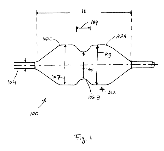
[0035] Fig. 1 illustrates a side view of a balloon catheter according to the
present
invention;
[0036] Fig. 2 illustrates the balloon catheter of Fig. 1 in a first state of
inflation according
to the present invention;
[0037] Fig. 3 illustrates the balloon catheter of Fig. 1 in a second state of
inflation;
[0038] Fig. 4 illustrates the balloon catheter of Fig. 1 in a third state of
inflation;
[0039] Fig. 5 illustrates an example pressure inflation curve of the balloon
catheter of
Fig. 1;
[0040] Fig. 6 illustrates an side view of a balloon catheter and diameter
sensing device
according to the present invention;
[0041] Fig. 7 illustrates an inflation device according to the present
invention;
[0042] Figs. 8-15 illustrate various techniques for providing balloon regions
with different
compliancy according to the present invention;
[0043] Fig. 16 illustrates a side view of a balloon having a plurality of
braided members
according to the present invention;
[0044] Figs. 17 and 18 illustrates a side view of a dual balloon catheter
according to the
present invention;
[0045] Fig. 19 illustrates a side view of dual balloon catheter according to
the present
invention;
[0046] Fig. 20 illustrates a side view of a dual balloon catheter according to
the present
invention;
[0047] Fig. 21 illustrates a side view of a multi-balloon catheter according
to the present
invention;
-13-
CA 02739326 2011-03-31
WO 2010/042869 PCT/US2009/060239
[0048] Fig. 22 illustrates a cross sectional view of the multi-balloon
catheter of Fig. 21;
[0049] Fig. 23 illustrates a side view of a multi-balloon catheter according
to the present
invention;
[0050] Fig. 24 illustrates a cross sectional view of the multi-balloon
catheter of Fig. 23;
[0051] Fig. 25 illustrates a side view of a multi-balloon catheter according
to the present
invention;
[0052] Fig. 26 illustrates a side view of a multi-balloon catheter according
to the present
invention;
[0053] Fig. 27 illustrates a cross sectional view of the multi-balloon
catheter of Fig. 26;
[0054] Fig. 28 illustrates a cross sectional view of a multi-chamber balloon
catheter
according to the present invention; and,
[0055] Fig. 29 illustrates a cross sectional view of a multi-chamber balloon
of Fig. 28 in a
molding chamber.
DETAILED DESCRIPTION OF EMBODIMENTS
[0056] Specific embodiments of the invention will now be described with
reference to the
accompanying drawings. This invention may, however, be embodied in many
different
forms and should not be construed as limited to the embodiments set forth
herein; rather,
these embodiments are provided so that this disclosure will be thorough and
complete, and
will fully convey the scope of the invention to those skilled in the art. The
terminology used
in the detailed description of the embodiments illustrated in the accompanying
drawings is
not intended to be limiting of the invention. In the drawings, like numbers
refer to like
elements.
[0057] Unless otherwise defined, all terms (including technical and scientific
terms) used
herein have the same meaning as commonly understood by one of ordinary skill
in the art
-14-
CA 02739326 2011-03-31
WO 2010/042869 PCT/US2009/060239
to which this invention belongs. It will be further understood that terms,
such as those
defined in commonly used dictionaries, should be interpreted as having a
meaning that is
consistent with their meaning in the context of the relevant art and will not
be interpreted in
an idealized or overly formal sense unless expressly so defined herein.
[0058] Figures 1-4 illustrate a preferred embodiment of an aortic
valvuloplasty catheter
100 with a non-compliant proximal region 102C, a non-compliant distal region
102A a semi-
compliant waist 102B according to the present invention. The semi-compliant
waist is
formed of a resilient elastomeric material that can return to its initial
shape after multiple
inflations. Generally, these regions 102A, 102B and 102C inflate to a dog bone
or
hourglass shape at certain inflation pressures to help achieve a desired
position of the
balloon 102 within the aortic valve 120. As described in greater detail below,
the semi-
compliant waist 102B can further expand against the annulus 118 of the valve
120, helping
the user determine the size of the annulus 118 and thus an appropriate
replacement valve
size.
[0059] The valvuloplasty balloon 102 is preferably disposed on a distal end of
a catheter
body 104, and delivered over a pigtail-end guidewire 106. At least one passage
within the
catheter body 104 is in communication with the balloon 102 to allow inflation
by liquid (or
optionally gas).
[0060] It should be understood that the present valvuloplasty catheter 100 can
be
created and used according to the techniques set forth in U.S. Patent
Publication No.
2005/0090846, the contents of which are incorporated by reference.
[0061] In operation, the valvuloplasty catheter 100 of the present invention
is introduced
through the femoral or brachial artery using a Seldinger technique to place a
vascular
sheath introducer in the peripheral vessel. Alternately, the valvuloplasty
balloon catheter of
the present invention can be placed transapically antegrade across the aortic
valve via a
surgical intercostal incision. For the transapical approach the distal bulb of
the dog-bone-
shaped balloon would be placed into the aortic sinus rather than the proximal
bulb as when
using the transfemoral approach. For the sake of simplicity, all further
dPsr:rintinn will hp
-15-
CA 02739326 2011-03-31
WO 2010/042869 PCT/US2009/060239
made with respect to the transfemoral approach. However, it should be
understood that a
variety of different placement procedures are possible according to the
present invention.
[0062] Returning to the transfemoral approach, a guidewire is placed across
the aortic
valve and the valvuloplasty balloon catheter 100 is advanced retrograde over
the guidewire
such that the pigtail 106 is positioned in the left ventricle. Next, using
fluoroscopy or other
imaging techniques, the balloon 102 is placed within the valve 120 so that the
distal portion
102A is positioned in the left ventricle outflow tract 114, the waist 102B is
positioned at the
annulus 118 and the proximal portion is positioned against the leaflets 116 in
the aortic
sinus 112.
[0063] As seen best in Figure 2, the balloon 102 is inflated to a pressure of
approximately 0.1 to 0.5 ATM (i.e., the pressure inside the balloon 102 is
slightly higher
than the pressure outside of it, about 0.2 ATM). At this pressure, the waist
102B is
prominently undersized relative to the proximal portion 102C and the distal
portion 102A as
well as the annulus 118. This undersized waist 102B helps "center" or position
the waist
102B at the annulus 118 and therefore achieve desired positions of all
portions of the
balloon 102. A slippery agent such as silicone oil or a hydrophilic coating
can be applied to
the exterior surface of the balloon to enhance this centered orientation.
Alternately the
outside surface of a portion of the balloon can be textured or roughened to
help hold the
balloon in position following inflation.
[0064] Next, the pressure in the balloon 102 is further increased; causing the
size of the
proximal portion 102C to increase as shown in Fig 3 and begin to push the
leaflets
outwards. This pressure can range between 0.5 and 5 ATM and preferably between
1-2
ATM. The size increase of the proximal portion 102C pushes the valve leaflets
116 open,
cracking the calcified portions and further creating hinge points.
[0065] The waist region 102B also increases in diameter at the previously
mentioned
pressure due to the compliant nature of the material in this area. The distal
portion 102A
may further increase somewhat in size, depending on variation in the
anatomical features
in the outflow tract. However, the expansion of the distal portion 102A is
i,itimatAly iimitArj
-16-
CA 02739326 2011-03-31
WO 2010/042869 PCT/US2009/060239
by the non-compliant material construction. Since the blood flow can only be
blocked for
a short period of time, the balloon 102 is quickly deflated after a short
period of time.
[0066] After the leaflets 116 have been "hinged" to an acceptable amount, the
user can
use the catheter 100 to estimate the size of the annulus 118 when subjected to
an internal
dilating load and therefore determine the appropriate size of the replacement
valve to
implant. The following methods are described to help determine the fully
stretched
diameter of the annulus 118.
[0067] Preferably, to determine the valve stretch diameter, the pressure
within the
balloon 102 is once again increased to expand the balloon 102 beyond that
shown in
Figure 3 to that of Figure 4. Contrast liquid is injected into the balloon 102
to allow it to
show up on imaging devices (e.g., fluoroscopy, x-rays, etc.). Since the waist
102B is
composed of a semi-compliant material, the further increased pressure causes
the waist
102B to extend outward. The proximal region 102C and distal region 102A remain
at
relatively the same diameter because these regions are constructed with a non-
compliant
material. As the pressure increases, the waist 102B extends radially outward
until it
contacts the annulus 118 as seen in Figure 4.
[0068] Once the waist 102B has reached the annulus 118, the valve 120 can be
imaged. This image illustrates the contrast liquid in the balloon 102 and
therefore the
shape of the waist 102B, which can be visualized and measured. Alternately,
radiopaque
markers may be embedded or otherwise located at the waist 1026 for
fluoroscopic imaging
purposes.
[0069] The user can help determine when the waist 102B has reached the annulus
118
by monitoring the change in pressure within the balloon 102 versus the change
in balloon
volume, or the change in pressure versus time if the volume rate of infusion
of fluid into the
balloon is maintained at a constant rate. A pressure manometer 122 or a
pressure
transducer can be connected in parallel with an inflation syringe at the
proximal end of the
catheter 100. Alternately a pressure transducer located in or near the balloon
or in fluid
communication with the balloon can also provide a pressure measurement ThA
nrPSSUrA
-17-
CA 02739326 2011-03-31
WO 2010/042869 PCT/US2009/060239
transducer can be a wireless transducer if desired. In this case an RF signal
can be sent
from the transducer to a receiver located outside the body of the patient to
indicate
pressure within the balloon.
[0070] Figure 5 illustrates an example graph that illustrates how pressure may
change in
an example balloon 102 over time as fluid volume is injected into the balloon
at a constant
rate or versus balloon volume. As the balloon 102 initially inflates, the
proximal region
102C and distal region 102A inflate and the waist inflates to its equilibrium,
low pressure,
state. Since these regions 102A and 102C are composed of non-compliant
materials, the
pressure within the balloon 102 remains relatively unchanged as the
unconstrained balloon
begins to fill with fluid (e.g., pressure slope 130 is relatively flat and at
a low pressure). As
the proximal region 102C and distal region 102A reach the limit of their non-
compliant
expansion, the pressure within the balloon begins to increase (e.g.,
relatively increasing
pressure slope 132) causing the waist 102B to expand beyond its equilibrium,
low
pressure, state. This pressure change during the expansion of the waist 102B
generally
follows a low upward slope 132 indicative of the compliance of the waist
material until the
waist 102B contacts the annulus 118, which significantly limits further
expansion of the
waist 102B. Therefore, the annulus 118 causes in an inflection point 133 in
the pressure
versus relative or absolute balloon volume curve followed by an increase in
the slope 134
that is indicative of the compliance of the annulus and the waist. The
absolute volume of
the balloon can be controlled by a constant volume pump and monitored to track
the
absolute volume injected into the balloon. Alternately, the constant volume
pump can be
used to control the relative volume of fluid injected into the balloon and the
relative volume
change can be plotted versus relative change in balloon pressure. If the fluid
is injected
into the balloon at a constant rate, then the slope 134 for the slope of Fig 4
can represent
the change in pressure versus time after contact is made for the waist with
the annulus.
[0071] The physician or operator has the capability with the present invention
of
providing a controlled valvuloplasty procedure with application of a
controlled force being
applied to the annulus. As the balloon waist comes into contact with annulus,
the inflection
point or change in slope of the pressure curve as shown in Fig. 5 is observed.
At this point
-18-
CA 02739326 2011-03-31
WO 2010/042869 PCT/US2009/060239
the pressure force within the waist is balanced by the constrictive force of
the waist and
very little force is being applied to the annulus. The physician or operator
can continue to
increase the pressure within the balloon and thereby apply only this
incremental pressure
above the inflection point pressure to the annulus. Since only this
incremental pressure is
being applied to the annulus, the annulus is protected against dissection that
can occur if it
were exposed to a large force. The slope of the pressure curve above the
inflection point is
also indicative of whether the annulus is a softer annulus or whether it is
hard and calcified.
Therefore the physician or operator is able to assess the effective modulus of
the annulus
by observing the slope of the pressure curve above the inflection point.
[0072] In this respect, when the user determines that the slope of the
pressure changes
from a slope similar to slope 132 to slope 134 (i.e., the inflection point
133), the waist 102B
has likely contacted the annulus 118. At that point, the user can image the
valve 120 as
previously described to determine the annulus diameter. Alternately, the user
or
manufacture may determine the size of the waist 1028 of balloon 102 at
different pressures
prior to a procedure. Therefore, the user can look at the pressure reading for
the inflection
point 133 to estimate the size of the waist 1028.
[0073] Preferably, a computer and computer software (e.g., specialized
pressure display
device or a PC) can be used to record and display the pressure in the form of
a graph. The
user can monitor the graph to manually determine the inflection point 133 and
therefore the
size of the annulus. Alternately, the computer software may monitor pressure
data (e.g.,
the slope) and automatically determine the inflection point 133 and convert
that pressure
value to a diameter size.
[0074] Figure 6 illustrates another preferred embodiment of an aortic
valvuloplasty
catheter 142 that is also capable of measuring the diameter of the annulus 118
of the valve.
Generally, the valvuloplasty catheter 142 is similar to catheter 100 shown in
Figures 1-4. A
sensor 144 can be located at or around the waist 102B of the balloon 102 to
measure the
expansion.
-19-
CA 02739326 2011-03-31
WO 2010/042869 PCT/US2009/060239
[0075] For example, the sensor 144 may include a resistive material formed
into a ring
around the waist region 102B or a portion of the waist region as shown in Fig
6. Upon
stretching of the waist 102B, the resistance of the material changes and can
be detected
using a circuit that monitors change in electrical resistance. In another
example, the sensor
144 may be a piezoelectric material located around a portion of the waist such
that an
electrical signal can be generated as the material is forced to stretch to
varying degrees.
[0076] Either of these previously mentioned sensors 144 are preferably
connected to an
electrical wire 146 located along the shaft 104 of the balloon to deliver the
signal from the
balloon 102 to the proximal end of the balloon catheter 140 and to an
inflation device that is
attached to the balloon catheter.
[0077] In another example, the sensor 144 may include either capacitive
coupled or
inductively coupled sensors that detect the proximity of one sensor to another
and are able
to identify changes in the separation between two such sensors. More
specifically,
components of the sensor may be located both at the balloon waist 102B and
within the
diameter of the waist 102B, on the shaft 104. Hence, as the waist 102B
expands, the
components of the sensors move apart from each other and can therefore be
measured.
[0078] In yet another example, ultrasound sensor 142 can be used to measure
the
diameter of the waist 102B as it contacts the annulus (e.g., as evidenced by
the inflection
point 133 in the slope of the pressure versus volume curve). Small ultrasound
sensors 142
are located in the interior of the balloon along the catheter shaft 104. Such
ultrasound
sensors are used in interventional balloon catheters and in other diagnostic
devices to
measure vessel diameter or the diameter of surrounding structures. The
diameter
measured by these sensors 142 during the inflection point 133 is then
indicative of the
diameter of the annulus 118. The ultrasound sensor 142 may also be capable of
identifying
the perimeter of the annulus and this information can be converted to an
annulus diameter.
[0079] In a preferred embodiment, the distal portion 102A achieves maximum
predetermined diameter at approximately 0.3-1 ATM. The proximal portion 102C
achieves
its maximum predetermined diameter after the pressure has caused the leaflAts
to hArnmA
-20-
CA 02739326 2011-03-31
WO 2010/042869 PCT/US2009/060239
displaced outwards at approximately 0.5- 2 ATM. Preferably, the catheter 100
(or catheter
140) is configured to not exceed approximately 3-5 ATM of pressure so as to
remain safely
contained by known dilatation balloon materials.
[0080] A desired pressure limit (e.g., 3-5 ATM) within the balloon 102 can be
achieved
with the inflation device 150 shown in Figure 7 (described elsewhere in this
specification).
For example, a cutoff safety or pressure spill-off valve contained in a
balloon inflation
device can be activated at a desired maximum pressure.
[0081] In one balloon embodiment, the waist 102B assumes an oval shape when
inflated to better engage the generally non-circular valve cross section of
the annulus 118.
The waist 102B can cause the annulus to become round as it comes into contact
with it or
applies an outward force against the annulus as the annulus becomes rounded.
The force
applied by the waist outward onto the annulus is, however, less than the
internal pressure
of the balloon since the semi-compliant waist 1028 is providing an inward
constrictive force
that acts to balance the outward acting internal pressure. The entire internal
balloon
pressure also acts to cause the leaflets to be pushed outward into the sinus
region.
[0082] Preferably, the proximal region 102C has an inflation diameter that is
sized
similarly but slightly smaller than the aortic sinus 112 that is located
adjacent to the
ascending aorta 110. This diameter size of the proximal bulbous region 102C
provides
greater distension to the leaflets 116 and thereby more effectively crack the
calcium
deposits than could be attained with a standard cylindrically shaped balloon.
[0083] Alternately, the balloon 102 can be constructed such that when a
specified
volume of fluid is place within its interior, the waist diameter is directly
known. Thus by
controlling and knowing the volume of inflation fluid that is delivered into
the balloon along
with monitoring the pressure within the balloon, the waist diameter can be
determined (by
knowing the volume) when the waist comes into contact with the annulus (by
monitoring the
pressure and noting the inflection point). A positive displacement fluid
delivery device such
as a syringe can be used to assess the volume of fluid delivered to the
balloon. A pressure
graph similar to Figure 5 can be created for monitoring purposes in which thA
v-axis anain
-21-
CA 02739326 2011-03-31
WO 2010/042869 PCT/US2009/060239
represents the balloon pressure but the x-axis represents the absolute volume
delivered to
the balloon rather than a relative volume delivered when the inflation fluid
is delivered at a
constant rate.
[0084] Figure 7 illustrates an inflation tool 150 according to the present
invention used to
deliver contrast fluid to the valvuloplasty balloon 100. Compression of a
handle 152 drives
a plunger 160 down a barrel 152 to force the contrast fluid into the
valvuloplasty catheter
171. As the lowered plunger 160 near the stops 166, contrast fluid is driven
in a two stage
process.
[0085] In the first stage, contrast fluid travels at a rapid rate out of the
outflow port 182 to
fill the balloon 100 with approximately 90% of its balloon volume in
approximately 1-5
seconds. In the second stage, the top plunger then drives the remaining about
1-2 cc of
fluid through the side holes 178 located in the lower plunger at a controlled
rate that is
limited by fluid resistance through the holes 178.
[0086] To remove the fluid from the balloon 100, a toggle switch 158 is
activated to
allow a compression of the handle 152 to force the plunger upward instead of
downward,
creating a vacuum that causes the contrast fluid to be removed rapidly through
the one way
valve 168 located in the lower plunger 180. The lower plunger 180 rides upward
from the
vacuum force until it comes into contact with the stops 166 and is ready for
the next deliver
of fluid to the balloon.
[0087] A variable resistor 156 serves as a fluid volume measure to track the
relative
amount of fluid delivery (or change in volume delivered) to the balloon 100.
Other digital
position sensors can also be used to detect the relative movement of the
plunger with
respect to the barrel of the delivery device. The sensor that detects fluid
volume change in
the barrel sends an electrical signal to the display 164 located on the
inflation device, the
balloon catheter, or on a separate member located outside of the patients
body.
[0088] A balloon pressure transducer 184 is located in the balloon 100 near
the junction
with the catheter shaft 104. A barrel pressure transducer 172 is also located
in the delivery
-22-
CA 02739326 2011-03-31
WO 2010/042869 PCT/US2009/060239
device or in the barrel 162 of the inflation tool in order to account for
balloon pressure
variability due to inertia and shaft compliance. Only one of the pressure
transducers may
be needed to ensure that the pressure reading is an accurate measure of the
balloon
pressure. The pressure reading representative of the balloon pressure and the
relative
balloon volume are detected by a readout display 164. The readout display
comprises a
computer chip along with the electronic circuitry to receive the pressure and
relative balloon
volume signals, store them, and plot pressure versus relative or absolute
balloon volume.
The computer chip also computes the slope of the pressure versus volume curve
and is
able to detect a change in this slope.
[0089] When the slope of the pressure versus volume curve reaches an
inflection point
or a change in slope, this detected pressure will be captured by the computer
chip and
displayed along with the diameter of the balloon at this pressure. The
diameter of the
balloon will be calculated by the computer chip and is reflective of the
modulus of the waist
region and the pressure at the inflection point. This waist diameter will then
indicate the
annulus diameter which will be displayed by the readout display.
[0090] It is further noted that the inflation device can also be operated such
that fluid is
delivered to the balloon catheter at approximately a constant rate. In this
case the
computer chip found in the readout display would be receiving pressure data
and storing it
versus time elapsed since the start of fluid injection into the balloon. The
computer chip
would in this instance plot pressure versus time and would compute the slope
of this curve
and detect a change in this slope. When the slope of the pressure versus time
curve
reaches an inflection point, the pressure at this point is captured by the
computer chip and
is converted to a waist diameter reading that is displayed by the readout
display.
[0091] Preferably, the balloon 102 comprises a single internal compartment.
However,
multiple compartments with their own inflation lumens are also possible. For
example, the
balloon 102 may include a proximal compartment, a middle waist compartment and
a distal
compartment, each allowing for individual inflation control.
-23-
CA 02739326 2011-03-31
WO 2010/042869 PCT/US2009/060239
[0092] The balloon 102 can be made from a variety of different materials known
in the
art for use in balloon catheters. For example, compliant or semi-compliant
material can be
selected from nylon, Surlyn, vinyl, PVC, polyethylene, polyurethane, Pebax,
olefins or
copolymers of these materials. In another example, non-compliant material can
be
selected from PET (Dacron), Teflon, polyimide, Kevlar wraps, metal, polymer or
fibrous
material. In a further example, compliant or semi-compliant material can be
made to be
relatively non-compliant by applying crosslinking such as ebeam, chemical or
other
crosslinking treatments. In yet another example, a non-compliant material can
be made
more compliant or semi-compliant by treating it with ebeam, chemical treatment
or other
process to weaken the molecular structure of the balloon material.
[0093] In one embodiment, the outside of the balloon 102 can be coated with a
desired
drug for elution during a procedure. For example, olimus or paclitaxel type
drugs could be
used or other types of drugs to offset the local deposit of calcium and
possibly alter
osteoblast calcium deposition.
[0094] As previously described, the balloon embodiments of the present
invention may
have regions of different compliance (e.g., non-compliant, semi-compliant and
compliant).
Some example techniques for creating balloons with these characteristics are
described in
greater detail below.
[0095] In one example shown in Figure 8, a balloon 200 can be created by
extruding a
first tube 206 of semi-compliant material and a second tube of non-compliant
material 204.
One or more segments of the non-compliant tubing 204 can be placed over the
semi-
compliant tubing 206 concentrically in the region or regions that are to be
non-compliant
(e.g., proximal section 102C and distal section 102A). This tubing assembly is
then placed
into a heated mold 202 that forms the external shape of the balloon 200 while
pressure,
internal to the tube assembly, is also applied to maintain desired contact
with the mold
contours. An adhesive agent or thin polymer layer can also be applied between
the
concentric tubes 204 and 206 (preferably prior to the mold process) to enhance
bonding to
each other.
-24-
CA 02739326 2011-03-31
WO 2010/042869 PCT/US2009/060239
[0096] Additionally, axially oriented fibers can be adhered or embedded across
the waist
region to help reduce axial length increase in the waist as the balloon 200 is
exposed to
increasing pressures. The axial strands can be individual polymeric or
metallic strands or
multifilament strands that are bonded to the outside of the waist region.
Alternately, the
strands can be sandwiched between two layers of balloon material.
[0097] In another example seen in Figure 9, a balloon 208 can be created by
coextruding two tubes having an inner tube 206 with semi-compliant material
and an outer
tube 204 having non-compliant material. A portion of the outer, non-compliant
tube 204
can be etched away in a region desired to be semi-compliant (e.g., the waist
102B).
Preferably, laser etching, plasma etching, mechanical etching or chemical
etching are
used. The non-compliant tube 204 can be partially etched through or fully
etched through,
leaving the semi-compliant tube exposed 206. Next, the coextruded tubes are
placed in a
heated mold where pressure internal to the tube presses the tube against the
mold
contours to form the desired mold shape. Alternately, the coextruded tubes can
be molded
prior to etching of the non-compliant material 204. After molding, the outer
tube can be
further etched in locations to more precisely achieve a desired compliance (or
non-
compliance).
[0098] In another example construction method, a non-compliant outer layer can
be
applied over the outside of the entire semi-compliant balloon and axial slits
located in the
waist region can be formed in the outer non-compliant layer in the waist to
allow the semi-
compliant waist to enlarge in diameter when exposed to increasing internal
pressure.
[0099] In yet another seen in Figure 10, a balloon 212 can be created by
molding a
semi-compliant material 206 into a desired balloon shape. The areas desired to
be semi-
compliant can be masked or covered with a mask 214 and a thin non-compliant
polymer
layer 216 can be applied onto the unmasked regions (e.g., the distal region
102A and
proximal region 102C of balloon 102). Such noncompliant materials can include
polyimide,
polyethylene terephthalate, fiber reinforced polymers, and many polymers
commonly used
for noncompliant balloons. Preferably, the non-compliant polymer 216 can be
applied by
-25-
CA 02739326 2011-03-31
WO 2010/042869 PCT/US2009/060239
spray or dip coating and can be further treated to provide crosslinking to
enhance the non-
compliant properties. Regions of the balloon can be masked during various
stages of the
process to provide various levels or areas of compliance and noncompliance.
[00100] In yet another example seen in Figure 11, a balloon 218 can be created
by
molding a non-compliant material 204 into a desired balloon shape. Next, the
non-
compliant material 204 can be post processed in desired areas (e.g., the area
that would
become the waist 102B of balloon 102 in Figures 1-4) to achieve semi-compliant
characteristics. This post processing may include ebeam, chemical treatment or
mechanical treatment. In a more specific example, ebeam will reduce
crosslinking in most
fluoropolymer materials and therefore may increase the compliance in the
treated area.
[00101] In another example shown Figure 12, the balloon 222 can be created by
molding
a semi-compliant material 206 into a desired balloon shape. Next, the semi-
compliant
material 206 can be post processed in desired areas to achieve non-compliant
characteristics. This post processing can include, for example, ebeam to cause
crosslinking between most hydrocarbon backbones such as those found in
polyethylene.
Again, a mask 214 can be used to prevent treatment of areas desired to be semi-
compliant.
[00102] In yet another example seen in Figure 13, a balloon 226 can be created
by
molding non-compliant material 204 in a desired balloon shape and placing
elastic
members 228 around the region that is desired to be semi-compliant shown in
Fig 6. The
elastic wrap preferably has a native diameter (i.e., a mostly or partially
unstretched
diameter) that is smaller than the native diameter of the non-compliant
balloon shape. The
non-compliant material 204 adjacent and near the elastic wrap 204 may be
forced to fold,
bend or wrinkle to allow for semi-compliant expansion during use.
[00103] In yet another example, a balloon can be created by molding a material
with a
plurality of circumferential fibers embedded or otherwise located along the
axial length of
the balloon. By increasing or decreasing the spacing of these fibers, the
compliance can
be increased or decreased respectively. Additionally, the fibers can be
increase or
decreased in diameter to further modify the compliance characteristics of the
haIInnn_
-26-
CA 02739326 2011-03-31
WO 2010/042869 PCT/US2009/060239
[00104] In another example seen in Figure 14, a balloon 230 can be created by
a semi-
compliant material 206 that is molded to a balloon shape. A non-compliant
material 204 is
separately molded to the balloon shape. The distal and proximal portions are
cut off of the
non-compliant material 204 and placed over the distal and proximal ends
respectively of
the semi-compliant balloon material 206. Pressure and temperature is applied
to the
balloon 230 in a mold to fuse the layers together or adhesive or polymer can
also be
applied between the layers to enhance bonding.
[00105] In another example seen in Figure 15, a balloon 232 can be created by
a molding
a semi-compliant material 206 and separately molding a non-compliant material
204 into a
balloon shape. The middle waist portion of the non-compliant material 204 is
weakened to
create a more compliant region 234. The non-compliant material 204 is placed
over the
semi-compliant material 206 and the balloon 232 is placed back in the mold
with pressure
and heat to fuse the materials 204 and 206 together as previously described.
Adhesive or
similar bonding material may also or alternately be used between the materials
204 and
206.
[00106] In another embodiment shown in Figure 16, a balloon 326 is formed with
braided
members 238 that extends at least through the semi-compliant waist region
236B. The
braid can be constructed from multifilament strands of polyethylene
terephthalate,
polyethylene, or other polymer or thin metal stands. The braid can be bonded
to the
balloon using UV curable acrylic, polyurethane, or other bonding agent. The
braid will allow
the waist 236B to enlarge in diameter while causing the waist 236B to reduce
in length.
This balance will allow the inflection point 133 in the delta pressure / delta
volume curve to
become more pronounced as contact is made by the waist 236B with the annulus
118. The
braided members 238 can also ensure that the waist 236B does not over extend
in
diameter and cause dissection to the annulus 118. The braided members 238 can
also
help to hold the non-compliant regions 236A and 236B such that they do not
expand in
diameter and thereby help to improve the observation of the inflection point
133. The braid
angle of the braided members 238 in the waist region 236B may, for example, be
more
axially oriented than that in the bulbous end regions 236A and 236C of the
balloon 236.
-27-
CA 02739326 2011-03-31
WO 2010/042869 PCT/US2009/060239
[00107] Optionally, a third fiber having substantially a circumferential
direction and having
a diameter approximately equal to an upper limit diameter can be braided into
a standard
braid that has a fiber angle with respect to the axis of about 42-75 degrees.
The presence
of the third fiber may limit diameter of the braid such that it cannot extend
beyond the upper
diameter limit set by the circumferential strand.
[00108] In another embodiment, braided member can be bonded over the balloon
in its
configuration that is not yet expanded. Preferably, this bonding occurs when
the waist is
expanded to approximately an 18 mm diameter. Here the braid is forced into a
smaller
diameter by pulling apart on each end of the braid. This smaller diameter
portion is then
bonded to the waist. Further, the braid is bonded to the larger diameter non-
compliant end
portions of the balloon.
[00109] An alternate method for forming one embodiment of the balloon includes
forming
a zig-zag shape from a multifilament strand of PET, Dacron, nylon, or other
high strength
material ranging in diameter from 0.0005-0.003 inch and preferably 0.001-0.002
inch. Each
micro fiber of the multifilament strand can be approx. 5-20 microns in
diameter. Also nitinol
multifilament or monofilament strands of similar dimensions can be used. The
zig-zag
shape can have an angle from the average axis direction of 30-60 degrees and
preferably
40-50 degrees for a diameter change for the waist of 18 to 24 mm as the zig-
zag strand
becomes straightened under force. The zig-zag strands are formed by placing
the generally
straight strand along a comb-like fixture that forces the strand between the
opening of
another the combs-like fixture. Similarly the teeth of a cross cut wood saw
can be used as
a mold to force the strands into the valleys of another cross cut saw. The
strand is then
heat treated to form a zig-zag pattern while being held by the fixture or
mold.
[00110] With the balloon in a smaller diameter configuration, the zig-zag
strand is wound
around the waist region (preferably inflated to about 18 mm in diameter) in a
spiral manner.
Note that circles of zig-zag material can also be used. For example a zig-zag
can be cut
from a tube or nitinol using a laser and placed around the waist of the
balloon. The zig-zag
-28-
CA 02739326 2011-03-31
WO 2010/042869 PCT/US2009/060239
strands are then bonded to the waist using an elastomeric adhesive such as
silicone,
polyurethane, a copolymer of these polymers, and other polymers.
[00111] In another embodiment, a dog-bone shaped balloon can be formed by an
approximately 25 mm in diameter cylindrical balloon composed of a non-
compliant material
such as PET or nylon. In the central region of this balloon where the waist is
intended to be
located, the non-compliant material is folded. This can be done by the initial
mold that forms
the balloon to begin with such that it has a rippled or corrugated shape
running axially in the
waist region. Alternately, it can be formed as a post process by placing a
metal element
inside the balloon from each end opening and a mold outside the balloon and
allowing the
balloon material to be forced into a rippled or corrugated shape. The
corrugated shape will
allow the non-compliant balloon to fold in a controlled manner when it is
expected to constrict
down due to the elastomeric waist material (previously described).
[00112] As a second step, an elastomeric waist can be formed that extends from
a small
diameter of about 18 mm in the center of the waist to a diameter of approx 24
mm at the
ends of the waist. This component can be formed from a molding operation or an
extrusion
operation followed by a post processing method to form or mold the proper
shape. The
material can be silicone, polyurethane, a copolymer, or other elastomeric
polymer.
[00113] The non-compliant balloon is then expanded out to its expanded
configuration at
a lower pressure ranging from 0.1-4 Atm. The waist is then placed over the
center of the
non-compliant balloon and bonded to the center. Upon release of pressure, the
waist
portion of the balloon contracts due to the shape and force of the waist
portion. Upon
expansion to a larger pressure, the non-compliant balloon material located in
the waist
region ensures that the waist cannot expand beyond 25 mm.
[00114] As previously described, the waist 102B of the balloon 102 (Figs. 1-4)
is
preferably compliant or semi-compliant, meaning its diameter will differ
between the
proximal portion 102C and distal portion 102A, depending on the inflation
pressure within
the balloon 102. In other words, the non-compliant regions will remain
relatively constant in
diameter during inflation while the semi-compliant regions will grow with mnrP
nrP.SSI1rP.
-29-
CA 02739326 2011-03-31
WO 2010/042869 PCT/US2009/060239
For example, the waist 102B may be 16-20 mm in diameter in its equilibrium
state and
capable of stretching to engage the annulus at 19-25 mm in diameter whereas
the proximal
and distal ends remain at a relatively fixed diameter ranging for
approximately 23-28 mm.
[00115] Preferably, the waist 102B of the balloon 102 is "undersized" in its
equilibrium,
low pressure, state (i.e., sized smaller relative to the annulus) by about 3-5
mm. For
example, if the target annulus 118 of the patient's valve 120 is about 23 mm,
a balloon 102
with a waist 102B at equilibrium is about 20 mm. Preferably, this example
waist 102B
grows by 2 mm at a pressure of 2 ATM to a diameter of 22 mm. At this diameter
of 22 mm
and an internal pressure of 2 ATM, the outward force exerted upon the annulus
is about
zero since it takes 2 ATM of pressure just to reach 22 mm in diameter. As this
example
balloon 102 becomes further pressurized to 3 ATM, its waist 102B grows further
to 23mm
and it may come into contact with the wall of the annulus 118, but would
likely not exert
much, if any pressure on the annulus 118 (since the waist 102B would just
begin to engage
in contact).
[00116] In contrast, the proximal portion 102C and distal portion 102A apply
an outward
force of about 3 ATM against the leaflets 116 and left ventricle outflow tract
114 since these
portions 102A and 102C are non-compliant and are in contact with these
structures starting
at the equilibrium pressure. If the pressure was further increased to 4 ATM,
only 1 ATM of
outward force maximum would be applied to the annulus 118. In this example, it
is
believed that exposure of the annulus 118 to a pressure of 2 ATM, for example,
or less will
not result in a dissection (i.e., damage). If the actual annulus diameter was
22 mm and the
waist came in to contact with the annulus at 2 atm, the annulus could be
exposed to 2 ATM
of pressure if the internal balloon pressure was 4 ATM.
[00117] Further, the waist 102B preferably self-locates such that the waist
118
automatically locates over the annulus 118, thereby avoiding damage to other
portions of
the valve 120. For example, if the waist 102B of the balloon was located low
into the left
ventricle outflow tract 114, then the proximal portion 102C, normally located
in the sinus
112, may expand in the annulus 114 and possibly cause dissection. If the waist
102B was
-30-
CA 02739326 2011-03-31
WO 2010/042869 PCT/US2009/060239
somehow positioned in the sinus 112, then the inflated waist 102 would not
achieve a
diameter capable of "cracking" the calcified leaflets 116 at their base. The
length of the
waist 1028 must be adequately sized to the annulus 118 to avoid similar
outcomes.
[00118] To aide in the self positioning, the outside of the balloon 102 can be
slippery so
as to enhance its ability to "slide" into a desired position with the waist
102 positioned over
the annulus 118. Alternately, the outer surface of the balloon can be textured
or roughened
to help hold the balloon into position during the inflation.
[00119] Note that the term non-compliant, which has been used in this
specification,
refers to material that is relatively inelastic. In other words, such material
has little or no
stretch under most, intended circumstances, such as application of moderate
pressure.
The terms compliant or semi-compliant, which have been used in this
specification, refer to
material that includes at least some elasticity. In other words, such material
will stretch with
little or no damage to the material under most, intended circumstances, such
as application
of moderate pressure. The waist material should preferably also be resilient
such that it
returns to its initial diameter when the pressure is reduced.
[00120] The specific balloon description presented below is an example of one
balloon
size that is intended to cover a size range of annulus diameters from 21 to 24
mm. It is a
dog-bone shaped balloon with a waist that is semi-compliant and non-compliant
bulbous
end-regions. For the purposes of this specific example, Figure 1 will be
further referred to.
[00121] The balloon 102 has a length 111 of between about 40-80 mm and
preferably 50-
70 mm. Regions 102A and 102C are non-compliant while region 102B is semi-
compliant.
The balloon 102 has a working pressure of between about 4-5 atm; a burst
pressure
between about 6-7 atm with the tear direction preferably in the axial
direction. The wrap
profile of the balloon 102 is about 10-12Fr and the catheter shaft 104 is
preferably between
about 9-12Fr. The guidewire lumen is configured for over the wire techniques
with about a
.036" wire. The balloon waist 102B has a length 109 when of about 5-10 mm
axial length
at 0.1 ATM and about an 18-21 mm maximum diameter 105 in its center.
Preferably, each
-31 -
CA 02739326 2011-03-31
WO 2010/042869 PCT/US2009/060239
section 102C and 102A have a maximum diameter 103 and 107 of between about 25-
56
mm.
[00122] The following are example measurements of the balloon waist 102B at
various
pressures:
Balloon Pressure Diameter
0-0.1 ATM 18
1 ATM 19.5
2 ATM 21
3 ATM 22.5
4 ATM 24
[00123] Preferably, two circumferential Angiographic marker bands are located
on the
surface of the balloon 102 and optionally on the central shaft 104, within the
balloon and
near the waist area 102B. Such marker bands can be a ring of radioopaque
material
swaged or bonded onto the catheter shaft or applied via vapor deposition or
coating
process onto the outside of the balloon
[00124] Balloon ends can be formed at 4 mm OD at each end. One example places
approximately a 0.038 in ID x 0.046 in OD tubing through the catheter shaft
and through
the balloon to provide passage for a 0.035 inch guidewire. The distal end of
the balloon is
bonded to the guidewire tubing. Some expansion in the length of the balloon
may occur
under pressure due to expansion of the waist. It may be desirable to reduce
any balloon
curving that occurs as the balloon is expanded under pressure by preferably
using a
guidewire tubing with similar axial expansion as the balloon.
[00125] In the previous example, the waist is suggested to undergo an
expansion from
about 18 mm to 24 mm as the pressure increases from a small pressure above
zero ATM
(i.e., 0.1 ATM) to 4 ATM. This waist compliance is described as a linear
compliance.
-32-
CA 02739326 2011-03-31
WO 2010/042869 PCT/US2009/060239
However, since most elastomeric polymers are not linear, it is desirable that
the middle of
the waist achieves the diameters indicated in the example at the two points
which occur at
2 ATM and 4 ATM. These two middle waist diameters are 21 mm and 24 mm at 2 ATM
and 4 ATM, respectively. Preferably, the diameter of the middle of the waist
is smaller than
18 mm in its natural state (i.e., at approx zero pressure) in order achieve
the 21 mm and 24
mm data points.
[00126] In some examples, the semi-compliant waist is joined to non-compliant
bulbous
ends. This junction of a semi-compliant material with a non-compliant material
can
generate a discontinuity that may result in breakage. A small transition
region may reduce
this breakage although it should be noted that such a transition may not be
appropriate for
all balloon materials and designs. If a transition region is necessary, then
the transition
region can be formed in the waist, thereby making the axial length of the
waist somewhat
smaller than the 5 mm -10 axial length listed on the drawing.
[00127] The non-compliant bulbous regions 102C and 102A are intended to
maintain a
fixed diameter from 1 ATM to 4 ATM. If the non-compliant regions stretch with
an increase
in pressure, it may be difficult to detect the stretching waist by monitoring
the balloon
pressure. Therefore the bulbous regions should preferably be made of a
material that
resists any circumferential stretching.
[00128] As discussed in U.S. Publication No. 2005/0090846, the contents of
which have
been previously incorporated by reference in this application, an alternate
embodiment of a
balloon is possible according to the present invention, including a non-
compliant waist and
semi-compliant proximal and distal portions. In one example, the balloon can
have the
characteristics described below, although it is recognized that this balloon
embodiment may
not have the ability to measure the annulus in a manner described for the semi-
compliant
waist balloon of Figures 1-4.
[00129] The balloon includes a waist that is non-compliant and at least one
end portion
that is semi-compliant. However, both end regions may also be semi-compliant.
The end
portions are able to expand under pressure thereby allowing the bulbous
nrnximnl nnrtinn
-33-
CA 02739326 2011-03-31
WO 2010/042869 PCT/US2009/060239
to push the leaflets back to an amount that is dependent upon the internal
balloon
pressure, while the waist cannot over-distend the annulus.
[00130] An internal pressure of approx 2 atm can cause the proximal portion of
the
balloon to expand outwards by approximately 10-20 % beyond its equilibrium
size causing
the diameter of the balloon to extend from approx 20 mm to 24 mm. The balloon
can be
constructed such that the balloon shape is bulbous in a manner described
earlier where the
waist is smaller than the bulbous regions by approximately 15-25 %.
Alternately, the
balloon can be almost cylindrical in shape with the waist only approximately
10% smaller
than the bulbous ends at a pressure of 1.5 atm. The waist can range in length
from 1-10
mm.
[00131] The balloon can be constructed by applying a non-compliant material, a
spiral
wrap, a braid, or woven fabric in the waist region of a semi-compliant balloon
to make the
waist into a non-compliant region. Balloon strengthening can alternately be
applied to the
waist via chemical or other means of crosslinking.
[00132] In anther alternate embodiment, the entire balloon may be composed of
non-
compliant material. A dog-bone shaped balloon with a non-compliant waist
approach may
require a close estimate of the annular diameter within 1 mm and therefore the
balloon
waist should be sized to match this diameter. In one example, a dog-bone
shaped balloon
is created such that it is entirely non-compliant and provides the balloon
sizes in increments
of 1 mm annular diameter size variations.
[00133] This all non-compliant balloon operates at a pressure ranging from 3
atm to very
high pressures of over 10 atm. Safety is obtained by ensuring that the waist
does not grow.
Preferably, the dog-bone shaped balloon is slippery so that it moves to self-
center the waist
at the annulus 118. Failure to self center may result in the larger portions
of the balloon
being positioned at the annulus and thereby causing the annulus to dissect.
[00134] In another embodiment, a dog-bone shaped balloon is entirely semi-
compliant.
Hence, this balloon configuration does not constrict the growth of the bulbous
end regions
-34-
CA 02739326 2011-03-31
WO 2010/042869 PCT/US2009/060239
of the balloon. The change in the pressure/ volume curve that is observed when
the waist
comes into contact with the annulus is not as obvious as with other described
embodiments
since the end bulbous regions are still able to grow in volume as the pressure
inside the
balloon is increased.
[00135] One difference from the previously described, all non-compliant
balloon is that a
compliance curve may be used to size the diameter of the annulus. Following
contact of
the waist with the annulus, the annulus could increase in diameter due to an
increased
operating pressure but the waist would be sized accordingly such that annular
expansion
would not be significant. The sinus and distal portion of the balloon would
continue to
increase proportionally with increasing pressure. The diameter that is
selected for the
balloon waist would be set by a diameter that would not stress the annulus. If
the material
for this semi-compliant balloon were such that generally higher pressures were
being used
during the inflation and prior to contact of the waist with the annulus (i.e.,
greater than 2-5
atm), then the entire balloon could be made of the same semi-compliant
structure. The
internal pressure within the balloon would impart very little force to the
annulus. The safety
is gained by ensuring that the annular diameter is larger than the waist
during leaflet
expansion and inflation is terminated soon after contact of the waist with the
annulus.
Some operating challenges with the totally semi-compliant balloon can occur
due to
continued expansion of the bulbous portions of the balloon after that waist
makes contact
with the annulus, thereby reducing the magnitude of the slope change in the
pressure
versus volume curve after the inflection point.
[00136] In a manner similar to the previously described, all non-compliant
balloon, the
balloon may be slippery to ensure that it self centered on the annulus. If it
did not self
center, one could easily cause an annular dissection due to placement of the
proximal or
distal portions of the balloon in the annulus region. This higher pressure
semi-compliant
balloon may be manufactured out of nylon or other semi-compliant material or
it may use a
composite wall structure having a braid or other fiber matrix bonded to or
contained within
the balloon wall, if the profile was not a limiting factor.
-35-
CA 02739326 2011-03-31
WO 2010/042869 PCT/US2009/060239
[00137] Figures 17 and 18 illustrate another embodiment of a valvuloplasty
balloon 242
according to the present invention. This balloon 242 includes a larger
diameter region
242B for expanding against valve leaflets and a smaller diameter region 242A
for anchoring
in the left ventricle outflow tract. The size of the patient's annulus can be
measured by a
smaller inner balloon 248 that is located over an inflation port 248 on the
catheter shaft 244
and located within the balloon 242.
[00138] The inner balloon 248 has an inner balloon inflation lumen that
connects to port
246, allowing the inner balloon 248 to be inflated first and serve as a
positioning balloon
that locates this balloon upstream and adjacent to the aortic annulus. The
inner balloon
can be bonded to the shaft to obtain a shape or profile that best allows
positioning of the
balloon. Once this balloon is in place, the larger outer balloon can be
inflated using a
separate outer balloon inflation lumen to dilate the leaflets via the sinus
portion of the outer
balloon 242.
[00139] This sinus portion 242B of the outer balloon has a larger diameter
than the
locator balloon 248 and is sized to push the aortic leaflets outward into the
aortic sinus.
The outer balloon can have a distal shape that is cylindrical as seen in
Figures 17 and 18, a
balloon 250 with proximal end 250B and a distal end 250A that follows the
inner balloon
248, or a balloon 252 having a bulbous proximal end 252B and a bulbous distal
LVOT
portion 252A that forms a waist region 252C as seen in Figure 20.
[00140] The outer balloon of the embodiments of Figures 17-20 can be
constructed using
any of the construction means described in the previous embodiments including
non-
compliant, semi-compliant or a combination of both materials. The outer
balloon can, for
example, have a semi-compliant waist and be used to measure the annular
diameter as
described earlier.
[00141] The inner balloon can be constructed of either semi-compliant or non-
compliant
materials. The inner balloon can also be used to assess the diameter of the
annulus by
monitoring its volume and calculating the diameter of the annulus as
previously described
in this specification. Pressure measurements made in either the inner balInnn
nr hAtween
-36-
CA 02739326 2011-03-31
WO 2010/042869 PCT/US2009/060239
the inner and outer balloon can also be used as described earlier to monitor
change in
pressure versus change in volume to identify that contact has been made with
the annulus.
Various sensors such as ultrasound, piezoelectric, electrical resistance and
others can be
used along with this embodiment as described in previous embodiments to
measure the
annulus diameter.
[00142] It should be understood that drugs may be applied the outside of any
of the
previously described embodiments for treatment purposes. For example, drugs
similar to
the "olimus" or "paclitaxel" groups may be used to offset the local deposit of
calcium and
possibly alter osteoblast calcium deposition.
[00143] It is also possible to configure the shape of the balloon 102 to allow
perfusion
during the procedure. For example, perfusion channels or passages may be
included in
the balloon 102.
[00144] Figures 21 and 22 illustrate a perfusion balloon device 260 that
includes 5
individual balloons 262A-E or 5 balloon compartments arranged in a pentagon
shape
around a flow area 266. Each of the balloons 262A-E are attached to each other
at
attachment sites 264. Each balloon 262 provides support to the central flow
area 266 by
intimate contact with two other balloons 262. The central flow area 266 for
the 5 balloons
262 is preferably about 0.48 cm sq, which is though to be enough to maintain
adequate
perfusion to the brain while the balloons 262 are inflated. Fewer balloons can
also be used
however this results in a smaller central flow area. If 3 balloons are used,
the area is
preferably about 0.056 cm sq and for four balloons it is preferably about
0.237 cm sq. The
shape is more stable with fewer balloons however the flow area is much less.
If more than
balloons 262 are used, the flow area may be increased, however the stability
of the
shape may be reduced.
[00145] Each balloon 262 is attached to a central manifold 268 at the proximal
end of the
balloons 262 such that all of the balloons 262 are inflated simultaneously.
The flow of
blood is provided via access between the balloons 262 at the distal end and
flows down the
central flow area 266 and passes between the balloons 262 at the proximal Pnd-
it is nntAdl
-37-
CA 02739326 2011-03-31
WO 2010/042869 PCT/US2009/060239
that the 5 balloons 262 can be formed such that the balloon inlets are located
off to one
side of the assembly rather than located on the central axis of the assembly
as shown.
Locating the inflation inlet and manifold off of the central axis would
potentially allow for a
more direct flow path for the blood into and out of the assembly.
[00146] Figures 23 and 24 illustrate a balloon valvuloplasty device 270 which
is similar to
the previously described device 260 except for the addition of an external
wrap 272 around
the outside of the 5 balloons 262. The external wrap 277 is a thin but strong
plastic
material that also serves as a balloon around the outside of the five balloons
272. The
external wrap 272 can also be preferably attached to the 5 balloons 262 at
attachment sites
276. Flow of fluid such as blood can occur through the central region 273
located between
the five balloons 262.
[00147] The attachment of the balloons 262 to the external wrap 272 not only
provides
stability to the shape of this balloon assembly 270 but also allows inflation
to occur between
each of the balloons on the outside of the balloons in external spaces labeled
274 via a
separate inlet lumen 275 to the external space. Expansion of the external
space 274 at an
external wrap pressure allows the entire structure to provide expansion to
external tissue
forming a round or continuous shape. It is believed that the external wrap
pressure should
be somewhat lower than the balloon inflation pressure such that the balloons
are providing
an even support to this external wrap. The pressure in the external wrap
preferably ranges
between 1 and 6 ATM and preferably between 2 and 5 ATM. The pressure in the 5
balloons may range from 2 to 20 ATM.
[00148] A seal must be made between the external wrap and each of the
individual
balloons 262 separating it from the flow area 266 for the perfused blood
through the central
flow area 266 of the balloon assembly 270. This flow passage must be provided
at the
proximal and distal end of the balloon assembly 270 and includes an attachment
with each
of the 5 balloons 262. A continuous passage for blood is formed from the
central flow area
266 through a space located between at least two balloons that are themselves
sealed
independently to the outer wrap in the proximal and distal ends of the balloon
assembly.
-38-
CA 02739326 2011-03-31
WO 2010/042869 PCT/US2009/060239
[00149] Figure 25 illustrates a balloon 280 similar to previously described
balloon 270
formed from the 5 individual balloons 262 but further having an external wrap
272 that has
a dumbbell or lobular shape. A proximal bulbous region 272C provides expansion
to the
sinus region and the distal bulb 272A provides positioning support to the
balloon assembly
such that it does not move axially and instead tends to self-center with the
balloon waist
272B located at the annulus of the aortic root. The functionality of the
balloon assembly
280 is similar to that described in Figs 1-4. To enhance the overall shape,
the waist region
272B can be attached to each of the balloons at attachment points 282.
[00150] Figure26 and 27 illustrates a valvuloplasty balloon device 290 that is
similar to
the previously described device 270, but with an additional wrap or tube that
forms a
passage 292 within the balloon assembly 290. The internal passage 292 provides
a
confined flow space for the blood through the central portion of the balloon
assembly 290.
The internal passage 292 allow for passage of blood from the central flow area
through the
external wrap 272 and allows the external wrap 272 to form a continuous space
separate
from the flow area for the blood. The internal passage 292 forms a seal 294
with the
external wrap at the proximal and distal ends of the balloon assembly.
[00151] The perfusion balloons described in Figures 21-27 can be formed from 5
separate balloons positioned adjacent to each other and having an external
wrap placed
around it. The manifolding of the inflation fluid can be accomplished in a
variety of ways
one of which was shown in Fig 21. It is also possible to form the balloon
assembly and
accomplish the manifolding of fluid in other ways.
[00152] Five balloons can be positioned adjacent to each other as described
earlier with
openings directly between balloons to allow inflation fluid to access from one
balloon to
another. Such openings can connect the balloons, thus allowing manifolding of
the inflation
fluid to each of the five balloons. The ends of the balloons can be flattened
or folded and
sealed.
[00153] The balloon assembly having multiple balloon-type cylindrical shapes
located
adjacent to each other can be formed from two cylindrical tubes that form the
inner half anal
-39-
CA 02739326 2011-03-31
WO 2010/042869 PCT/US2009/060239
outer half of the multiple cylindrical shapes. One can form the balloon
assembly 300
having five internal cylindrical balloons and an outer wrap from three
cylindrical balloons as
shown in Figure 28. The outer balloon half 302 is a thin walled cylindrical
tube; its
perimeter is equal to the additive perimeters of the outer halves of each of
the five balloon-
type cylindrical shapes adjacent to each other. The inner balloon half 304 is
somewhat
smaller than the outer balloon half and is used to form the inner halves of
each of the five
balloon cylindrical shapes.
[00154] Figure 28 further shows how the inner 304 and outer balloon halves 302
are
positioned to effectively form five adjacent balloon-type cylindrical shapes.
An inner
forming tool 308 and an outer forming tool 306 are placed as shown in Figure
29. Heat or
other bonding method is used to attach the inner and outer balloon halves 302
and 304
together at the inner/outer attachment points or surfaces. In the region of
balloon contact
where an opening 310 is needed to provide passage for inflation fluid, a
surface contact
seal can be formed such that a leak free opening can be made within this seal
from one
compartment to an adjacent compartment.
[00155] An external wrap can be sealed around the outer balloon half as
described
earlier.
[00156] The external wrap can have a cylindrical shape or a bilobular or
dumbbell shape
as appropriate to its various applications including valvuoloplasty. The
material can be
noncompliant, semicompliant, or a combination of noncompliant and semi-
compliant. In
one embodiment the waist region is formed from a semicompliant material and
each of the
bulbous regions can be noncompliant. Alternately, the entire outer wrap can be
formed
from either a noncompliant or a semicompliant material.
[00157] The perfusion balloons described above allow dilatation of the aortic
valve
leaflets for a longer period of time while allowing blood to flow within the
internal flow area.
The increased time of dilation may allow the leaflets to undergo viscoelastic
creep and
create fractures within the tissue that allows the flow area for the valve to
be greater than
-40-
CA 02739326 2011-03-31
WO 2010/042869 PCT/US2009/060239
without the benefit of a longer inflation time. The increased flow area may
allow for a
greater durability for a valvuloplasty procedure.
[00158] The benefit of providing for perfusion during a valvuloplasty
procedure may also
enable other therapeutic benefits that are not normally viable with the
standard
valvuloplasty procedure that only allows balloon inflation for a period of 10-
15 seconds. For
example, cryoplasty has been very successful for treatment of atherosclerotic
disease in
the leg. Application of cryo therapy with the balloon assembly presented
herein may allow
the valve leaflets to undergo crystalline formation that can lead to enhanced
leaflet
fracturing or remodeling that can provide for potentially greater durability.
Cryo fluid can be
introduced into the individual balloons or into the external space to provide
the standard
Joule-Kelvin effect that is used in other standard cryo systems. Alternately,
application of a
restenotic drug to the surface of the leaflets may be enabled by allowing the
application to
occur over a longer period of time.
[00159] Ultrasound may also be used with the previously described perfusion
balloons.
More specifically, an ultrasound transducer or multiple transducers can be
located in the
external spaces around the perimeter and within the external wrap of the
perfusion balloon.
Alternately ultrasound transducers can be located within each of the
cylindrical balloons or
located in either of the fluid lines in fluid communication with the interior
of the balloons or
the external spaces around the balloons. For example, an axially vibrating
sheathed wire
can be located in the fluid channel that is used to inflate the five distally
located balloons.
The means to vibrate the wire can be located outside of the body and can be a
part of the
manifold of the catheter. The vibrating motion then is transmitted via the
wire down the
catheter shaft and is seen as a small pressure pulse within the fluid of the
balloons that
occurs very rapidly at a frequency typically used to break up plaque or
calcium; this
frequency could be in the ultrasound range. As the perfusion balloon is
inflated, the
ultrasound energy located in the fluid of the balloons or the external spaces
is activated and
causes the calcium within the leaflets to become disrupted resulting in a
softer leaflet that
tends to remain patent for a longer period of time. Also the leaflets can be
broken apart
along their commissures more completely resulting in an improved valvuloplasty
procedure.
-41 -
CA 02739326 2011-03-31
WO 2010/042869 PCT/US2009/060239
[00160] Providing perfusion while undergoing valvuloplasty may require that
the balloon
assembly be equipped with a temporary valve. Such a valve may consist of, for
example,
two thin plastic sheets attached along the perimeter of the flow area in much
the same way
that a venous valve is constructed or it can have a structure similar to a
tricuspid valve.
The temporary valve can function for periods of minutes or hours if necessary
to ensure
that blood that is pumped into the aorta does not regurgitate back into the
left ventricle.
The temporary valve can be placed at either the distal end or the proximal end
of the
central flow area.
[00161] It is further understood that this perfusion balloon assembly can be
applied not
only to the aortic region for valvuloplasty, but also has application in the
venous system,
smaller vessels of the body, and other non-vascular tubes of the body. For
example, the
smaller arterial vessels of cardiovascular system including the carotid artery
may benefit
from a perfusion balloon. The design of the balloon assembly is essentially
the same as
that described with a downsizing or upsizing of the balloons to match the
vessel diameter of
interest.
[00162] The present invention has been described above with reference to
specific
embodiments. However, other embodiments than the above described are equally
possible
within the scope of the invention. Different method steps than those described
above,
performing the method by hardware or software, may be provided within the
scope of the
invention. The different features and steps of the invention may be combined
in other
combinations than those described. The scope of the invention is only limited
by the
appended patent claims.
[00163] Although the invention has been described in terms of particular
embodiments
and applications, one of ordinary skill in the art, in light of this teaching,
can generate
additional embodiments and modifications without departing from the spirit of
or exceeding
the scope of the claimed invention. Accordingly, it is to be understood that
the drawings
and descriptions herein are proffered by way of example to facilitate
comprehension of the
invention and should not be construed to limit the scope thereof.
-42-