Note: Descriptions are shown in the official language in which they were submitted.
CA 02739362 2011-05-06
Title
FLUID LEVEL GAUGE
Scope of the Invention
[0001] This invention relates to fuel level gauges and, more particularly, to
fuel level
gauges external to a removable fluid containing bottle in a fluid dispenser.
Background of the Invention
[0002] Fluid dispensers are well known for dispensing hand cleaning fluids as
may be
provided, for example, in washrooms and hospitals. Examples of such dispensers
include
those disclosed in U.S. Patent Publication US 2008/0121663 to Ophardt et al,
published
May 29, 2008; U.S. Patent Publication US 2010/0288788 to Ophardt published
November 18,
2010; U.S. Patent Publication US 2011/0017769 to Ophardt published January 27,
2011; U.S.
Patent Publication US 2007/0158363 to Ophardt published July 12, 2007 and U.S.
Patent
Publication US 2010/0147879 to Ophardt et al published June 17, 2010, the
disclosures of
which are incorporated herein by reference. With such dispensers, as fluid
from the reservoir
bottle is used up, the fluid needs to be replaced as by removing and replacing
an empty bottle
with a bottle which is filled with fluid.
[0003] Previously known automated mechanisms for determining the fluid level
in the
reservoir bottle include counters to count the number of times that a
dispensing mechanism is
activated and calculating with an estimation of the approximate dosage of each
activation, the
fluid dispensed to determine when a bottle of a given volume may be considered
empty.
Such prior art mechanisms suffer the disadvantage that they require monitoring
of the
volume of fluid in each bottle, monitoring of removal and attachment of a
bottle and
maintaining a count of the number of activations in order to estimate when a
bottle is empty.
Such arrangements have been found to be disadvantageous notably in manually
operated
dispensers as requiring an arrangement for the counting mechanism to be
coupled to the
pump mechanism. Such arrangements also have the disadvantageous in manually
operated
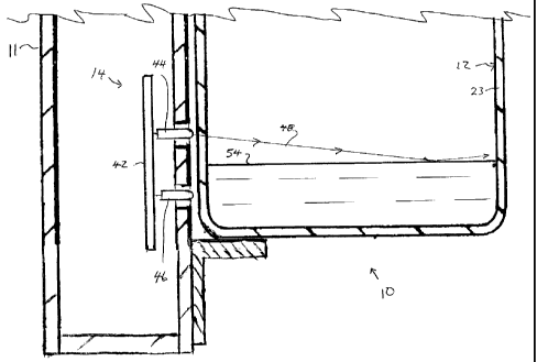
and automatic dispensers in requiring recognition as to when a bottle has been
coupled to the
dispenser, and recognition when a bottle that is coupled to the dispenser is
full so as to
represent an initiation point for counting. Such arrangements have been found
to be
1
CA 02739362 2011-05-06
disadvantageous in providing a requirement for having bottle sensing
arrangements separate
from mechanisms which may recognize the activation of the pump.
Summary of the Invention
[0004] To at least partially overcome these disadvantages of previously known
devices,
the present invention provides a fluid level gauging mechanism external of a
reservoir bottle
in a dispenser which mechanism emits electromagnetic radiation and senses the
electromagnetic radiation emitted which passes through the bottle or is
reflected from the
bottle4hrough a ~)alIof the bottle into the bottle. at a first height and
senses reflected
radiation passing outwardly from the bottleaa seond different height.
[0005] An object of the present invention is to provide a simplified fluid
level gauge for
estimating the fluid level within a reservoir bottle.
[0006] Another object is to provide a fluid level gauge mechanism for
estimating the
fluid remaining in both bottles which collapse when fluid is discharged and
bottles which do
not collapse.
[0007] Another aspect of the present invention provides an arrangement useful
for
determining levels of fluids in bottles or other containers within dispensers
whether the
bottles or containers be collapsible or substantially not collapsible or
rigid.
[0008] In the context of a rigid bottle, the preferred invention utilizes a
path for the
radiation which extends through the fluid within the bottle such that
differences in radiation
sensed will vary depending upon the extent that the path for the radiation is
either through the
fluid in the bottle or through gas or air in the bottle above the fluid. The
radiation path may
merely pass merely once directly through the bottle without being reflected or
may be a
reflected path in which radiation is reflected and redirected preferably being
reflected back
through the bottle. In the context of a collapsible bottle, the radiation path
is preferably
selected such that the path intersects with portions of the bottle in some
conditions and, in
other conditions, the path does not intersect with portions of the bottle. The
radiation path
for a collapsible bottle may also be a path which requires the radiation to
pass through fluid
in the bottle. In the context of a collapsible bottle, either the reflection
of radiation or a
reduced transmission of radiation can be used to sense the presence of a
portion of a bottle in
2
CA 02739362 2011-05-06
a radiation path as contrasted with less or no radiation being sensed being
indicative of an
absence of a portion of a bottle in the radiation path. A radiation path can
be selected such
that reflection of radiation from the interior or exterior of a wall of a
bottle can be used as an
indication of an alteration of the shape of a collapsible bottle.
[0009] In accordance with a first aspect of the present invention, the present
invention
provides a fluid level gauging mechanism for estimating fluid levels in a
bottle and
which mechanism includes a controller,
controlling operation so as to periodically and successively perform:
(i) a step of emitting radiation with an emitter and simultaneously sensing
the
relative level of radiation received by a sensor to determine a sensed
radiation value,
(ii) comparing the sensed radiation value in one step (i) to a compared value
selected from a pre-selected value and sensed values sensed in another steps
(i), and
(iii) identifying when a significant change in the sensed radiation values
occurs, and characterizing the significant change in the sensed radiation
values as an
indication of the level of fluid in the bottle.
[0010] In accordance with a second aspect of the present invention, the
present invention
provides a dispenser comprising:
a housing,
a bottle containing fluid to be dispensed,
a pump mechanism to dispense fluid from the bottle,
the bottle removably coupled to the housing for replacement,
the bottle having a wall defining a cavity therein within fluid is contained,
the
wall having an exterior surface and an interior surface, the interior surface
facing
the cavity,
the housing carrying a fluid level gauging mechanism to estimate the level of
fluid in the bottle,
the fluid level gauging mechanism comprising:
an emitter of electromagnetic radiation within a range of wavelengths, and
a sensor of electromagnetic radiation within the range of wavelengths,
3
CA 02739362 2011-05-06
the wall of the bottle including window portions permitting electromagnetic
radiation within the range of wavelengths to pass through the wall, the window
portions
including an inlet window and an outlet window,
wherein when the bottle is coupled to the housing:
the emitter is located outside the bottle exterior of the exterior wall
positioned to
direct the electromagnetic radiation into the bottle through the inlet window,
and
the sensor is located outside the bottle exterior of the exterior wall to
receive
electromagnetic radiation from emitter which is reflected within the bottle to
pass outwardly
through the outlet window,
wherein in operation the emitter directing radiation into the bottle through
the
inlet window and the sensor receiving radiation from the emitter reflected
from within the
bottle out through the outlet window. Preferably, the emitter is carried on
the housing at an
emitter vertical height, and the sensor carried on the housing at a sensor
vertical height
different than the emitter vertical height. The inlet window is located
relative the housing at
an inlet vertical height and an outlet window is located relative the housing
at an outlet
vertical height different than the inlet vertical height
[0011] Preferably, the electromagnetic radiation is infrared radiation, the
bottle has a wall
of plastic material translucent to the electromagnetic radiation. Preferably,
the bottle carries
a label on a wall of the bottle which assists in reflecting radiation emitted
into the bottle
towards a position where the radiation is to be sensed.
Brief Description of the Drawings
[0012] Further aspects and advantages of the present invention will become
apparent
from the following description taken together with the accompanying drawings
in which:
[0013] Figure 1 shows a fluid dispenser in accordance with a first embodiment
of the
invention;
[0014] Figure 2 is an exploded view of the dispenser of Figure 1 showing the
housing,
the pump mechanism and the bottle;
[0015] Figure 3 is a schematic cross-sectional side view of the dispenser of
Figure 1;
4
CA 02739362 2011-05-06
[0016] Figure 4 is a cross-sectional top view of Figure 3 along section line 4-
4' in Figure
3 schematically showing merely the bottle and the fluid level gauge mechanism;
[0017] Figure 5 is a schematic cross-sectional side view along section line 5-
5' in Figure
4 view showing the fluid level gauge mechanism;
[0018] Figures 6, 7 and 8 each is a schematic cross-sectional side view
similar to Figure
and showing respectively conditions in which the level of fluid in the bottle
is, respectively,
above both the IR emitter and sensor, intermediate the IR emitter and sensor,
and below the
IR emitter and sensor;
[0019] Figure 9 is a schematic diagram of a control mechanism for the
dispenser of
Figure 1;
[0020] Figure 10 is a chart plotting the fluid height in a bottle versus the
reflected
radiation sensed;
[0021] Figure 11 is a schematic cross-sectional view similar to Figure 6 but
showing a
second embodiment of a dispenser in accordance with the present invention;
[0022] Figure 12 is a schematic cross-sectional view similar to Figure 6 but
showing a
third embodiment of a dispenser in accordance with the present invention;
[0023] Figure 13 is a schematic cross-sectional view similar to an upper
portion of Figure
3 but showing a fourth embodiment of a dispenser in accordance with the
present invention;
[0024] Figure 14 is a schematic cross-sectional view similar to an upper
portion of Figure
3 but showing a fifth embodiment of a dispenser in accordance with the present
invention;
[0025] Figures 15, 16, 17 and 18 are schematic pictorial views showing
alternate
arrangements for radiation from an emitter to be reflected from a wall for
sensing by a
sensor;
[0026] Figure 19 is a schematic cross-sectional view similar to Figure 4 but
showing a
sixth embodiment of a dispenser in accordance with the present invention with
the emitter
and the sensor located at the corners of the bottle;
[0027] Figure 20 is a schematic vertical cross-sectional view along section
line A-A' in
Figure 19;
5
CA 02739362 2011-05-06
[0028] Figure 21 is schematic cross-sectional view similar to Figure 4 but
illustrating a
seventh embodiment of a dispenser in accordance with the present invention
using light
guides;
[0029] Figure 22 is a pictorial front view of a bottle and pump assembly for
use with a
dispenser in accordance with an eighth embodiment of the present invention;
[0030] Figure 23 is a pictorial rear view of the bottle shown in Figure 22;
[0031] Figure 24 is a schematic cross-sectional side view of a dispenser in
accordance
with an eighth embodiment of the present invention and identical to that shown
in Figure 3
but with the bottle and pump assembly of Figure 22 substituted for the bottle
and pump
mechanism from Figure 3 and showing the bottle filled with fluid to be
dispensed;
[0032] Figure 25 is a schematic cross-sectional view of the eighth embodiment
of the
dispenser shown in Figure 24, however, with the bottle substantially
collapsed;
[0033] Figure 26 is an enlarged cross-sectional side view of the pump
mechanism as seen
in Figure 24;
[0034] Figure 27 is a front view of the bottle in a full condition as seen in
Figure 24;
[0035] Figure 28 is a front view of the bottle in a collapsed position as seen
in Figure 25;
[0036] Figure 29 is a cross-sectional side view of the bottle and pump
assembly shown in
Figure 24 along center line B-B' in Figure 24 showing, however, the bottle in
a full condition,
a partially collapsed condition and a fully collapsed condition;
[0037] Figure 30, on the sheet with Figure 28, is a cross-sectional top view
through the
collapsed bottle shown in Figure 25 along section line C-C';
[0038] Figure 31 is a cross-sectional top view of the dispenser of Figure 24
along section
line D-D' in Figure 24;
[0039] Figure 32 is a schematic vertical cross-sectional side view along
section line E-E'
in Figure 31;
[0040] Figure 33 is a cross-sectional side view the same as Figure 32,
however, showing
the bottle in three successively collapsed positions;
[0041] Figure 34 is a cross-sectional view similar to Figure 33, however,
showing an
eleventh embodiment which has an alternate arrangement for emitters and
sensors; and
6
CA 02739362 2011-05-06
[0042] Figure 35 is a cross-sectional view similar to Figure 34, however,
showing a
twelfth embodiment.
Detailed Description of the Drawings
[0043] Figures 1 and 2 show a fluid dispenser 10 in accordance with the
present invention
having a housing 11, a removable bottle 12, and a pump mechanism 13, with a
fluid level
sensing mechanism 14 only seen in Figure 2. The housing 11 carries a removable
shroud 15.
The pump mechanism 13 is activated by an activation lever 16.
[0044] The dispensing unit 10 is shown in Figure 3 as mounted to a wall 95.
[0045] The dispenser 10 is adapted to be manually activated by a user urging
the activation
lever 16 downwardly so as to dispense fluid from a discharge outlet 17 onto a
hand of a user
disposed underneath.
[0046] The bottle 12 is closed at its bottom or lower end 18. Sides 19 of the
bottle 12
extend upwardly from the lower end 18 to an upper end 20 having top or
shoulder 24 merging
into an upstanding neck 21 carrying an opening 22. The sides 19 are
characterized as a front
side, rear side, right side and left side. The bottle 12 has a thin wall 23
which forms the lower
end 18, sides 19, shoulder 24 and the neck 21. The wall 23 defines a cavity 25
within the bottle
12 within which fluid 98 to be dispensed is contained. As seen in Figure 3,
the wall 23 has an
outwardly directed exterior surface 26 and an interior surface 27 which faces
inwardly into the
cavity 25.
[0047] The housing 11 has a rearmost vertical wall plate 28 and a vertical
back plate 29.
The wall plate 28 is adapted to be secured to the wall 95. Side plates 30 and
31 extend along
each side of the wall plate 28 and the back plate 29 forwardly in parallel
vertical planes. A
horizontal top plate 32 extends forwardly on top of the wall plate 28 and the
back plate 29
forwardly between the side plates 30 and 31. A horizontal bottom plate 33
extends forwardly
below the wall plate 28 and the back plate 29. A compartment 34 is defined
rearward of the
back plate 29 between the wall plate 28 and the back plate 29, between the
side plates 30 and 31
and between the top plate 32 and the bottom plate 33. A horizontal bottle
support bracket 35 is
provided extending along the back plate 29 bridging between side plates 30 and
31 and
presenting an upwardly directed support surface 41 to engage and support the
bottle 12. The
7
CA 02739362 2011-05-06
housing 11 also has a pump support plate 42 which extends forwardly from the
back plate 29
between the side plates 30 and 31 to support the pump mechanism 13.
[0048] As seen in Figures 4 and 5, the fluid level gauging mechanism 14 is
schematically
illustrated as comprising a rectangular circuit board 42 carrying an infrared
emitter 44 and an
infrared sensor 46. The circuit board 42 is carried by the housing 11 within
the compartment 34
rearward of the back plate 29. Two vertically spaced openings 45 and 47 are
provided through
the back plate 29. The emitter 44 is located to extend through the upper
opening 45 and the
sensor 46 is located to extend through the other, lower opening 47, such that
each of the emitter
44 and the sensor 46 is disposed rearward of the exterior surface 26 of the
wall 23 of the rear
side of the bottle 12. The wall 23 of the rear side of the bottle 12 in front
of each of the emitter
44 and the sensor 46 permits IR radiation within the range of wavelengths
emitted by the IR
emitter 44 and sensed by the IR sensor 46 to pass through the wall 23.
[0049] Each of the emitter 44 and sensor 46 is located outside the bottle 12,
exterior of the
exterior surface 27 of the wall 23 of the rear side of the bottle 12. The
emitter 44 is positioned
to direct JR radiation into the cavity 25 within the bottle 12 and the sensor
46 is located to
receive IR radiation from the emitter 44 which is reflected from within the
cavity 25 within the
bottle and passes outwardly from the cavity 25 through the wall 23 of the rear
side of the bottle.
In operation, the emitter 44 directs radiation into the bottle 12 through the
wall 23 of the rear
side and the sensor 46 receives radiation from the emitter 44 which is
reflected within the bottle
12 and passes from the cavity 25 out of the cavity through the wall 23 of the
rear side of the
bottle.
[0050] As shown in side view in Figure 5, the emitter 44 is at a vertical
height above the
sensor 46. IR radiation from the emitter 44 is shown to extend along a path
indicated by arrows
48 to travel through the wall 23 of the rear side of the bottle into the
cavity 25 to traverse the
cavity 25 to engage the wall 23 of the front side of the bottle 12 on a
diametrically opposite the
rear side of the bottle 12 and to be reflected on a path shown by the arrows
49 to traverse the
cavity 25 and travel through the wall 23 of the rear side out of the cavity 25
to be sensed by the
sensor 46. In top view as seen in Figure 4, the path of the radiation shown by
the arrows 48 and
49 in Figure 5 are shown by the double headed arrows 50.
8
CA 02739362 2011-05-06
[0051] In Figures 3 and 6 to 8, the level of fluid in the bottle is indicated
as 54. With
activation of the pump mechanism 13, the fluid level 54 in the bottle 12 will
decrease as from a
relatively full condition as shown in Figure 3 successively to the conditions
shown in Figure 6,
Figure 7 and Figure 8 with the fluid level 54 progressing from heights above
the emitter 44, to
the same height as the emitter 44, to below the emitter 44 and above the
sensor 46, to the same
height as the sensor 46 and then to below the sensor 46.
[0052] As seen in Figure 9, the fluid level gauging mechanism 14 includes a
control
mechanism 55 to control the operation of the emitter 44 and the sensor 46. The
control
mechanism 55 operates the emitter 44 to emit electromagnetic radiation within
a specific range
of wavelengths and simultaneously operates the sensor 46 to sense
electromagnetic radiation
representative of the radiation emitted, preferably within the same specific
range of wavelengths
as the radiation emitted by the emitter 44. Preferably, the electromagnetic
radiation emitted is
infrared radiation and the sensor 46 senses infrared radiation of the same
wavelength as emitted.
Preferably, the radiation is emitted by the emitter 44 periodically for short
intervals as
individual bursts so as to minimize power consumption. The radiation sensed by
the sensor 46
as in any burst may be compared to the radiation emitted so as to determine a
relative extent to
which the radiation emitted by the emitter 44 is received by the sensor 46.
The relative
radiation sensed by the sensor 46 for any burst is compared to either a pre-
established threshold
radiation or to the relative radiation sensed by the sensor 46 in other
bursts.
[0053] Figure 9 schematically illustrates the control mechanism 55 as
including a controller
80 which interfaces with the emitter 44 and the sensor 46, as well as a power
source 81, a
communication module 82 and a data storage module 83. The control mechanism 55
is also
shown as including an optional status indicator 84, and an optional remote
computer 85.
[0054] Reference is made to Figure 10 which is a graph illustrating the fluid
height of the
fluid level 54 in the bottle versus the relative level of radiation sensed by
the sensor 46 when a
constant level of radiation is emitted by the emitter in each successive burst
of radiation. The
fluid height is indicated as a percentage of the height of fluid in a full
bottle. The relative
vertical height of the emitter 44 is indicated as E and the relative vertical
height of the sensor 46
is indicated as S. In the preferred first embodiment, a mid-point between the
emitter vertical
height E and the sensor vertical height S is a fluid height corresponding to
about 10 percent of
9
CA 02739362 2011-05-06
the height of fluid in the bottle. With a bottle assumed to have a constant
cross-sectional shape
throughout its height, this 10 percent height of fluid in the bottle
represents a fluid level
corresponding to about 10 percent of the volume of the bottle.
[0055] Figure 10 shows in a solid line the radiation sensed by the sensor 46
when the bottle
is filled with a first fluid comprising as an alcohol based hand cleaner, an
aqueous solution of
alcohol comprising about 60 percent alcohol and 40 percent water. Figure 10
shows in a dashed
line the radiation sensed by the sensor 46 when the bottle is filled with a
second fluid
comprising a typical soap based cleaner comprising an aqueous solution of
water and soap
having the following composition which is less transmissive of IR radiation
than the aqueous
solution of alcohol of the first fluid.
[0056] In each fluid, the infrared radiation used is in the range of X to Y.
With such
radiation, the alcohol based cleaner transmits the radiation to a greater
extent than the soap
based cleaner. As is to be appreciated, the level of reflection is
substantially constant for each
liquid as the fluid level 54 decreases downwardly from being substantially
full to a point where
the fluid level is above the emitter vertical height E in a condition as
indicated in Figure 6. As
is expected, when the fluid level 54 is intermediate the emitter vertical
height E and the sensor
vertical height S in a condition indicated in Figure 7, the sensed radiation
is at a minimum.
When the fluid level 54 is below the sensor vertical height S, the sensed
radiation rises to a
maximum representing the radiation that is reflected back after passage
through air in the bottle
in a condition as indicated in Figure 8. In the case of the soap based
cleaner, the relative level
of sensed radiation when the level is below the sensor vertical height S is
substantially greater
than the relative level of radiation emitted when the fluid height 54 is above
the emitter vertical
height E. In contrast, the alcohol based cleaner transmits the radiation to a
greater degree and
thus the reflected radiation of the alcohol based cleaner when the fluid level
54 is below the
sensor vertical height S is much closer to the sensed radiation when the fluid
height 54 is above
the emitter vertical height E.
[0057] As seen in Figure 10, the IR response represented by the radiation
sensed is
indicated as having three portions, an above portion 100 over which the
radiation sensed is
substantially constant at approximately a first level, a below portion 104
over which the
radiation is substantially constant at a relatively high level and an
intermediate portion 102 over
CA 02739362 2011-05-06
which the radiation sensed changes rapidly. The intermediate portion includes
a decreasing
segment 101 and an increasing segment 103.
[0058] The control mechanism 55 will take readings of the radiation sensed
over time and
by a comparison of the radiation sensed over time make a determination as to
where the fluid
level is. It will be appreciated to a person skilled in the art that this can
be accomplished in a
number of ways. For example, from a number of data points from the above
portion 100, on
obtaining readings which deviate significantly from the above portion
readings, and are less
than the above portion readings, then an estimate can be made that the fluid
level is in the
intermediate portion 102. Alternatively, the relative change of the sensed
radiation level with
time can be used so as to determine the relative change between readings over
the above portion
100 as contrasted with the relative change in the intermediate portion 102 and
identify the
intermediate portion 102 by reason of a greater change per time or activation.
[0059] Various algorithms may be established depending upon the number of
readings
which are to be taken and the extent to which data of the readings may be
maintained and stored
and be accessible over time.
[0060] The radiation sensed can also be useful for determining a condition
that no bottle is
present as, for example, by providing a consistent reading in which there is
no substantially no
reflected radiation received. The reflected radiation would not be received,
for example, if no
bottle was present and the dispenser did not have a front cover to its
housing. Adjustments can
be made to avoid false readings due to ambient radiation.
[0061] The system can be used to determine if a bottle which is not intended
for use with
the dispenser has been inserted into the dispenser. For example, as seen in
Figure 11, a bottle
for use with the invention may be provided with customized labels such as a
customized rear
label 72 with an inlet window 73 and an outlet window 74 located,
respectively, relative to the
emitter 44 and the sensor 46. Products which may have labels which cover where
inlet window
73 and outlet window 74 are to be provided would not have radiation sensed by
the sensor 46
and thus provide an indication that an erroneous bottle may have been
inserted. As will be
appreciated, by the relative location of the emitter and sensor at different
heights and different
locations and corresponding labels 72 being provided with appropriate inlet
windows 73 and
outlet windows 74, a system for keying of specifically labelled bottles to
specific dispensers
11
CA 02739362 2011-05-06
may be adopted so as to signal use of a bottle other than a bottle as intended
in any particular
dispenser.
[0062] As seen in Figure 9, the control mechanism 55 optionally includes a
remote
computer 85. Under this configuration, the components comprising the control
mechanism 55
that are provided within the dispenser may make data readings and transmit
data to the remote
computer 85 with the remote computer 85, for example, to perform calculations.
In a preferred
embodiment, communication is from the communication module 82 merely one way
to the
computer with the remote computer 85 to perform calculations to determine when
the dispenser
may be substantially empty and thus via the computer system send a message as
to a worker
that the bottle for the fluid dispenser is close to empty and should be
replaced or refilled.
However, the communication may be two way as to provide communication from the
computer
85 back to the controller 80 in the dispenser 10 as, for example, to activate
a warning light 85
on the dispenser that the dispenser is close to empty.
[0063] The control mechanism 55 is indicated as having a data storage module
83 which
can store varying amounts of data depending upon the nature of the operation
of the dispenser.
Insofar as information for data reading is to be sent to a remote computer,
then the size and
capability of the data storage module 83 may be minimal. Insofar as the
control mechanism 55
as contained within the dispenser 10 may itself desire to make calculations,
then the size of the
data storage module 83 and its capability may need to be increased.
[0064] As to the nature of the power supply 81, the dispenser 10 may be a
manually
operated dispenser or may be an automated dispenser with a power source
driving the pump to
dispense fluid as, for example, when activated by a switch which may comprise
a manually
operated switch or, more preferably, a touchless arrangement in which the
proximity of a
person's hand to the dispenser operates a dispenser. In an automated dispenser
which is
preferably touchless, the power source may comprise a battery or other power
source as, for
example, 12 volt or 115 volt with the dispenser hardwired to the power source.
With a
manually operated dispenser, the control mechanism 55 may be powered
preferably by batteries
which batteries or another power storage device may in a preferred embodiment
may be
recharged as, for example, by a solar battery charger or by a generator which
provides power on
manual movement of the activation lever 16. In a preferred embodiment of the
present
12
CA 02739362 2011-05-06
invention, the dispenser is manually operated with those portions of the
control mechanism 55
within the dispenser operating with minimum power consumption for transmission
of data from
the communication module 82 to a remote computer system.
[0065] As to the nature of the fluid within the bottle, there is no particular
limit, however,
the fluid for the first embodiment needs to be selected to be a fluid which
will permit selected
electromagnetic radiation to pass therethrough and be reflected by the front
of the bottle back to
the sensor 46. It is within the scope of persons skilled within the art to
select a suitable
wavelength of electromagnetic radiation and the particular fluid for use in
the bottle. Preferred
electromagnetic radiation includes infrared radiation preferably with
wavelengths in the range
of X to Y. These wavelengths are useful for transmission through many
commercially available
alcohol based hand cleaners and soap based hand cleaners.
[0066] As to the nature of the material from which the bottle 12 and its wall
23 is formed,
preferred materials include glass and plastic materials with preferred plastic
including
polyethylene plastics. It is within the knowledge of a person skilled in the
art to make a suitable
selection as to the nature of the material for the wall of the bottle so as to
permit suitable
transmission of the selected radiation therethrough.
[0067] The wall 23 of the bottle 12 may have the same composition and
thickness
throughout the entirety of the bottle or may have selective composition and
thickness over
window portions and the reflecting portion.
[0068] On Figure 6, window portions of the wall 23 of the rear side of the
bottle 12 in front
of the emitter 44 and the sensor 46 which are indicated as 300 and 301,
respectively, are the
only portions of the wall 23 which need to have an ability to permit radiation
to pass
therethrough. Similarly, a reflective portion 302 on the wall 23 of the front
side of the bottle 12
is the only portion that needs to be at least partially reflective. The nature
of the wall 23 may be
such that over the window portions 300 and 301 merely a portion of the
radiation passes
through and some is reflected. The wall 23 may have the same composition and
thickness
throughout the entirety of the bottle or may have selective composition,
thickness and/or
reflective properties over the window portions 300 and 301 and the reflecting
portion 302.
[0069] The ability of the wall 23 to transmit and/or reflect radiation can be
modified over
the window portions 300 and 301 and reflective portion 302 a number of ways.
13
CA 02739362 2011-05-06
[0070] As seen in an embodiment of a bottle 12 shown in Figure 11, a front
label 70 is
applied to the exterior surface of the wall 23 of the front side of the bottle
12. This label 70
covers the exterior surface 26 of the wall 23 over a reflection portion 302
where IR radiation
from the emitter 44 engages the wall 23 along path 48 and is reflected back to
the sensor 46
along path 49. The front label 70 is optional, however, the front label 70 may
preferably be
provided to increase the extent to which IR radiation from the emitter 44 is
reflected from the
front side 53 of the bottle. The front label 70, for example, may have a
reflective rear surface,
for example, of an aluminum foil.
[0071] The emitter 44 is carried on the housing 11 at a height referred to as
an emitter
vertical height E and the sensor 46 is carried on the housing 11 at a height
referred to as the
sensor vertical height S. The sensor vertical height S in some preferred
embodiments is
different than the emitter vertical height E. For example, in the preferred
first and second
embodiments, the emitter 44 is above the sensor 46, that is, with the emitter
vertical height E
greater than the sensor vertical heights. However, the sensor 46 may be above
the emitter 44.
[0072] A rear label 72 is shown in Figure 11 applied to the exterior surface
of the wall 23 of
the rear side of the bottle 12. The rear label 72 has openings therethrough in
front of each of the
emitter 44 and sensor 46, respectively, which openings are an inlet opening
303 in front of the
emitter 44 and an outlet opening 305 in front of the sensor 44.
[0073] The bottle may be chosen to have suitable physical arrangements so as
to enhance,
on one hand, transmission of light therethrough on the rear side and
reflection on the front side
53. For example, to enhance transmission, over the area of the inlet window
300, the wall 23 on
the rear side may be disposed to be perpendicular to radiation emitted from
the emitter 44 and
similarly over the outlet window 301 the wall 23 on the rear side may be
disposed to be
perpendicular to light reflected from the front side. Towards increasing
reflection or focussed
reflection, the reflective portion 302 of the wall 23 on the front side may
have a shape to
optimize reflection as, for example, by having a convex surface which acts as
a lens to direct
light engaged thereon towards the sensor 46 at least over an area which is
intermediate the
emitter height E and the sensor height S. In this regard, reference is made to
Figure 12 which
illustrates a third embodiment in a side view similar to that shown in Figure
6, however, in
which each of the sensor 46 and the emitter 44 have been disposed so as to
direct radiation
14
CA 02739362 2011-05-06
parallel their respective lines 48 and 49. Each of the inlet window 300 in
front of the emitter 44
and the outlet window 301 in front of the sensor 46 is shown to comprise a
relatively thin
portion of the wall 23. The inlet window 300 has its exterior surface 26 and
interior surface 27
each disposed to be perpendicular to the path 48. The outlet window 301 is
shown to have its
exterior surface 26 and interior surface 27 perpendicular to the path 49. The
reflected portion
302 is shown to have both an interior surface 27 and an exterior surface 26
which are curved so
as from the inside each provides a concave surface. A front label 70 is shown
applied which
includes a reflective section 306 with a mirrored interior surface to assist
in reflecting radiation
over merely the reflective portion 302. This third embodiment also illustrates
an arrangement in
which the sensor 46 is disposed at a height above the emitter 44.
[0074] The activation lever 16 comprises a continuous length of metal rod
having two Z-
shaped side arm portions 56 and 57 joined by a centre bridging bar 58. Each of
the side
portions 56 and 57 are pivotally coupled at their rear end 59 to the
respective side plates 30 and
31 for pivoting about the same horizontal axis 60. A spring member 61 is
disposed between
support plate 42 and the actuation lever 16 so as to bias the actuation lever
16 to pivot about the
axis 60 counter-clockwise as seen in Figure 3.
[0075] Figure 3 illustrates an extended position in which the spring 61 has
biased the
actuation lever 16 as far counter-clockwise as possible. From the extended
position of Figure 3,
a user may engage the bridge portion 58 of the activation lever 16 and move
the activation lever
16 downwardly against the bias of the spring 61 to a retracted position. On
manual release of
the activation lever 16 from the retracted position, the spring 61 moves the
activation lever 16 to
the extended position as shown in Figure 3.
[0076] The pump mechanism 13 is schematically illustrated as having a piston
chamber-
forming tube 62 fixedly secured in an opening through the pump support plate
42 to extend
downwardly and carrying a dip tube 63 fixedly secured in sealed relation and
angled slightly
forwardly. A piston member 64 is provided coaxially vertically slidably
received within the
piston chamber-forming tube 62 and biased upwardly by an internal pump spring
65. An upper
end 66 of the piston member 64 engages with the actuation lever 16 via the
bridging bar 58
extending between the side arm portions 56 and 57 such that the actuation
lever 16 in movement
from the extended to the retracted position will displace the piston member 64
axially into the
CA 02739362 2011-05-06
piston chamber-forming tube 62 against the bias of the pump spring 65 to
displace fluid through
a central axial discharge passageway 68 in the piston member 64 which connects
to the hollow
interior of a discharge tube 69 so as to discharge fluid from the outlet 17.
The piston member
64, discharge tube 62, and outlet 17 together move upwardly and downwardly
relative the pump
support plate 42. Such pump mechanisms are well known to include one-way
valves and seals
to provide proper pumping, however, for ease of illustration are not shown.
[0077] With movement of the activation lever 16, a dose amount of fluid is
discharged from
the outlet 17. With repeated activation of the pump mechanism fluid in the
bottle 12 is
dispensed out the outlet 17 and the level of fluid 54 in the bottle 12 will
decrease as from the
condition with a fluid level 54 at a height below the height of the emitter 44
but above the
height of the sensor 46 as seen in Figure 6 to a condition with the fluid
level 54 at a height
below the height of the sensor 44 as seen in Figure 8.
[0078] The opening 22 of the bottle 12 is shown as disposed loosely about the
piston
member 64 and providing for communication between the atmosphere and the
interior of the
bottle. The bottle 12 may readily be removed by the lower end 18 of the bottle
12 being moved
forwardly of the bottle support bracket 35. The dip tube 63 is preferably
tilted forwardly to
assist in permitting the bottle 12 to be slid vertically and rearwardly on to
and off of the dip tube
63. The bottle 12, when in use, merely rests on the bottle support bracket 35
and may, to some
extent, tip forwardly, for example, until the neck 21 may engage on the piston
member 64.
[0079] The preferred embodiment in Figures 1 to 7 has been illustrated with a
schematic
pump mechanism 13 which is secured to the pump support plate 42 and not to the
bottle 12. It is
appreciated that many other removable and non-removable bottles and pumping
mechanisms
may be provided including those in which the pump mechanism is fixedly secured
to the bottle
and removable with the bottle. The particular nature of the pump mechanism 13
formed by the
piston chamber-forming tube 62 and the piston member 64 is not essential and
many different
pump mechanisms may be adopted as known to persons skilled in the art.
[0080] Figure 13 illustrates an embodiment of the invention which is identical
to the first
embodiment of Figures 1 to 7 with the exception that an electrical power
generator 120 is
coupled to the end 118 of a rigid extension 119 of the actuator 16 such that
manual movement
of the actuator 16 creates electrical power by deflecting a piezoelectric
harvester 150 as in the
16
CA 02739362 2011-05-06
manner of that described in the applicant's co-pending US Patent Publication
US 2010/0288788
published November 18, 2010 which is incorporated herein by reference. The
electrical power
generated by manual movement of the actuator 16 is used to operate the
controller mechanism
55 and/or to charge any power sources.
[0081] Figure 14 illustrates an embodiment of the invention which is identical
to the first
embodiment of Figures 1 to 7 with the exception that it is adapted for
automated dispensing by
providing an electric motor to rotate a wheel 122 about an axis 124 with an
eccentric cam pin
125 carried on the wheel 122 coupled by a link 124 to an end 118 of a rigid
extension 119 of the
actuator to dispense fluid as activated by an activation switch, such as a
manually operated
switch carried on the cabinet 11 or a hand sensing switch disposed, for
example, on the shroud
15 to sense a user's hand underneath the dispenser 10 vertically below the
outlet 17.
[0082] In each of the first, second and third embodiments, the fluid level
gauging
mechanism 14 is shown as comprising a single circuit board 42 with a single
emitter 44 and a
single sensor 46 and in which the emitter 44 and sensor 46 are disposed at
different vertical
heights. Reference is made to Figures 15 to 18 which schematically illustrate
a number of
different configurations for the fluid level gauging mechanism 14. Each of
Figures 15 to 18
schematically illustrate the wall 23 of the front side of the bottle spaced
from a circuit board 42
carrying an emitter 44 and at least one sensor 46. For convenience, in Figures
15 to 18, each
emitter is shown as a circle on each circuit board and each sensor is shown as
a rectangular on
each circuit board.
[0083] In Figure 15, a circuit board 42 carries the emitter 44 vertically
above the sensor 46
in a manner substantially identical to that illustrated in the first, second
and third embodiments.
However, the circuit board 42 also carries a secondary sensor 46a disposed
vertically above the
emitter 44. The radiation received by the sensor 46 can determine when the
liquid level is at a
height intermediate the emitter 44 and the sensor 46. The radiation received
by the sensor 46a
can determine whether the fluid is at a height between the sensor 46a and the
emitter 44. Thus,
by providing a plurality of sensors at different locations relative to one
emitter, that is,
preferably at different heights as shown, the level gauging mechanism 14 can
provide
indications as to different heights of fluid in a bottle.
17
CA 02739362 2011-05-06
[0084] Reference is made to Figure 16 which shows the emitter 44 as a circle
and the sensor
46 as a rectangle coincident on the circle as in the case when a single
element may serve a dual
purpose of being both a sensor 46 and an emitter 44 located at the same
location. In Figure 16,
the emitted radiation extends towards the wall 23 along the same path 131 that
the reflected
radiation travels. The arrangement in Figure 16 can be used in each of the
first, second and
third embodiments to sense the fluid level, however, will provide in the
context of a chart
shown in Figure 10 a much sharper transition in the plot of fluid height in a
bottle versus
reflected radiation sensed. Figure 16 also schematically illustrates a cone
130 representing the
radiation as emitted from the emitter 44 as it travels outwardly from the
emitter 44. Different
emitters may irradiate radiation at different angles about a center line 131
and a relative angle of
the cone 130 of emission may be selected to be narrower or wider having regard
to the surfaces
from which radiation is desired to be reflected.
[0085] Reference is made to Figure 17 which shows an arrangement with the
circuit board
42 carrying an emitter 44 and two horizontally spaced sensors 46 and 46a,
however, in this case
with the sensor 46a further from the emitter 44 than the sensor 46.
[0086] Reference is made to Figure 18 which shows an arrangement the same as
in Figure
15, however, with a second circuit board 42a spaced to one side beside the
first circuit board 42.
The second circuit board 42a is shown as carrying three additional sensors
46b, 46c and 46d.
Radiation from the emitter 44 may be received by each of the sensors 46, 46a,
46b, 46c and 46d,
however, reflective paths are shown merely for radiation to be received by
sensors 46b and 46d.
[0087] Reference is made to Figures 19 and 20 which illustrate views of a
fourth
embodiment of a dispenser in accordance with the present invention. Figures 19
and 20
comprise, respectively, a top cross-sectional view and a side cross-sectional
view substantially
the same as those shown in Figures 15 and 16 with the first embodiment. The
fourth
embodiment of Figures 19 and 20 differs from the first embodiment of Figures 4
and 5 in that
the emitter 44 and the sensor 46 are each disposed adjacent a rear corner of
the bottle 12,
outwardly of a rear label 72 carried on the exterior surface of the wall 23 on
the rear side of the
bottle 12. The sensor 46 and emitter 44 are shown at respective rear corners
307 and 308 at
locations which avoids the label 72. Figure 20 is a schematic side view of the
embodiment
shown in Figure 19 along section line A-A'. Along this section line A-A',
neither of the emitter
18
CA 02739362 2011-05-06
44 or the sensor 46 would be seen and thus, for convenience of illustration,
the relative height
and location of the emitter 44 and sensor 46 is shown and, as well, the label
42 shown as cut
away. Further, the dip tube 63 is not shown in cross-section. In Figures 19
and 20, three
different paths for radiation emitted from the emitter 44 are shown by which
radiation may be
reflected internally within the bottle 12 so as to be received by the sensor
46. A first path
indicated by the longest arrows 141 is reflected off the wall 23 of the bottle
12 on the
diametrically opposite front. A second path shown by intermediate length
arrows 142 is
reflected off a bulbous concave end 139 of the dip tube 63. A third path shown
by the shortest
arrows 143 is reflected off a cylindrical stem 140 of the dip tube 63. It is
to be appreciated that
in order to have reflection along all three reflective paths, then the cone of
emission from the
emitter 44 needs to be directed at a sufficient angle to include each of the
two most divergent
paths, second and third paths represented by arrows 142 and 143. As a variant,
the emitter 44
may have a smaller cone of emission and, for example, merely provide for
emission along the
first and second paths indicated by arrows 141 and 142.
[0088] The arrangement illustrated in the seventh embodiment of Figures 19 and
20 is
advantageous so as to permit the bottle 12 to carry a rear label 72 provided
the label 72 does not
extend as far as the rear corners 307 and 308 where the emitter 44 and sensor
46 are located.
The arrangement also has the advantage of permitting the mechanism 14 to
determine whether
or not the dip tube 63 is present and to determine the nature of the dip tube
63. For example,
the dip tube 63 could have different configurations providing for increased or
decreased
reflection and the dip tube 63 may be chosen to have surfaces which, to
different extents, reflect
or absorb the radiation be emitted. Thus, by suitable selection of the
radiation emitted, the
configuration or reflectance or absorbency of the dip tube, determinations can
be made from the
reflected radiation sensed as to which dip tube may be present. By having the
nature of a dip
tube correlate to a particular bottle 12 or a particular fluid within a bottle
12, the mechanism 14
may thus provide feedback as to the nature of the dip tube and its associated
bottle and/or fluid.
[0089] Reference is made to Figure 21 which illustrates a seventh embodiment
of a
dispenser in accordance with the present invention. Figure 21 is a cross-
sectional top view
substantially the same as Figure 4, however, with the notable difference that
the circuit board 42
and the emitter 44 and sensor 46 now comprise a vertically disposed circuit
board 42 carrying
19
CA 02739362 2011-05-06
the emitter 44 and the sensor 46 on opposite sides each disposed away from
each other. An
emitter light guide 146 and a sensor light guide 147 are provided. The emitter
waveguide 146
provides a conduit for the emitted radiation. The emitter waveguide 146 has an
inlet 148 to
receive radiation from the emitter 144 and to transmit the radiation to an
outlet 149 disposed on
the left side 167 of the bottle 12. In this regard, the emitter waveguide 146
extends inwardly of
the side plate 30 of the housing 11. The sensor light guide 147 has an inlet
150 on the right side
165 of the bottle 12 adapted to receive radiation from the outlet 149 of the
emitter light tube
146. The sensor waveguide 147 transmits radiation from its inlet 150 to its
outlet 151 from
which radiation is transmitted to the sensor 46. The sensor waveguide 147 also
extends inside
of the side plate 31 of the housing 11. These waveguides 146 and 147 are
provided as in the
context of the embodiment illustrated so as to effectively locate the place of
emission of the
radiation and place of sensing of the radiation at convenient locations when,
for example, the
side plates 30 and 31 of the housing 11 do not have a depth or thickness which
permits easy
location of the emitter 44 or sensor 46 at the left and right side. In the
embodiment of Figure
21, the outlet 149 of the emitter waveguide 146 and the inlet 150 of the
sensor waveguide 147
may be disposed at the same height or, preferably, at different heights. Of
course, it is within
the scope of the present invention that merely one waveguide be provided for
one of the emitter
and sensor at one location and, for example, the other of the emitter or
sensor be provided at a
different location without a waveguide. Similarly, where a single element may
comprise both a
sensor and an emitter, merely one waveguide may need to be provided. Figure 21
illustrates an
arrangement where the radiation path is direct across the bottle 12 from the
outlet 149 to the
inlet 150 without any reflectance. With such an arrangement, a chart of fluid
height against
radiation sensed as in Figure 10 will have a relatively shorter intermediate
segment 102.
[0090] Reference is made to Figures 22 to 34 which illustrates a fluid
dispenser 10 in
accordance with a ninth embodiment of the present invention and components
therefore. Figure
22 shows a front pictorial view of a bottle and pump assembly 160 for use in
the dispenser of
this ninth embodiment. The assembly 160 includes a bottle 12 and a pump
mechanism 13. The
bottle 12 has a configuration with similarities to that of the bottle 12
illustrated in the first
embodiment. The bottle is closed at its bottom 18. Sides 19 of the bottle
extend upwardly from
the bottom 18 to an upper end 20 having the shoulder 24 and an upstanding neck
21 with an
CA 02739362 2011-05-06
opening 22. The bottle 12 has a thin wall 23 which forms the bottom 18, sides
19, shoulder 24
and the neck 21. The wall 23 defines a cavity 25 within the bottle 12 in which
fluid to be
dispensed is to be contained. The wall 23 has an outwardly directed exterior
surface 26 and an
interior surface 26 which faces inwardly into the cavity 25. The upstanding
neck 21 carries
threads 161.
[0091] As best seen in Figure 26, a radially inwardly extending annular groove
is provided
between the shoulders 24 of the bottle 12 and the threads 161. The bottle is
indicated as having
a front side 164, a right side 165, a rear side 166 and a left side 167. A
front label 70 is applied
to the front side 164 and a rear label 72 is applied to the rear side 166.
[0092] The pump mechanism 13 may be best seen in cross-section in Figure 24
and in the
exploded view of the cross-section from Figure 24 in Figure 26. The pump
mechanism 13
comprises a piston chamber-forming body 168 and a piston-forming element 169
disposed for
reciprocal sliding relative to the piston chamber-forming body 168. The piston
chamber-
forming body 168 defines within an inner cylindrical wall 170 a piston chamber
172. The inner
cylindrical wall 170 is connected via an intermediate wall 173 to an outer
flange 174 adapted to
be sealably threadably engaged onto the neck 21 of the bottle 12. An inner end
wall 175 of the
piston chamber 172 has opening 176 for communication with fluid inside the
bottle 12. A one-
way valve 177 provides for flow merely outwardly through the openings 176. The
piston-
forming element 169 carries a resilient inner disc 178 which engages the
cylindrical wall 170 to
permit fluid flow outwardly therepast yet to prevent fluid flow inwardly. An
outer sealing disc
179 is carried on a hollow stem 180 of the piston-forming element 169
outwardly of the inner
disc 178 to prevent fluid flow outwardly therepast. With reciprocal movement
of the piston-
forming element 169 relative to the piston chamber-forming body 168, fluid is
drawn into the
piston chamber 172 from inside the bottle 12 and discharged from between the
inner sealing
disc 178 and the outer sealing disc 179 via an opening 181 through the
cylindrical stem 180 into
a discharge passageway 68 inside the piston-forming element 169. The piston-
forming element
169 includes a hollow discharge tube 69 which extends the discharge passageway
68 to an
outlet 17 from which fluid is to be dispensed. As in the first embodiment, an
internal pump
spring 65 is provided to bias the piston-forming element 169 upwardly and
axially outwardly
relative to the piston chamber-forming body 168.
21
CA 02739362 2011-05-06
[0093] The pump mechanism 13 shown in Figures 24 and 26 is of a type
illustrated in U.S.
Patent 5,282,552 to Ophardt, issued February 1, 1994, the disclosure of which
is incorporated
herein by reference. Various other pump mechanisms may be used.
[0094] The assembly 160 comprising the bottle 12 and the pump mechanism 13 is
a
removable assembly which can be removed from the dispenser 12 for replacement
after the
bottle 12 may be emptied of its fluid. In this regard, the pump support plate
42 is provided with
a stepped central opening providing a lower plate portion to be received
within the groove 126
about the neck 21 of the bottle 12. The pump support plate 42 has a slotway
opened forwardly
by which the assembly 160 can be slid rearwardly to resiliently engage the
groove 162 about the
neck 21 of the bottle 12 to the support plate 42. The pump support plate 42,
as seen in Figure 3,
also provides for secured removal and engagement of the pump mechanism 13
shown in the
first embodiment independent of the bottle 12 in the first embodiment. Thus,
the dispensers 12
shown in the first embodiment and in the ninth embodiment shown in Figure 24
are
interchangeable and adapted to receive either bottle 12 as in Figure 3 which
is open to the
atmosphere and the bottle 12 as shown in Figure 24 which is sealably engaged
with the pump
mechanism 13.
[0095] In the ninth embodiment of the invention, the bottle 12 is shown to be
a collapsible
bottle with the pump mechanism 13 creating a vacuum in the bottle on
dispensing fluid such
that the bottle collapses, however, this is not necessary. The bottle 12 in
the ninth embodiment
as shown in Figure 24 could have its pump mechanism 13 modified so as to
provide for
atmospheric air to enter the bottle on fluid being dispensed from the bottle
as with various
vacuum relief and venting arrangements as are known to a person skilled in the
art. However,
in the preferred arrangement as illustrated in the ninth embodiment, on
dispensing fluid from
within the bottle 12, air is not permitted to enter the bottle and the vacuum
is created within the
bottle 12 which attempts to collapse the bottle.
[0096] The bottle 12 in the ninth embodiment is preferably a collapsible
bottle, that is, a
collapsible bottle as disclosed in United States Patent Application
Publication US
2009/0114679 to Ophardt et al published May 7, 2009, the disclosure of which
is incorporated
herein by reference.
22
CA 02739362 2011-05-06
[0097] The bottle 12 is collapsible in a manner that at least one dimension of
the bottle
varies as the bottle 12 collapses from a full position to an empty position.
The right side 165
and the left side 167 of the bottle 12 each carry a recessed portion referred
to as a valley 198 on
the right side 165 and a valley 199 on the left side 167. These valleys 198
and 199 provide the
bottle 12 with a propensity to collapse in a substantially controlled manner
as seen in the side
view from a full bottle condition shown in Figure 24 to a collapsed bottle
condition shown in
Figure 25.
[0098] Figure 27 illustrates a front view of the bottle in a full view as seen
in Figure 24 and
Figure 28 illustrates a front view of the bottle as in a collapsed position as
seen in Figure 25.
Figure 29 illustrates a cross-sectional front view as along section line B-B'
in Figure 24 showing
as a first profile indicated as 201 a condition of the bottle in a full
position as seen in Figure 24.
Figure 29 shows in a third profile indicated as 203 a condition of the bottle
in the collapsed
position as shown in Figure 25. Figure 29 shows in a second profile indicated
as 202 a
condition of the bottle in a partially collapsed position intermediate the
full profile 201 and the
collapsed profile 203. In Figure 29, it is seen that the bottom 18 of the
bottle in the full profile
201 is at a lowermost position proximate the bottle support bracket 35. With
emptying of the
bottle 12 and collapse of the bottle, the bottom 18 of the bottle 12
progressively moves
upwardly to the intermediate position of the bottom 18 shown on profile 202
and then to the
higher position of the bottom 18 as seen in the more fully collapsed profile
203.
[0099] Figure 30 illustrates a horizontal cross-sectional view through the
collapsed bottle of
Figure 25 along section C-C' showing that each of the front side 164 and the
rear side 166 have
been drawn together with each of right side 165 and the left side 167 folded
about the centers of
their respective valleys indicated as 198 and 199.
[0100] Reference is made to Figure 31 which illustrates a horizontal cross-
section through
section line D-D' in Figure 24 and to Figure 32 showing a vertical cross-
section through section
line E-E' in Figure 31. Figures 31 and 32 show views substantially the same as
those shown in
Figures 19 and 20, respectively, however, in the context of a collapsible
bottle which does not
include a dip tube. In each of Figures 31 and 32, the bottle is full in Figure
24. As seen in
Figure 32, at one rear corner 308 of the bottle an emitter 44 is provided and,
at the other rear
23
CA 02739362 2011-05-06
corner 307 at a height different than the emitter 44, a sensor 46 is provided.
Radiation from the
emitter 44 reflects off the front side 164 to be sensed by the sensor 46.
[0101] Figure 33 is a cross-sectional view identical to that shown in Figure
32with the
exception that the bottle 12 has been collapsed by withdrawal of fluid. In
Figure 33, profile 204
for the bottle is shown at a point when the bottom 18 of the bottle 12 has
moved upwardly to
above the height of the sensor 46 at which point substantially no radiation
from the emitter 44
would reach the sensor 46. On the bottom 18 coming to be raised above the
sensor 46, the
amount of radiation received by the sensor will be significantly reduced as
compared to the
radiation sensed when the bottom 18 is below the sensor 46. This significant
drop in radiation
can be sensed and used as an indication of the extent to which fluid has been
withdrawn from
the bottle. This correlation is possible insofar as on a probability basis
there is a relationship
between the volume dispensed from the bottle and the vertical location of the
bottom wall 18.
The arrangement of emitters 44 and sensors 46 as shown in Figures 31 and 32 is
identical to that
shown in Figures 19 and 20 and therefore the same sensing mechanism can be
used to make
determinations as to the fluid level in each of a non-collapsible bottle and a
collapsible bottle.
[0102] Reference is made to Figure 34 which illustrates a modification of the
embodiment
illustrated in Figure 33 so as to provide a secondary sensor 46a at a height
above the emitter 44.
In Figure 34, profile 205 for the bottle is shown at a point when the bottom
18 of the bottle has
been moved upwardly to above the height of the emitter 44. Figure 34 will have
the same
manner of sensing and operation as in Figure 33, however, in addition, will be
able to sense a
change in radiation sensed when the bottom 18 rises above the emitter 44 at
which point the
upper sensor 46a will no longer receive reflected light. Figure 34 also
illustrates an alternate
arrangement in which a front cover 220 is provided to close the front of the
housing 11 as
between the side plates 30 and 31 and then rearwardly. Such a cover 220 may be
provided to
prevent unauthorized access to the bottle 12. In the arrangement shown in
Figure 34, once the
bottom 18 of the bottle is raised above the emitter 44, radiation from the
emitter 44 will be
directed onto the cover 220 and reflected back from the cover 220 to be
received by the lower
sensor 46. The cover 220 may be provided to have a reflective rear surface so
as to provide a
substantial reflection of radiation to the sensor 46 when the bottom 18 of the
bottle out of the
path of radiation from the emitter 44, that is, to provide a change in
radiation sensed by the
24
CA 02739362 2011-05-06
sensor 46 as the bottom 18 rises past the emitter 44. A suitable selection of
one or more emitters
44 and sensors 46 may be arranged so as to provide for suitable change in
reflectance for a
collapsing bottle 12 so as to provide reasonable feedback as to when the
bottle present, filled
and partially or substantially empty.
[0103] In accordance with a preferred embodiment, one or more emitters and one
or more
sensors may be provided so as to provide reasonable sensing of fluid levels in
a dispenser
whether a collapsing bottle or a non-collapsing bottle may be installed in the
dispenser. Where
an array of multiple sensors or multiple emitters is provided, the controller
may be able to
selectively use certain of the emitters and sensors for optimum sensing of
fluid levels having
regard to the particular nature of the bottle installed as to whether it be
collapsible or non-
collapsible. The selection of the specific emitters or sensors which are to be
used for sensing
with any bottle may be controlled automatically as determined by feedback from
information
sensed, or by feedback based on the nature of the bottle and pump applied to
the dispenser, or
by manual input.
[0104] The eighth embodiment shown in Figures 22 to 35 illustrates one
preferred
collapsible bottle 12, however, the invention is limited to this one
collapsible bottle.
Collapsible bottles suitable for use are bottles in which a dimension,
relative proportion or
shape changes in moving from a full position to a collapsed position. Other
known collapsible
bottles which could be used include the bottles as described in the following
U.S. patents,
copies of which are incorporated herein by reference: U.S. Patent 7,530,475 to
Ophardt, issued
May 12, 2009 and U.S. Patent 3,727,703 to Cobb, issued April 17, 1973. A
bottle as taught in
the U.S. patent to Cobb has the equivalent of a bottom wall in the bottle
extend downwardly,
that is, to increase the length of the bottle as the bottle is collapsed and
such relative downward
movement of the bottom of the bottle could be monitored as an indication of
the extent to which
the bottle is full or empty. Collapsible bottles are known in which the width
of the bottle either
front to back or side to side decrease with collapsing of the bottle.
Radiation maybe passed
along pathways which in one condition of the bottle permit passage and in
another condition do
not permit passage and a change in radiation passing along one such pathway as
sensed by a
sensor can be used to correlate the relative condition of a collapsible bottle
as between being
full or empty.
CA 02739362 2011-05-06
[0105] The embodiment illustrated in Figure 21 shows a configuration in which
radiation is
passed from an emitter outlet 149 at one location on the dispenser through a
cavity within the
dispenser housing 11 to contain the bottle 12 with such radiation to be
received by a sensor inlet
150 at another location on the dispenser and without requiring reflection of
the radiation. Such
an arrangement is useful in the context of a non-collapsing bottle in
determining the difference
in radiation transmitted as, for example, when the liquid level is above the
path of the radiation
as contrasted when the liquid level is below in total or in part of the path
of radiation. Such an
arrangement is also useful in the context of a collapsible bottle so as to
measure the difference
in radiation when there is a portion of the bottle in the radiation path
between the radiation
outlet 149 and the radiation inlet 150 compared to when no portion of the
bottle in the radiation
path as may occur by the dimensions or shape of a collapsible bottle being
changed such that in
one condition a portion of the bottle is in the path of radiation and, in
another condition, no
portion of the bottle is not in the path of radiation.
[0106] Reference is made to Figure 35 which shows a cross-sectional view the
same as in
Figure 34, however, with the exception of a provision of an emitter 44a to
direct radiation along
a radiation path 301 directed at an angle downwardly and forwardly. With
collapse of the bottle
12 from the condition of the profile 204 to the condition of the profile 205,
the exterior surface
of the rear side 166 of the bottle adopts an increasingly concave shape. When
the bottle has the
profile 205, an increased amount of radiation from the emitter 44 is reflected
back to the sensor
46a, as compared to when the bottle has the profile 204. The comparative
increase in reflected
radiation received by the sensor 46a as the shape of the rear side 166 changes
is enhanced by
suitable location of the emitter 44a and the sensor 46a and directing the
radiation from the
emitter 44a downwardly at an angle and with the emitter 44a emitting a
relatively narrow cone
of radiation. Figure 35 illustrates one arrangement where the changes in
radiation reflected from
a portion of a bottle can be used to indicate a relative extent to which a
collapsible bottle is full.
[0107] The invention has been described with reference to preferred
embodiments. Many
modifications and variations will now occur to a person skilled in the art.
For a definition of the
invention, reference is made to following claims.
26