Note: Descriptions are shown in the official language in which they were submitted.
CA 02739366 2011-05-06
ENHANCED NATURAL GAS LIQUID RECOVERY PROCESS
BACKGROUND
Carbon dioxide (CO2) is a naturally occurring substance in most hydrocarbon
subterranean formations. Carbon dioxide also may be used for recovering or
extracting oil
and hydrocarbons from subterranean formations. One carbon dioxide based
recovery
process involves injecting carbon dioxide into an injection well, and
recovering heavy
hydrocarbons and perhaps some of the carbon dioxide from at least one recovery
well.
Carbon dioxide reinjection process also may produce natural gas liquids
(NGLs).
SUMMARY
In one aspect, the disclosure includes a method comprising receiving a
hydrocarbon
feed stream, separating the hydrocarbon feed stream into a heavy hydrocarbon
rich stream
and a carbon dioxide recycle stream, separating the carbon dioxide recycle
stream into a
NGL rich stream and a purified carbon dioxide recycle stream, and injecting
the purified
carbon dioxide recycle stream into a subterranean formation.
In another aspect, the disclosure includes a plurality of process equipment
configured to implement a method comprising receiving a recycle stream
comprising at least
one C3+ hydrocarbon and a gas selected from the group consisting of carbon
dioxide,
nitrogen, air, and water, and separating the recycle stream into a NGL rich
stream and a
purified recycle stream, wherein the NGL rich stream comprises less than about
70 percent
of the C3+ hydrocarbons from the recycle stream.
In a third aspect, the disclosure includes a method comprising selecting a
first
recovery rate for a NGL recovery process, estimating the economics of the NGL
recovery
process based on the first recovery rate, selecting a second recovery rate
that is different
from the first recovery rate, estimating the economics of the NGL recovery
process based on
1
CA 02739366 2014-02-21
the second recovery rate, and selecting the first recovery rate for the NGL
recovery process when
the estimate based on the first recovery rate is more desirable than the
estimate based on the second
recovery rate.
In a fourth aspect, the disclosure includes a method comprising receiving a
hydrocarbon
feed stream; separating the hydrocarbon feed stream into a heavy hydrocarbon
rich stream and a
recycle stream, wherein the recycle stream comprises a gas selected from the
group consisting of
carbon dioxide, nitrogen, air, and water; and separating the recycle stream
into a NGL rich stream
and a purified recycle stream.
In a fifth aspect, the disclosure includes a plurality of process equipment
configured to
receive a hydrocarbon feed stream; separate the hydrocarbon feed stream into a
heavy hydrocarbon
rich stream and a recycle stream comprising at least one C3+ hydrocarbon and a
gas selected from
the group consisting of carbon dioxide, nitrogen, air, and water; and separate
the recycle stream
into a NGL rich stream and a purified recycle stream.
In another aspect there is presented a method comprising
receiving a feed stream comprising
hydrocarbons and carbon dioxide, cooling the feed stream with a purified
carbon dioxide-rich
stream, separating the cooled feed stream into a vapor stream, a liquid
stream, and a water stream
in a three-phase separator, adding a dehydration solvent to the vapor stream,
subsequently
removing the dehydration solvent from the vapor stream to produce a dry vapor
stream, wherein
the dry vapor stream is substantially free of water and directing the dry
vapor stream and the liquid
stream to a tower, wherein the tower produces a natural gas liquids (NGL) rich
stream and the
purified carbon dioxide-rich stream, wherein the NGL rich stream comprises C3+
hydrocarbons and
hydrogen sulfide, and wherein the purified carbon dioxide-rich stream
comprises less than 5 molar
percent C3 hydrocarbons and at least 90 molar percent carbon dioxide.
2
CA 02739366 2014-02-21
In another aspect there is provided a plurality of process equipment
configured to receive a feed
stream comprising hydrocarbons and carbon dioxide, cool the feed stream with a
purified carbon
dioxide-rich stream, separate the cooled feed stream into a vapor stream, a
liquid stream, and a
water stream in a three-phase separator, and direct the vapor stream and the
liquid stream to a
tower, wherein the tower produces a natural gas liquids (NGL) rich stream and
the purified carbon
dioxide-rich stream, and wherein the NGL rich stream comprises C3+
hydrocarbons and hydrogen
sulfide.
In another aspect there is presented a method comprising receiving a feed
stream
comprising hydrocarbons and carbon dioxide, separating the feed stream into a
vapor stream, a
liquid stream, and a water stream, and directing the vapor stream and the
liquid stream to a tower,
wherein the tower produces a natural gas liquids (NGL) rich stream and a
purified carbon
dioxide-rich stream, and wherein the purified carbon dioxide-rich stream
comprises less than 5
molar percent C3 hydrocarbons and at least 90 molar percent carbon dioxide.
BRIEF DESCRIPTION OF THE DRAWINGS
FIG. 1 is a process flow diagram for an embodiment of a carbon dioxide
reinjection
process.
FIG. 2 is a schematic diagram of an embodiment of a NGL recovery process.
FIG. 3 is a chart depicting an embodiment of the relationship between the NGL
recovery
rate and the energy requirement.
FIG. 4 is a schematic diagram of an embodiment of a NGL upgrade process.
FIG. 5 is a process flow diagram for another embodiment of a reinjection
process.
FIG. 6 is a schematic diagram of another embodiment of a NGL recovery process.
2a
CA 02739366 2014-02-21
FIG. 7 is a flowchart of an embodiment of a NGL recovery optimization method.
2b
CA 02739366 2011-05-06
DETAILED DESCRIPTION OF THE PREFERRED EMBODIMENTS
It should be understood at the outset that although an illustrative
implementation of
one or more embodiments are provided below, the disclosed systems and/or
methods may
be implemented using any number of techniques, whether currently known or in
existence.
The disclosure should in no way be limited to the illustrative
implementations, drawings,
and techniques illustrated below, including the exemplary designs and
implementations
illustrated and described herein, but may be modified within the scope of the
appended
claims along with their full scope of equivalents.
Disclosed herein is a NGL recovery process that may be implemented as part of
a
carbon dioxide reinjection process to recover NGLs from a carbon dioxide
recycle stream.
When implementing a carbon dioxide reinjection process, the carbon dioxide is
typically
injected downhole into an injection well and a stream comprising hydrocarbons
and carbon
dioxide is generally recovered from a recovery well. The carbon dioxide may be
separated
from the heavy hydrocarbons and then recycled downhole, e.g., in the
reinjection well. In
some cases, the carbon dioxide recycle stream may comprise some NGLs, which
may be
recovered prior to injecting the carbon dioxide recycle stream downhole. The
NGL
recovery process may be optimized by weighing the NGL recovery rate against
the amount
of energy expended on NGL recovery.
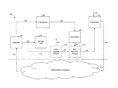
FIG. 1 illustrates an embodiment of a carbon dioxide reinjection process 100.
The
carbon dioxide reinjection process 100 may receive hydrocarbons and carbon
dioxide from a
subterranean hydrocarbon formation 114, separate heavy hydrocarbons and some
of the
NGLs from the carbon dioxide, and inject the carbon dioxide downhole. As shown
in FIG.
1, additional process steps may be included in the carbon dioxide reinjection
process, such
as compressing the carbon dioxide, dehydrating the carbon dioxide, and/or
adding additional
3
CA 02739366 2011-05-06
carbon dioxide to the carbon dioxide recycle stream. The specific steps in the
carbon
dioxide reinjection process 100 are explained in further detail below.
The carbon dioxide reinjection process 100 may receive a hydrocarbon feed
stream
152 from a subterranean hydrocarbon formation 114. The hydrocarbon feed stream
152
may be obtained from at least one recovery well as indicated by the upward
arrow in FIG. 1,
but also may be obtained from other types of wells. In addition, the
hydrocarbon feed
stream 152 may be obtained from the subterranean hydrocarbon formation 114
using any
suitable method. For example, if a suitable pressure differential exists
between the
subterranean hydrocarbon formation 114 and the surface, the hydrocarbon feed
stream 152
may flow to the surface via the pressure differential. Alternatively, surface
and/or downhole
pumps may be used to draw the hydrocarbon feed stream 152 from the
subterranean
hydrocarbon formation 114 to the surface.
Although the composition of the hydrocarbon feed stream 152 will vary from one
location to another, the hydrocarbon feed stream 152 may comprise carbon
dioxide,
methane, ethane, NGLs, heavy hydrocarbons, hydrogen sulfide (H2S), helium,
nitrogen,
water, or combinations thereof. The term "hydrocarbon" may refer to any
compound
comprising, consisting essentially of, or consisting of carbon and hydrogen
atoms. The term
"natural gas" may refer to any hydrocarbon that may exist in a gas phase under
atmospheric
or downhole conditions, and includes methane and ethane, but also may include
diminishing
amounts of C3 ¨ Cg hydrocarbons. The term "natural gas liquids" or NGLs may
refer to
natural gases that may be liquefied without refrigeration, and may include C3
¨ Cg
hydrocarbons. Both natural gas and NGL are terms known in the art and are used
herein as
such. In contrast, the term "heavy hydrocarbons" may refer to any hydrocarbon
that may
exist in a liquid phase under atmospheric or downhole conditions, and
generally includes
4
CA 02739366 2011-05-06
liquid crude oil, which may comprise C9+ hydrocarbons, branched hydrocarbons,
aromatic
hydrocarbons, and combinations thereof.
The hydrocarbon feed stream 152 may enter a separator 102. The separator 102
may
be any process equipment suitable for separating at least one inlet stream
into a plurality of
effluent streams having different compositions, states, temperatures, and/or
pressures. For
example, the separator 102 may be a column having trays, packing, or some
other type of
complex internal structure. Examples of such columns include scrubbers,
strippers,
absorbers, adsorbers, packed columns, and distillation columns having valve,
sieve, or other
types of trays. Such columns may employ weirs, downspouts, internal baffles,
temperature
control elements, and/or pressure control elements. Such columns also may
employ some
combination of reflux condensers and/or reboilers, including intermediate
stage condensers
and reboilers. Alternatively, the separator 102 may be a phase separator,
which is a vessel
that separates an inlet stream into a substantially vapor stream and a
substantially liquid
stream, such as a knock-out drum, flash drum, reboiler, condenser, or other
heat exchanger.
Such vessels also may have some internal baffles, temperature control
elements, and/or
pressure control elements, but generally lack any trays or other type of
complex internal
structure commonly found in columns. The separator 102 also may be any other
type of
separator, such as a membrane separator. In a specific embodiment, the
separator 102 is a
knockout drum. Finally, the separator 102 may be any combination of the
aforementioned
separators arranged in series, in parallel, or combinations thereof.
The separator 102 may produce a heavy hydrocarbon stream 154 and a carbon
dioxide recycle stream 156. The heavy hydrocarbon stream 154 may comprise most
of the
heavy hydrocarbons from the hydrocarbon feed stream 152. In embodiments, the
heavy
hydrocarbon stream 154 may comprise at least about 90 percent, at least about
95 percent, at
CA 02739366 2011-05-06
least about 99 percent, or substantially all of the heavy hydrocarbons from
the hydrocarbon
feed stream 152. The heavy hydrocarbon stream 154 may be sent to a pipeline
for
transportation or a storage tank 104, where it is stored until being
transported to another
location or being further processed. In contrast, the carbon dioxide recycle
stream 156 may
comprise most of the carbon dioxide from the hydrocarbon feed stream 152. In
embodiments, the carbon dioxide recycle stream 156 may comprise at least about
90
percent, at least about 95 percent, at least about 99 percent, or
substantially all of the carbon
dioxide from the hydrocarbon feed stream 152. Similarly, the carbon dioxide
recycle stream
156 may comprise at least about 80 percent, at least about 90 percent, at
least about 95
percent, or substantially all of the natural gas from the hydrocarbon feed
stream 152. All of
the percentages referred to herein are molar percentages until otherwise
specified.
The carbon dioxide recycle stream 156 may enter a compressor 106. The
compressor 106 may be any process equipment suitable for increasing the
pressure,
temperature, and/or density of an inlet stream. The compressor 106 may be
configured to
compress a substantially vapor phase inlet stream, a substantially liquid
phase inlet stream,
or combinations thereof. As such, the term "compressor" may include both
compressors
and pumps, which may be driven by electrical, mechanical, hydraulic, or
pneumatic means.
Specific examples of suitable compressors 106 include centrifugal, axial,
positive
displacement, turbine, rotary, and reciprocating compressors and pumps. In a
specific
embodiment, the compressor 106 is a turbine compressor. Finally, the
compressor 106 may
be any combination of the aforementioned compressors arranged in series, in
parallel, or
combinations thereof.
The compressor 106 may produce a compressed carbon dioxide recycle stream 158.
The compressed carbon dioxide recycle stream 158 may contain the same
composition as
6
CA 02739366 2011-05-06
the carbon dioxide recycle stream 156, but at a higher energy level. The
additional energy
in the compressed carbon dioxide recycle stream 158 may be obtained from
energy added to
the compressor 106, e.g., the electrical, mechanical, hydraulic, or pneumatic
energy. In
embodiments, difference in energy levels between the compressed carbon dioxide
recycle
stream 158 and the carbon dioxide recycle stream 156 is at least about 50
percent, at least
about 65 percent, or at least about 80 percent of the energy added to the
compressor 106.
The compressed carbon dioxide recycle stream 158 may enter a dehydrator 108.
The dehydrator 108 may remove some or substantially all of the water from the
compressed
carbon dioxide recycle stream 158. The dehydrator 108 may be any suitable
dehydrator,
such as a condenser, an absorber, or an adsorber. Specific examples of
suitable dehydrators
108 include refrigerators, molecular sieves, liquid desiccants such as glycol,
solid desiccants
such as silica gel or calcium chloride, and combinations thereof. The
dehydrator 108 also
may be any combination of the aforementioned dehydrators arranged in series,
in parallel, or
combinations thereof. In a specific embodiment, the dehydrator 108 is a glycol
unit. Any
water accumulated within or exiting from the dehydrator 108 may be stored,
used for other
processes, or discarded.
The dehydrator 108 may produce a dehydrated carbon dioxide recycle stream 160.
The dehydrated carbon dioxide recycle stream 160 may contain little water,
e.g., liquid
water or water vapor. In embodiments, the dehydrated carbon dioxide recycle
stream 160
may comprise no more than about 5 percent, no more than about 3 percent, no
more than
about 1 percent, or be substantially free of water.
The dehydrated carbon dioxide recycle stream 160 may enter a NGL recovery
process 110. The NGL recovery process 110 may separate the dehydrated carbon
dioxide
recycle stream 160 into a NGL rich stream 162 and a purified carbon dioxide
recycle stream
7
CA 02739366 2011-05-06
164. The NGL rich stream 162 may only comprise a portion of the total NGLs
from the
dehydrated carbon dioxide recycle stream 160. For example, the NGL rich stream
162 may
comprise less than about 70 percent, from about 10 percent to about 50
percent, or from
about 20 percent to about 35 percent of the NGLs from the dehydrated carbon
dioxide
recycle stream 160. By taking a less aggressive cut of the NGLs and/or
disregarding the
recovery of methane, ethane, and optionally propane from the dehydrated carbon
dioxide
recycle stream 160, the NGL recovery process 110 may produce a relatively high
quality
NGL rich stream 162 with relatively little process equipment or energy. A
specific example
of a suitable NGL recovery process 110 is shown in FIG. 2 and described in
further detail
below.
As mentioned above, the NGL recovery process 110 may produce a relatively high-
quality NGL rich stream 162. Specifically, while the NGL recovery process 110
recovers
only a portion, e.g., about 20 to about 35 percent, of the NGLs in the
dehydrated carbon
dioxide recycle stream 160, the resulting NGL rich stream 162 is relatively
lean with respect
to methane and the acid gases. For example, the NGL rich stream 162 may
comprise most
of the butane and heavier components from the dehydrated carbon dioxide
recycle stream
160. For example, the NGL rich stream 162 may comprise at least about 90
percent, at least
about 95 percent, at least about 99 percent, or substantially all of the C4+
from the
dehydrated carbon dioxide recycle stream 160. In an embodiment, the NGL rich
stream 162
may comprise at least about 20 percent, at least about 40 percent, at least
about 60 percent,
or at least about 70 percent of the C3+ from the dehydrated carbon dioxide
recycle stream
160. In embodiments, the NGL rich stream 162 may comprise no more than about
10
percent, no more than about 5 percent, no more than about 1 percent, or be
substantially free
of ethane. Similarly, the NGL rich stream 162 may comprise no more than about
5 percent,
8
CA 02739366 2011-05-06
no more than about 3 percent, no more than about 1 percent, or be
substantially free of
methane. Moreover, the NGL rich stream 162 may comprise no more than about 5
percent,
no more than about 3 percent, no more than about 1 percent, or be
substantially free of acid
gases, such as carbon dioxide or hydrogen sulfide. It will be realized that
the composition of
the NGL rich stream 162 may be dependent on the dehydrated carbon dioxide
recycle
stream 160 composition. The examples provided below show the composition of
the NGL
rich stream 162 for three different dehydrated carbon dioxide recycle stream
160
compositions. The NGL rich stream 162 may be sent to a pipeline for
transportation or a
storage tank, where it is stored until being transported to another location
or being further
processed.
In an embodiment, the NGL rich stream 162 optionally may be processed in an
NGL
upgrade process 170. The NGL upgrade process 170 may produce a relatively
heavy NGL
stream 172 that may be combined with the heavy hydrocarbon stream 154. When
combined, the heavy NGL stream 172 and the heavy hydrocarbon stream 154 may
meet or
exceed the pipeline and/or transportation thresholds or standards for a heavy
hydrocarbon
stream, as described in more detail with respect to Figure 4. A relatively
light NGL stream
174 may be sent to a pipeline for transportation or a storage tank, where it
may be stored
until transported to another location or further processed, as described in
more detail with
respect to Figure 4. A specific example of a suitable NGL upgrade process 170
is shown in
FIG. 5 and described in further detail below.
As mentioned above, the NGL recovery process 110 may produce a purified carbon
dioxide recycle stream 164. The purified carbon dioxide recycle stream 164 may
comprise
most of the carbon dioxide from the dehydrated carbon dioxide recycle stream
160, as well
as some other components such as methane, ethane, propane, butane, nitrogen,
and
9
CA 02739366 2011-05-06
hydrogen sulfide. In embodiments, the purified carbon dioxide recycle stream
164 may
comprise at least about 90 percent, at least about 95 percent, at least about
99 percent, or
substantially all of the carbon dioxide from the dehydrated carbon dioxide
recycle stream
160. In addition, the purified carbon dioxide recycle stream 164 may comprise
at least about
90 percent, at least about 95 percent, at least about 99 percent, or
substantially all of the
methane from the dehydrated carbon dioxide recycle stream 160. As such, the
purified
carbon dioxide recycle stream 164 may comprise at least about 65 percent, at
least about 80
percent, at least about 90 percent, or at least about 95 percent carbon
dioxide. In
embodiments, the purified carbon dioxide recycle stream 164 may comprise no
more than
about 10 percent, no more than about 5 percent, no more than about 1 percent,
or be
substantially free of C3+. Similarly, the purified carbon dioxide recycle
stream 164 may
comprise no more than about 20 percent, no more than about 10 percent, no more
than about
percent, or be substantially free of C2+.
The purified carbon dioxide recycle stream 164 may enter a compressor 112. The
compressor 112 may comprise one or more compressors, such as the compressor
106
described above. In a specific embodiment, the compressor 112 is a turbine
compressor.
The compressor 112 may compress the purified carbon dioxide recycle stream
164, thereby
producing a carbon dioxide injection stream 168. The carbon dioxide injection
stream 168
may contain the same composition as the purified carbon dioxide recycle stream
164, but at
a higher energy level. The additional energy in the carbon dioxide injection
stream 168 may
be obtained from energy added to the compressor 112, e.g., the electrical,
mechanical,
hydraulic, or pneumatic energy. In some embodiments, the difference in energy
levels
between the carbon dioxide injection stream 168 and the purified carbon
dioxide recycle
CA 02739366 2011-05-06
stream 164 is at least about 50 percent, at least about 65 percent, or at
least about 80 percent
of the energy added to the compressor 112.
In some embodiments, a makeup stream 166 may be combined with either the
purified carbon dioxide recycle stream 164 or the carbon dioxide injection
stream 168.
Specifically, as the carbon dioxide reinjection process 100 is operated,
carbon dioxide and
other compounds will be lost, e.g., by replacing the hydrocarbons in the
subterranean
hydrocarbon formation 114, by leakage into inaccessible parts of the
subterranean
hydrocarbon formation 114, and/or to other causes. Alternatively, it may be
desirable to
increase the amount of carbon dioxide and other compounds injected downhole.
As such,
the makeup stream 166 may be combined with either the purified carbon dioxide
recycle
stream 164 and/or the carbon dioxide injection stream 168, for example in the
compressor
112. Alternatively or additionally, the makeup stream 166 may be combined with
the
carbon dioxide recycle stream 156, the compressed carbon dioxide recycle
stream 158, the
dehydrated carbon dioxide recycle stream 160, or combinations thereof. The
makeup stream
166 may comprise carbon dioxide, nitrogen, methane, ethane, air, water, or any
other
suitable compound. In an embodiment, the makeup stream 166 comprises at least
75
percent, at least 85 percent, or at least 95 percent carbon dioxide, nitrogen,
methane, air,
water, or combinations thereof. Finally, the carbon dioxide injection stream
168 may be
sent to a carbon dioxide pipeline rather than being immediately injected
downhole. In such
a case, the carbon dioxide injection stream 168 may meet the carbon dioxide
pipeline
specifications. One example of a carbon dioxide pipeline specification is: at
least about 95
percent carbon dioxide, substantially free of free water, no more than about
30 pounds of
vapor-phase water per million cubic feet (mmcf) of product, no more than about
20 parts per
million (ppm) by weight of hydrogen sulfide, no more than about 35 ppm by
weight of total
11
CA 02739366 2011-05-06
sulfur, a temperature of no more than about 120 F, no more than about four
percent
nitrogen, no more than about five percent hydrocarbons (wherein the
hydrocarbons do not
have a dew point exceeding about -20 F), no more than about 10 ppm by weight
of oxygen,
and more than about 0.3 gallons of glycol per mmcf of product (wherein the
glycol is not in
the liquid state at the pressure and temperature conditions of the pipeline).
FIG. 2 illustrates an embodiment of a NGL recovery process 200. The NGL
recovery process 200 may recover some of the NGLs from a carbon dioxide
recycle stream
described above. For example, the NGL recovery process 200 may be implemented
as part
of the carbon dioxide reinjection process 100, e.g., by separating the
dehydrated carbon
dioxide recycle stream 160 into a NGL rich stream 162 and a purified carbon
dioxide
recycle stream 164. Alternatively, the NGL recovery process 200 may be
implemented as a
stand-alone process for recovering NGLs from a hydrocarbon containing stream.
The NGL recovery process 200 may begin by cooling the dehydrated carbon
dioxide
recycle stream 160 in a heat exchanger 202. The heat exchanger 202 may be any
equipment
suitable for heating or cooling one stream using another stream. Generally,
the heat
exchanger 202 is a relatively simple device that allows heat to be exchanged
between two
fluids without the fluids directly contacting each other. Examples of suitable
heat
exchangers 202 include shell and tube heat exchangers, double pipe heat
exchangers, plate
fin heat exchangers, bayonet heat exchangers, reboilers, condensers,
evaporators, and air
coolers. In the case of air coolers, one of the fluids comprises atmospheric
air, which may
be forced over tubes or coils using one or more fans. In a specific
embodiment, the heat
exchanger 202 is a shell and tube heat exchanger.
As shown in FIG. 2, the dehydrated carbon dioxide recycle stream 160 may be
cooled using the cooled, purified carbon dioxide recycle stream 258.
Specifically, the
12
CA 02739366 2011-05-06
dehydrated carbon dioxide recycle stream 160 is cooled to produce the cooled
carbon
dioxide recycle stream 252, and the cooled, purified carbon dioxide recycle
stream 258 is
heated to produce the purified carbon dioxide recycle stream 164. The
efficiency of the heat
exchange process depends on several factors, including the heat exchanger
design, the
temperature, composition, and flowrate of the hot and cold streams, and/or the
amount of
thermal energy lost in the heat exchange process. In embodiments, the
difference in energy
levels between the dehydrated carbon dioxide recycle stream 160 and the cooled
carbon
dioxide recycle stream 252 is at least about 60 percent, at least about 70
percent, at least
about 80, or at least about 90 percent of the difference in energy levels
between the cooled,
purified carbon dioxide recycle stream 258 and the purified carbon dioxide
recycle stream
164.
The cooled carbon dioxide recycle stream 252 then enters a NGL stabilizer 204.
The
NGL stabilizer 204 may comprise a separator 206, a condenser 208, and a
reboiler 210. The
separator 206 may be similar to any of the separators described herein, such
as separator
102. In a specific embodiment, the separator 206 is a distillation column. The
condenser
208 may receive an overhead 254 from the separator 206 and produce the cooled,
purified
carbon dioxide recycle stream 258 and a reflux stream 256, which is returned
to the
separator 206. The condenser 208 may be similar to any of the heat exchangers
described
herein, such as heat exchanger 202. In a specific embodiment, the condenser
208 is a shell
and tube, kettle type condenser coupled to a refrigeration process, and
contains a reflux
accumulator. As such, the condenser 208 may remove some energy 282 from the
reflux
stream 256 and cooled, purified carbon dioxide recycle stream 258, typically
by
refrigeration. The cooled, purified carbon dioxide recycle stream 258 is
substantially similar
in composition to the purified carbon dioxide recycle stream 164 described
above.
13
CA 02739366 2011-05-06
Similarly, the reboiler 210 may receive a bottoms stream 260 from the
separator 206 and
produce a sour NGL rich stream 264 and a boil-up stream 262, which is returned
to the
separator 206. The reboiler 210 may be like any of the heat exchangers
described herein,
such as heat exchanger 202. In a specific embodiment, the reboiler 210 is a
shell and tube
heat exchanger coupled to a hot oil heater. As such, the reboiler 210 adds
some energy 284
to the boil-up stream 262 and the sour NGL rich stream 264, typically by
heating. The sour
NGL rich stream 264 may be substantially similar in composition to the NGL
rich stream
162, with the exception that the sour NGL rich stream 264 has some additional
acid gases,
e.g., acid gases 270 described below.
The sour NGL rich stream 264 then may be cooled in another heat exchanger 212.
The heat exchanger 212 may be like any of the heat exchangers described
herein, such as
heat exchanger 202. For example, the heat exchanger 212 may be an air cooler
as described
above. A cooled, sour NGL rich stream 266 may exit the heat exchanger 212 and
enter a
throttling valve 214. The throttling valve 214 may be an actual valve such as
a gate valve,
globe valve, angle valve, ball valve, butterfly valve, needle valve, or any
other suitable
valve, or may be a restriction in the piping such as an orifice or a pipe
coil, bend, or size
reduction. The throttling valve 214 may reduce the pressure, temperature, or
both of the
cooled, sour NGL rich stream 266 and produce a low-pressure sour NGL rich
stream 268.
The cooled, sour NGL rich stream 266 and the low-pressure sour NGL rich stream
268 have
substantially the same composition as the sour NGL rich stream 264, albeit
with lower
energy levels.
The low-pressure sour NGL rich stream 268 then may be sweetened in a separator
216. The separator 216 may be similar to any of the separators described
herein, such as
separators 102 or 206. In an embodiment, the separator 216 may be one or more
packed
14
CA 02739366 2011-05-06
columns that use a sweetening process to remove acid gases from the low-
pressure sour
NGL rich stream 268. Suitable sweetening processes include amine solutions,
physical
solvents such as SELEXOL or RECTISOL, mixed amine solution and physical
solvents,
potassium carbonate solutions, direct oxidation, absorption, adsorption using,
e.g., molecular
sieves, or membrane filtration. The separator 216 may produce the NGL rich
stream 162
described above. In addition, any acid gases 270 accumulated within or exiting
from the
separator 216 may be stored, used for other processes, or suitably disposed
of. Finally,
while FIGS. 1 and 2 are described in the context of carbon dioxide
reinjection, it will be
appreciated that the concepts described herein can be applied to other
reinjection processes,
for example those using nitrogen, air, or water.
FIG. 3 illustrates an embodiment of a chart 300 depicting the relationship
between
the NGL recovery rate and the energy expended to recover NGLs in the NGL
recovery
process. The NGL recovery rate may be a percentage recovery, and may represent
the
amount of C3+ in the carbon dioxide recycle stream that is recovered in the
NGL rich stream.
The energy requirement may be measured in joules (J) or in horsepower (hp),
and may
represent the energy required to generate the condenser energy and reboiler
energy
described above. If additional compressors are needed at any point in the
carbon dioxide
reinjection process than would be required in an otherwise similar carbon
dioxide reinjection
process that lacks the NGL recovery process, then the energy required to
operate such
compressors may be included in the energy requirement shown in FIG. 3.
As shown by curve 302, the energy requirements may increase about
exponentially
as the NGLs are recovered at higher rates. In other words, substantially
higher energy may
be required to recover the NGLs at incrementally higher rates. For example,
recovering a
first amount 304 of from about 20 percent to about 35 percent of C3+ may
require
CA 02739366 2011-05-06
substantially less energy than recovering a second amount 306 of from about 40
percent to
about 65 percent of C3+. Moreover, recovering the second amount 306 of from
about 40
percent to about 65 percent of C3+ may require substantially less energy than
recovering a
third amount 308 of from about 70 percent to about 90 percent of C3+. Such
significant
reduction in energy requirements may be advantageous in terms of process
feasibility and
cost, where relatively small decreases in NGL recovery rates may require
significantly less
energy and process equipment, yielding significantly better process economics.
Although
the exact relationship of the curve 302 may depend on numerous factors
especially the price
of C3+, in an embodiment the economics of the NGL recovery process when the
NGL
recovery rate is in the second amount 306 may be better than the economics of
the NGL
recovery process when the NGL recovery rate is in the third amount 308.
Similarly, the
economics of the NGL recovery process when the NGL recovery rate is in the
first amount
304 may be significantly better than the economics of the NGL recovery process
when the
NGL recovery rate is in the second amount 306. Such a relationship is
counterintuitive
considering that in many other processes, the process economics generally
improve with
increased recovery rates.
FIG. 4 illustrates an embodiment of a NGL upgrade process 500. The NGL upgrade
process 500 may separate a portion of the heavier components of the NGL rich
stream 162
for blending with the heavy hydrocarbon stream 154. For example, the NGL
upgrade
process 500 may be used to produce a relatively heavy NGL stream 172 for
combining with
the heavy hydrocarbon stream 154 and a relatively light NGL stream 174 that
may be sold
and/or used as a NGL product. In general, the heavy hydrocarbon stream 154 may
sell for a
higher price than the NGL rich stream 162. By mixing at least a portion of the
NGL rich
stream 162 with the heavy hydrocarbon stream 154, the NGL upgrade process 500
may be
16
CA 02739366 2011-05-06
used to improve the economics and/or revenue from the NGL recovery process. As
a result,
the NGL upgrade process 500 may be considered in the NGL recovery optimization
method
400 described in more detail below.
The NGL upgrade process 500 may begin by passing the NGL rich stream 162 into
an NGL upgrade unit 502. The NGL rich stream 162 may be in the liquid phase
after
passing through separator 216. The NGL upgrade unit 502 may comprise a
separator 506,
and a reboiler 510. While not illustrated in FIG. 4, some embodiments of the
NGL upgrade
unit 502 also may comprise a condenser. The separator 506 may be similar to
any of the
separators described herein, such as separator 102. In a specific embodiment,
the separator
506 is a stripping column with a partial reboiler 510, and the separator 506
may not
comprise a condenser. The downcoming liquid phase may be provided by the
liquid NGL
rich stream 162, which may be introduced at or near the top of the separator
506. In an
embodiment, a condenser may be used to at least partially condense overhead
stream 524 to
produce at least a portion of the downcoming liquid in separator 506. For
example, the
condenser may be similar to any of the heat exchangers described herein, such
as heat
exchanger 202. The reboiler 510 may receive a bottoms stream 508 from the
separator 506
and produce a heavy NGL stream 514 and a boil-up stream 512, which is returned
to the
separator 506 to provide the rising vapor phase within the separator 506. The
reboiler 510
may be like any of the heat exchangers described herein, such as heat
exchanger 202. In a
specific embodiment, the reboiler 510 is a shell and tube heat exchanger
coupled to a hot oil
heater. As such, the reboiler 510 adds some energy 516 to the boil-up stream
512 and the
heavy NGL stream 514, typically by heating. The heavy NGL stream 514 may be
substantially similar in composition to the heavy NGL stream 172.
17
CA 02739366 2011-05-06
The heavy NGL stream 514 then may be cooled in a heat exchanger 518. The heat
exchanger 518 may be any equipment suitable for heating or cooling one stream
using
another stream. Generally, the heat exchanger 518 is a relatively simple
device that allows
heat to be exchanged between two fluids without the fluids directly contacting
each other
(i.e., indirect heat exchange). In an embodiment, heat integration that
comprises using one
or more streams in the overall process to cool the heavy NGL stream 514, and
thereby
heating the one or more streams, may be used with heat exchanger 518. Examples
of
suitable heat exchangers 518 include shell and tube heat exchangers, double
pipe heat
exchangers, plate fin heat exchangers, bayonet heat exchangers, reboilers,
condensers,
evaporators, and air coolers. In the case of air coolers, one of the fluids
comprise
atmospheric air, which may be forced over tubes or coils using one or more
fans. In a
specific embodiment, the heat exchanger 518 is a shell and tube heat exchanger
with the
heavy NGL stream 514 passing on one side of the exchanger and a cooling fluid
stream 522
passing on the other. The cooled, heavy NGL stream 172 may have substantially
the same
composition as the heavy NGL stream 514, albeit with lower energy levels.
The overhead stream 524 from separator 506 may comprise at least a portion of
the
lighter NGL components and may be cooled in another heat exchanger 526. The
heat
exchanger 526 may be like any of the heat exchangers described herein, such as
heat
exchanger 202. For example, the heat exchanger 526 may be an air cooler as
described
above. The cooled, light NGL stream 174 may have substantially the same
composition as
the overhead stream 524, albeit with lower energy levels.
As shown in FIG. 4, one or more additional NGL input streams 530, 532 may be
introduced into the NGL upgrade process 500 upstream of the NGL upgrade unit
502. The
additional NGL input streams 530, 532 may comprise NGL streams from any
suitable
18
CA 02739366 2011-05-06
source, such as one or more additional recovery plants. The NGL input streams
530, 532
may be transported to the NGL upgrade unit 502 by any suitable means. For
example, the
NGL input streams 530, 532 may be transported to the NGL upgrade unit 502
through a
pipeline or by truck. The additional NGL input streams 530, 532 may contain
one or more
acid gases and/or other contaminants. Depending on their compositions, the
additional NGL
input streams 530, 532 may be introduced at various input locations in the NGL
recovery
process. For example, an input location may comprise a point upstream of the
separator 216
for an NGL input stream 530 comprising acid gas components at or above a
threshold level
(e.g., a pipeline or storage threshold), thereby allowing for sweetening prior
to being
introduced to the downstream processes. As another example, an input location
for an NGL
input stream 532 that comprises acid gas components below the threshold level
may
comprise a point downstream of the separator 216, thereby reducing the energy
use of the
overall recovery process. The use of one or more additional input streams may
allow an
NGL upgrade process 500 to upgrade the NGL streams from a plurality of NGL
recovery
processes. For example, multiple NGL recovery processes and/or additional
sources of =
NGL rich streams may feed the NGL product to a NGL upgrade process, thereby
reducing
the need to install an NGL upgrade process at each source of an NGL stream.
In general, the NGL upgrade process may be used to separate a relatively heavy
NGL stream 172 for blending with the heavy hydrocarbon stream 154. The
composition
and flowrate of the heavy NGL stream 172 may vary depending on the composition
and
flowrate of the heavy hydrocarbon stream 154. As discussed above, the heavy
hydrocarbon
stream 154 may be sent to a pipeline for transportation or a storage tank,
where it is stored
until being transported to another location or being further processed. Each
of the
downstream uses for the heavy hydrocarbon stream 154 may have one or more
thresholds
19
CA 02739366 2011-05-06
and/or standards that the heavy hydrocarbon stream 154 must meet in order to
be transported
or further processed. For example, pipelines may generally have standards
setting
thresholds for fluids passing through the pipeline, such as thresholds on
vapor pressure (e.g.,
expressed as a Reid vapor pressure standard), carbon dioxide content, acid gas
content (e.g.,
hydrogen sulfide content), and water content (e.g., a dew point standard). In
an
embodiment, the fluid transported in the pipeline may have a Reid vapor
pressure of no
more than about 20, no more than about 15, or no more than about 10.
Accordingly, the
composition and the flowrate of the heavy NGL stream 172 may be controlled so
that the
heavy hydrocarbon stream 154 may meet the transportation and/or further
processing
standards and/or threshold downstream of the mixing point between the heavy
hydrocarbon
stream 154 and the heavy NGL stream 172.
In an embodiment, the composition and/or flowrate of the heavy NGL stream 172
and the light NGL stream 174 may be controlled, at least in part, to allow the
light NGL
stream 174 to satisfy one or more transportation thresholds. The light NGL
stream 174 may
be transported using a variety of transportation means and/or methods
including, but not
limited to, a pipeline and a tanker truck. Each transportation method may have
one or more
thresholds that the light NGL stream 174 may need to satisfy prior to being
accepted for
transportation. For example, a pipeline may have a heating value standard of
between about
1,000 British thermal units per cubic foot (Btu/ft3) and about 1,200 Btude, or
alternatively
between about 1,050 Btudt3 and about 1,100 Btu/ft3. In an embodiment, the
light NGL
stream 174 also may be subject to a dew point standard. As another example,
tanker truck
transportation may have a vapor pressure requirement that the light NGL stream
174 not
exceed a vapor pressure of about 250 pounds per square inch gauge (psig) at a
temperature
of 100 F. Based on the applicable thresholds, the composition and the
flowrate of the
CA 02739366 2011-05-06
heavy NGL stream 172 and the light NGL stream 174 may be controlled so that
the light
NGL stream 174 may meet the transportation thresholds, allowing the light NGL
stream 174
to be transported for further use.
FIG. 5 illustrates another embodiment of a carbon dioxide reinjection process
600.
The process shown in FIG. 5 and the process of FIG. 1 are similar, and those
portions with
similar numbering are described in more detail with respect to FIG. 1 above.
In the interest
of brevity, only those portions that differ from FIG. 1 will be discussed with
respect to FIG.
5.
As can be seen in FIG. 5, the dehydration of the compressed carbon dioxide
recycle
stream 158 may be integrated with the NGL recovery/dehydration process 610.
The
compressed carbon dioxide recycle stream 158 may enter a NGL
recovery/dehydration
process 610. In an embodiment, the NGL recovery/dehydration process 610 may
comprise
a separator 102 that produces multiple streams and allow one or more phases of
the
compressed carbon dioxide recycle stream 158 to be dehydrated without
dehydrating the
entirety of the compressed carbon dioxide recycle stream 158. This may allow
for a
reduction in the size of the dehydration unit and a reduction in the operating
expense
associated with the dehydrator. Further, the separate processing of the phases
may allow the
downstream processing units to receive each phase at a different location,
which may further
improve the process economics as described in more detail below with respect
to FIG. 7.
The compressed carbon dioxide recycle stream 158 may enter the NGL
recovery/dehydration process 610. The NGL recovery/dehydration process 610 may
dehydrate, process, and separate the compressed carbon dioxide recycle stream
158 into a
NGL rich stream 162 and a purified carbon dioxide recycle stream 164. The NGL
rich
stream 162 may only comprise a portion of the total NGLs from the dehydrated
carbon
21
CA 02739366 2011-05-06
dioxide recycle stream 160. A specific example of a suitable NGL
recovery/dehydration
process 610 is shown in FIG. 6 and described in further detail below.
As mentioned above, the NGL recovery/dehydration process 610 may produce a
relatively high-quality NGL rich stream 162. The NGL rich stream 162 may have
about the
same composition as the NGL rich stream 162 in FIG. 1. The NGL rich stream 162
may be
sent to a pipeline for transportation or a storage tank, where it is stored
until transported to
another location or further processed. In an embodiment, the NGL rich stream
optionally
may be processed in an NGL upgrade process 170, as described in more detail
above. The
NGL upgrade process 170 may produce a relatively heavy NGL stream 172 that may
be
combined with the heavy hydrocarbon stream 154. When combined, the heavy NGL
stream
172 and the heavy hydrocarbon stream 154 may meet or exceed the pipeline
and/or
transportation properties for a heavy hydrocarbon stream. A relatively light
NGL stream
174 may be sent to a pipeline for transportation or a storage tank 104, where
it may be stored
until being transported to another location or being further processed. A
specific example of
a suitable NGL upgrade process 170 is shown in FIG. 4 and described in further
detail
above.
As mentioned above, the NGL recovery/dehydration process 610 may produce a
purified carbon dioxide recycle stream 164. The purified carbon dioxide
recycle stream 164
may have about the same composition as the purified carbon dioxide recycle
stream 164 in
FIG. 1. The purified carbon dioxide recycle stream 164 may enter a compressor
112. The
compressor 112 may comprise one or more compressors, such as the compressor
106
described above. In some embodiments, a makeup stream 166 may be combined with
either
the purified carbon dioxide recycle stream 164 or the carbon dioxide injection
stream 168.
22
CA 02739366 2011-05-06
The resulting carbon dioxide injection stream 168 then may be injected into
the subterranean
hydrocarbon formation 114 or sent to a carbon dioxide pipeline.
FIG. 6 illustrates an embodiment of a NGL recovery/dehydration process 700.
The
NGL recovery/dehydration process 700 may dehydrate and recover some of the
NGLs from
a carbon dioxide recycle stream. For example, the NGL recovery/dehydration
process 700
may be implemented as part of the carbon dioxide reinjection process 600,
e.g., by
separating the dehydrated carbon dioxide recycle stream 160 into a NGL rich
stream 162
and a purified carbon dioxide recycle stream 164.
The NGL recovery process 700 may begin by cooling the compressed carbon
dioxide recycle stream 158 in a heat exchanger 702. The heat exchanger 702 may
be any
equipment suitable for heating or cooling one stream using another stream.
Generally, the
heat exchanger 702 is a relatively simple device that allows heat to be
exchanged between
two fluids without the fluids directly contacting each other. Examples of
suitable heat
exchangers 702 include shell and tube heat exchangers, double pipe heat
exchangers, plate .
fin heat exchangers, bayonet heat exchangers, reboilers, condensers,
evaporators, and air
coolers. In the case of air coolers, one of the fluids comprises atmospheric
air, which may
be forced over tubes or coils using one or more fans. In a specific
embodiment, the heat
exchanger 702 is a shell and tube heat exchanger.
As shown in FIG. 6, the compressed carbon dioxide recycle stream 158 may be
cooled using the cooled, purified carbon dioxide recycle stream 758.
Specifically, the
compressed carbon dioxide recycle stream 158 is cooled to produce the cooled
carbon
dioxide recycle stream 752, and the cooled, purified carbon dioxide recycle
stream 758 is
heated to produce the purified carbon dioxide recycle stream 164. The
efficiency of the heat
exchange process depends on several factors, including the heat exchanger
design, the
23
i
CA 02739366 2011-05-06
temperature, composition, and flowrate of the hot and cold streams, and/or the
amount of
thermal energy lost in the heat exchange process. In embodiments, the
difference in energy
levels between the compressed carbon dioxide recycle stream 158 and the cooled
carbon
dioxide recycle stream 752 is at least about 60 percent, at least about 70
percent, at least
about 80, or at least about 90 percent of the difference in energy levels
between the cooled,
purified carbon dioxide recycle stream 758 and the purified carbon dioxide
recycle stream
164.
The cooled carbon dioxide recycle stream 752 then enters a separator 718. The
separator 718 may be similar to any of the separators described herein, such
as separator
102. In a specific embodiment, the separator 718 is a three phase separator,
which is a
vessel that separates an inlet stream into three distinct phases such as a
substantially vapor
stream, a substantially first liquid stream (e.g., an organic liquid phase),
and a substantially
second liquid stream (e.g., an aqueous liquid phase). The first liquid stream
may primarily
comprise hydrocarbons and the second liquid stream may primarily comprise an
aqueous
fluid so that the first and second liquid streams are at least partially
insoluble in each other
and form two separable liquid phases. A three-phase separator may have some
internal
baffles and/or weirs, temperature control elements, and/or pressure control
elements, but
generally lacks any trays or other type of complex internal structure commonly
found in
columns. In an embodiment, the separator 718 may separate the cooled carbon
dioxide
recycle stream 752 into a vapor recycle stream 724, a liquid recycle stream
728, and an
aqueous fluid stream 732. The aqueous fluid stream 732 exiting from the
dehydrator 722
may be stored, used for other processes, or discarded. The aqueous fluid
stream 732 may
first be treated to remove a portion of any hydrocarbons in the stream prior
to storage,
further use or process, or being discarded.
24
CA 02739366 2011-05-06
The vapor recycle stream 724 optionally may enter a dehydrator 720. The
dehydrator 720 may remove some or substantially all of the water from the
vapor recycle
stream 724. The dehydrator 720 may be any suitable dehydrator, such as a
condenser, an
absorber, or an adsorber.
Specific examples of suitable dehydrators 720 include
refrigerators, molecular sieves, liquid desiccants such as glycol, solid
desiccants such as
silica gel or calcium chloride, and combinations thereof. The dehydrator 720
also may be
any combination of the aforementioned dehydrators 720 and 722 arranged in
series, in
parallel, or combinations thereof In a specific embodiment, the dehydrator 720
is a glycol
unit. Any water accumulated within or exiting from the dehydrator 720 may be
stored, used
for other processes, or discarded.
The dehydrator 720 may produce a dehydrated vapor recycle stream 726. The
dehydrated vapor recycle stream 726 may contain little water, e.g., liquid
water or water
vapor. In embodiments, the dehydrated vapor recycle stream 726 may comprise no
more
than about 5 percent, no more than about 3 percent, no more than about 1
percent, or be
substantially free of water.
The liquid recycle stream 728 from the separator 718 optionally may enter a
dehydrator 722. The dehydrator 722 may remove some or substantially all of the
water from
the liquid recycle stream 728. The dehydrator 722 may be any suitable
dehydrator, such as a
condenser, an absorber, or an adsorber. Suitable liquid-liquid separators such
as hydro-
cyclones and heater treaters also may be used. In an embodiment, the water in
the liquid
recycle stream 728 may be in the form of hydrates (e.g., clathrate hydrates)
and/or an
emulsion. Suitable separators utilizing physical solvents, chemical solvents,
and or heat
may be used to break the hydrates and/or emulsion and separate the water from
the
remaining liquid recycle stream 728 components. Specific examples of suitable
dehydrators
CA 02739366 2011-05-06
722 include hydro-cyclones, heater treaters, molecular sieves, liquid
desiccants such as
glycol, solid desiccants such as silica gel or calcium chloride, and
combinations thereof.
The dehydrator 722 also may be any combination of the aforementioned
dehydrators 722
arranged in series, in parallel, or combinations thereof. Any water
accumulated within or
exiting from the dehydrator 722 may be stored, used for other processes, or
discarded.
The dehydrator 722 may produce a dehydrated liquid recycle stream 730. The
dehydrated liquid recycle stream 730 may contain little water, e.g., liquid
water or water
vapor. In embodiments, the dehydrated liquid recycle stream 730 may comprise
no more
than about 5 percent, no more than about 3 percent, no more than about 1
percent, or be
substantially free of water.
In an embodiment, only one of the dehydrators 720, 722 may be used. For
example,
any water contained in the cooled carbon dioxide recycle stream 752 may
preferentially
distribute to the vapor recycle stream 724 or the liquid recycle stream 728.
By only using
one separator 720, 722 on the stream containing the majority of the water, the
dehydration
requirements may be reduced, thereby reducing both the installation and
operating costs
associated with operating the dehydration system. In an embodiment in which
only one
dehydrator is used, the remaining stream may pass directly from the separator
718 to the
separator 706. In an embodiment, both dehydrators 720, 722 may be used, and
dehydrators
720, 722 may comprise different types of dehydrators. For example, dehydrator
720 may
comprise a gas dehydration system while dehydrator 722 may comprise a unit
designed to
primarily perform a liquid-liquid phase separation. In an embodiment, both
dehydrators
720, 722 may be used and the separator 718 may be used to perform a first
stage separation
of any free water, thereby reducing the dehydration requirements. In still
another
embodiment, neither dehydrator 720, 722 may be used and rather separator 718
may be
26
CA 02739366 2011-05-06
sufficient for removing any free water and thereby dehydrating the cooled
carbon dioxide
recycle stream 752 along with performing a first stage flash of the cooled
carbon dioxide
recycle stream 752 to allow the stream to be introduced to the NGL
fractionator 704 as
separate streams. In yet another embodiment, the vapor recycle stream 724 and
the liquid
recycle stream 728 may be combined and passed to a single dehydrator.
The dehydrated vapor recycle stream 726 and the dehydrated liquid recycle
stream
730 then may enter a NGL fractionator 704 as separate streams. In an
embodiment, the
dehydrated vapor recycle stream 726 and the dehydrated liquid recycle stream
730 may be
fed to a separator 706 in the NGL fractionator 704 at separate input
locations. The ability to
feed the dehydrated vapor recycle stream 726 and the dehydrated liquid recycle
stream 730
at separate locations in the separator 706 may aid in the separation of the
various
components into the overhead stream 754 and the bottoms stream 760. While the
dehydrated vapor recycle stream 726 is illustrated as entering the separator
706 above the
dehydrated liquid recycle stream 730, the dehydrated vapor recycle stream 726
may entering
the separator 706 below the dehydrated liquid recycle stream 730, or enter at
or near the
same tray and/or location. In an embodiment, the dehydrated vapor recycle
stream 726 and
the dehydrated liquid recycle stream 730 may be combined prior to entering the
NGL
fractionator 704.
The NGL fractionator 704 may comprise a separator 706, a condenser 708, and a
reboiler 710. The separator 706 may be similar to any of the separators
described herein,
such as separator 102. In a specific embodiment, the separator 706 is a
distillation column.
In an embodiment, dehydrated vapor recycle stream 726 may be introduced onto
the tray
and/or inlet location (e.g., when structured packing is used) with the closest
matching vapor
composition in the distillation column. Similarly, the dehydrated liquid
recycle stream 730
27
CA 02739366 2011-05-06
may be introduced onto the tray and/or inlet location with the closest
matching liquid
composition. Actual compositional measurements and/or process models may be
used to
match the dehydrated vapor recycle stream 726 and the dehydrated liquid
recycle stream
730 to the appropriate trays and/or inlet location in the distillation column.
The condenser 708 may receive an overhead stream 754 from the separator 706
and
produce the cooled, purified carbon dioxide recycle stream 758 and a reflux
stream 756,
which is returned to the separator 706. The condenser 708 may be similar to
any of the heat
exchangers described herein, such as heat exchanger 702. In a specific
embodiment, the
condenser 708 is a shell and tube, kettle type condenser coupled to a
refrigeration process,
and contains a reflux accumulator. As such, the condenser 708 may remove some
energy
782 from the reflux stream 756 and cooled, purified carbon dioxide recycle
stream 758,
typically by refrigeration. The cooled, purified carbon dioxide recycle stream
758 is
substantially similar in composition to the purified carbon dioxide recycle
stream 164
described above. Similarly, the reboiler 710 may receive a bottoms stream 760
from the
separator 706 and produce a sour NGL rich stream 764 and a boil-up stream 762,
which is
returned to the separator 706. The reboiler 710 may be like any of the heat
exchangers
described herein, such as heat exchanger 702. In a specific embodiment, the
reboiler 710 is
a shell and tube heat exchanger coupled to a hot oil heater. As such, the
reboiler 710 adds
some energy 784 to the boil-up stream 762 and the sour NGL rich stream 764,
typically by
heating. The sour NGL rich stream 764 may be substantially similar in
composition to the
NGL rich stream 162, with the exception that the sour NGL rich stream 764 has
some
additional acid gases, e.g., acid gases 770 described below.
The sour NGL rich stream 764 then may be cooled in another heat exchanger 712.
The heat exchanger 712 may be like any of the heat exchangers described
herein, such as
28
CA 02739366 2011-05-06
heat exchanger 702. For example, the heat exchanger 712 may be an air cooler
as described
above. A cooled, sour NGL rich stream 766 exits the heat exchanger 712 and
enters a
throttling valve 714. The throttling valve 714 may be an actual valve such as
a gate valve,
globe valve, angle valve, ball valve, butterfly valve, needle valve, or any
other suitable
valve, or may be a restriction in the piping such as an orifice or a pipe
coil, bend, or size
reduction. The throttling valve 714 may reduce the pressure, temperature, or
both of the
cooled, sour NGL rich stream 766 and produce a low-pressure sour NGL rich
stream 768.
The cooled, sour NGL rich stream 766 and the low-pressure sour NGL rich stream
768 have
substantially the same composition as the sour NGL rich stream 764, albeit
with lower
energy levels.
The low-pressure sour NGL rich stream 768 then may be sweetened in a separator
716. The separator 716 may be similar to any of the separators described
herein, such as
separator 102. In an embodiment, the separator 716 may be one or more packed
columns
that use a sweetening process to remove acid gases 770 from the low-pressure
sour NGL
rich stream 768. Suitable sweetening processes include amine solutions,
physical solvents
such as SELEXOL or RECTISOL, mixed amine solution and physical solvents,
potassium
carbonate solutions, direct oxidation, absorption, adsorption using, e.g.,
molecular sieves, or
membrane filtration. The separator 716 may produce the NGL rich stream 162
described
above. In addition, any acid gases 770 accumulated within or exiting from the
separator 716
may be stored, used for other processes, or suitably disposed of. Finally,
while FIGS. 5 and
6 are described in the context of carbon dioxide recovery and/or reinjection,
it will be
appreciated that the concepts described herein can be applied to other
recovery and/or
reinjection processes, for example those using nitrogen, air, or water.
29
CA 02739366 2011-05-06
As referenced above, FIG. 7 illustrates an embodiment of a NGL recovery
optimization method 400. The NGL recovery optimization method 400 may be used
to
determine an improved or optimal project estimate for implementing the NGL
recovery
process and recovering NGLs at a suitable rate. As such, the NGL recovery
process may be
configured using appropriate equipment design based on the NGL recovery rate.
Specifically, the NGL recovery optimization method 400 may design or configure
the
equipment size, quantity, or both based on an initial NGL recovery rate and
required energy,
and hence estimate the project feasibility and cost. The method 400 may
upgrade or
improve the project estimate by iteratively incrementing the initial NGL
recovery rate, re-
estimating the project, and comparing the two estimates.
At block 402, the method 400 may select an initial NGL recovery rate. The
initial
NGL recovery rate may be relatively small, such as no more than about 20
percent recovery,
no more than about 10 percent recovery, no more than about 5 percent recovery,
or no more
than about 1 percent recovery. Choosing the initial NGL recovery rate at a
small percentage
of the total NGL amount may result in a relatively low project estimate that
may be
increased gradually to reach improved estimates.
The method 400 then may proceed to block 404, where the project equipment size
may be determined based on the initial NGL recovery rate. Specifically, the
size of the
equipment described in the NGL recovery process and any additional compressors
as
described above may be determined. In addition, the pressure and temperature
ratings and
material compositions of such equipment may be determined at block 404, if
desired.
The method 400 then may proceed to block 406, where the project may be
estimated. Project estimation may comprise an economic evaluation of the NGL
recovery
process, and may include the cost of obtaining, fabricating, and/or field
constructing the
CA 02739366 2011-05-06
equipment sized in block 404. In addition, project estimation may include the
cost of
operating and maintaining the NGL process, as well as the revenue generated by
the sale or
use of the products obtained by implementing the NGL process. As such, the
project
estimate may comprise the total project benefits (including production, sales,
etc.) minus the
total project capital and operating costs (including cost, equipment, etc.).
In some
embodiments, the project estimate may be based on an existing carbon dioxide
reinjection
plant that lacks the NGL recovery process.
The method 400 then may proceed to block 408, where the recovery rate is
incremented. The NGL recovery rate may be incremented by a relatively small
percentage,
for example no more than about 10 percent, not more than about 5 percent, or
no more than
about 1 percent. The method 400 then may proceed to block 410, which is
substantially
similar to block 404. The method 400 then may proceed to block 412, which is
substantially
similar to block 406.
The method 400 then may proceed to block 414, where the method 400 may
determine whether the project estimate has improved. For instance, the method
400 may
compare the project estimate from block 412 with the previous project estimate
(either block
406 or the previous iteration of block 412) and determine whether the revised
estimate is
more economically desirable. The method 400 may return to block 408 when the
condition
at block 414 is met. Otherwise, the method 400 may proceed to block 416.
At block 416, the method 400 may choose the previous project estimate as the
final
estimate. For example, the method 400 may select the previous NGL recovery
rate (either
block 406 or the previous iteration of block 412) instead of the estimate
obtained at block
412. In some embodiments, the desired or optimum recovery rate selected at
block 416 may
represent a range of desirable or optimum points, as opposed to a single
point. Accordingly,
31
CA 02739366 2011-05-06
the method 400 may select the equipment sizing corresponding to the selected
NGL
recovery rate. The selected project estimate and sizing then may be used for
the NGL
recovery process. Of course, it will be appreciated that the method 400 may be
revised to
include a decremented, top-down estimation approach as opposed to an
incremented,
bottom-up estimation approach.
The method 400 may have several advantages over other project estimation
methods. For example, process equipment of a specific size may be selected,
and the
corresponding recovery rate determined. Alternatively, a required recovery
rate may be
selected, and the equipment sized to achieve the recovery rate. However, it
has been
discovered that such approaches are inflexible and often yields suboptimal
process
economics. For example, relatively high NGL recovery rates will not lead to an
improvement in process economics, e.g., because of the exponential increase in
energy
consumption. In contrast, the method 400 provides a flexible approach to
determining a
desirable or optimal project estimate.
In an embodiment, the equipment size may be configured to allow for variations
in
recovery rates to accommodate changes in economic conditions, such as C3+ or
energy
pricing. Specifically, the equipment described herein can be sized above or
below the
desired or optimum amount to allow the processes described herein to operate
at recovery
rates slightly greater than or slightly less than the desirable or optimum
point obtained in
method 400. As the process parameters and the energy requirements may be
closely related,
the ability of the process to continue to successfully operate under differing
conditions may
be reflected by constrained changes in the energy requirements of the process.
When
operating in the first amount 304 or the second amount 306 on the curve 302 in
FIG. 3,
significant increases or decreases in NGL recovery rate may be obtained with
little change
32
CA 02739366 2011-05-06
in the energy requirements. Such is not the case when operating in the third
amount 308 on
the curve 302 in FIG. 3, where significant increases or decreases in energy
requirements
yield only incremental changes in NGL recovery rate.
EXAMPLE 1
In one example, a process simulation was performed using the NGL recovery
process 200 shown in FIG. 2. The simulation was performed using the Hyprotech
Ltd.
HYSYS Process v2.1.1 (Build 3198) software package. The NGL recovery process
200
separated the dehydrated carbon dioxide recycle stream 160 into the purified
carbon dioxide
recycle stream 164, the NGL rich stream 162, and the acid gas stream 270. The
specified
values are indicated by an asterisk (*). The physical properties are provided
in degrees
Fahrenheit (F), psig, million standard cubic feet per day (MMSCFD), pounds per
hour
(lb/hr), U.S. gallons per minute (USGPM), and British thermal units per hour
(Btu/hr). The
material streams, their compositions, and the associated energy streams
produced by the
simulation are provided in tables 1, 2, and 3 below, respectively.
Dehydrated Cooled CO2 Cooled,
Purified CO2
Name CO2 Recycle Recycle
Recycle
Stream 160 Stream 252
Stream 258
Vapor Fraction 0.9838 0.9392 1.0000
Temperature (F) 104.0* 45.00* 4.011
Pressure (psig) 340.0* 335.0 330.0
Molar Flow (MMSCFD) 17.00* 17.00 15.88
Mass Flow (lb/hr) 8.049e+04 8.049e+04
7.254e+04
Liquid Volume Flow (USGPM) 218.1 218.1 192.3
Heat Flow (Btu/hr) -2.639e+08 -2.658e+08 -
2.577e+08
Table 1A: Material Streams
33
CA 02739366 2011-05-06
Purified CO2 Sour NGL Cooled Sour
Name Recycle Rich Stream NGL Rich
Stream 164 264 Stream 266
Vapor Fraction 1.0000 0.00000 0.0000
_
Temperature (F) 97.39 202.6 120.0*
Pressure (psig) 325.0 340.0 635.3*
_
Molar Flow (MMSCFD) 15.88 1.119 1.119
Mass Flow (lb/hr) 7.254e+04 7947 7947
_
Liquid Volume Flow (USGPM) 192.3 25.84 25.84
Heat Flow (Btu/hr) -2.558e+08 -8.443e+06 -
8.862e+06
Table 1B: Material Streams
Low-Pressure
Sour NGL Acid Gas NGL Rich
Name
Rich Stream Stream 270 Stream 162
268
Vapor Fraction 0.0000 1.0000 0.0000
_ Temperature (F) 120.9 100.0* 111.8
Pressure (psig) 200.3* 5.304* 185.3*
_ Molar Flow (MMSCFD) 1.119 0.1030 1.016
Mass Flow (lb/hr) 7947 446.4 7501
Liquid Volume Flow (USGPM) 25.84 1.100 24.74
. Heat Flow (Btu/hr) -8.862e+06 -1.083e+06 -
7.779e+06
Table 1C: Material Streams
Dehydrated Cooled CO2 Cooled,
Purified CO2
Name CO2 Recycle Recycle
Recycle
Stream 160 Stream 252
Stream 258
Comp Mole Frac (H2S) 0.0333* 0.0333 0.0327
Comp Mole Frac (Nitrogen) 0.0054* 0.0054 0.0058
Comp Mole Frac (CO2) 0.7842* 0.7842 0.8359
Comp Mole Frac (Methane) 0.0521* 0.0521 0.0558
Comp Mole Frac (Ethane) 0.0343* 0.0343 , 0.0348
Comp Mole Frac (Propane) 0.0406* 0.0406 0.0313
Comp Mole Frac (i-Butane) 0.0072* 0.0072 0.0022
_.
Comp Mole Frac (n-Butane) 0.0171* 0.0171, 0.0015
Comp Mole Frac (i-Pentane) 0.0058* 0.0058 0.0000
Comp Mole Frac (n-Pentane) 0.0057* 0.0057 0.0000
Comp Mole Frac (n-Hexane) 0.0070* 0.0070 0.0000
Comp Mole Frac (n-Octane) 0.0071* 0.0071 0.0000
Comp Mole Frac (1-120) 0.0000* 0.0000 0.0000
Table 2A: Stream Compositions
34
CA 02739366 2011-05-06
Purified CO2 Sour NGL Cooled Sour
Name Recycle Rich Stream NGL Rich
Stream 164 264 Stream 266
Comp Mole Frac (H2S) 0.0327 0.0421 0.0421
Comp Mole Frac (Nitrogen) 0.0058 0.0000 0.0000
Comp Mole Frac (CO2) 0.8359 0.0500 0.0500
Comp Mole Frac (Methane) 0.0558 0.0000 0.0000
Comp Mole Frac (Ethane) 0.0348 0.0281 0.0281
Comp Mole Frac (Propane) 0.0313 0.1728 0.1728
Comp Mole Frac (i-Butane) 0.0022 0.0789 0.0789
Comp Mole Frac (n-Butane) 0.0015 0.2388 0.2388
Comp Mole Frac (i-Pentane) 0.0000 0.0887 0.0887
Comp Mole Frac (n-Pentane) 0.0000 0.0866 0.0866
Comp Mole Frac (n-Hexane) 0.0000 0.1063 0.1063
Comp Mole Frac (n-Octane) 0.0000 0.1077 0.1077
Comp Mole Frac (H20) 0.0000 0.0000 0.0000
Table 2B: Stream Compositions
Low-Pressure
Sour NGL Acid Gas NGL Rich
Name
Rich Stream Stream 270 Stream 162
268 _
Comp Mole Frac (H2S) 0.0421 _ 0.4568 0.0000
Comp Mole Frac (Nitrogen) 0.0000 0.0000 0.0000 .
Comp Mole Frac (CO2) 0.0500 0.5432 0.0000
Comp Mole Frac (Methane) 0.0000 0.0000 0.0000 .
Comp Mole Frac (Ethane) 0.0281 0.0000 0.0309
Comp Mole Frac (Propane) 0.1728 0.0000 0.1903
Comp Mole Frac (i-Butane) 0.0789 0.0000 0.0869 _
Comp Mole Frac (n-Butane) 0.2388 0.0000 0.2630 _
Comp Mole Frac (i-Pentane) 0.0887 0.0000 0.0977
Comp Mole Frac (n-Pentane) 0.0866 0.0000 0.0954
Comp Mole Frac (n-Hexane) 0.1063 0.0000 0.1171
Comp Mole Frac (n-Octane) 0.1077 0.0000 0.1186
Comp Mole Frac (H20) 0.0000 0.0000 0.0000
Table 2C: Stream Compositions
Name Heat Flow (Btu/hr)
Condenser Q Energy Stream 282 1.469e+06
Reboiler Q Energy Stream 284 1.152e+06
Table 3: Energy Streams
CA 02739366 2011-05-06
EXAMPLE 2
In another example, the process simulation was repeated using a different
dehydrated
carbon dioxide recycle stream 160. The material streams, their compositions,
and the
associated energy streams produced by the simulation are provided in tables 4,
5, and 6
below, respectively.
Dehydrated Cooled CO2 Cooled,Purified
CO2
Name CO2 Recycle Recycle
Recycle
Stream 160 Stream 252
Stream 258
Vapor Fraction 0.9874 0.9286 1.0000
Temperature (F) 104.0* 60.00* 22.77
Pressure (psig) 685.3* 680.3 590.0
Molar Flow (MMSCFD) 20.00* 20.00 18.86
Mass Flow (1b/hr) 8.535e+04 8.535e+04
7.780e+04
Liquid Volume Flow (USGPM) 258.0 258.0 232.2
Heat Flow (Btu/hr) -2.741e+08 -
2.760e+08 -2.683e+08
Table 4A: Material Streams
Purified CO2 Sour NGL Cooled
Sour
Name Recycle Rich Stream NGL
Rich
Stream 164 264 Stream
266
Vapor Fraction 1.0000 0.00000 0.0000
Temperature (F) 87.48 290.7 120.0*
Pressure (psig) 585.0 600.0 635.3*
Molar Flow (MMSCFD) 18.86 1.139 1.139
Mass Flow (lb/hr) 7.780e+04 7552 7552
Liquid Volume Flow (USGPM) 232.2 25.83 25.83
Heat Flow (Btu/hr) -2.663e+08 -
7.411e+06 -8.371e+06
Table 4B: Material Streams
Low-Pressure
Sour NGL Acid Gas NGL
Rich
Name
Rich Stream Stream 270 Stream
162
268
Vapor Fraction 0.0000 1.0000 0.0000
Temperature (F) 120.5 100.0* 118.6
Pressure (psig) 200.3* 5.304* 185.3*
Molar Flow (MMSCFD) 1.139 0.02943
1.110
Mass Flow (1b/hr) 7552 141.2 7411
Liquid Volume Flow (USGPM) 25.83 0.3421 25.49
36
CA 02739366 2011-05-06
Low-Pressure
Sour NGL Acid Gas NGL
Rich
Name
Rich Stream Stream 270 Stream
162
268
Heat Flow (Btu/hr) -8.371e+06 -5.301e+05 -
7.841e+06
Table 4C: Material Streams
Cooled,
Dehydrated Cooled CO2
Purified CO2
Name CO2 Recycle Recycle
Recycle
Stream 160 Stream 252
Stream 258 _
Comp Mole Frac (H2S) 0.0004* 0.0004 0.0004
Comp Mole Frac (Nitrogen) 0.0153* 0.0153 0.0162
Comp Mole Frac (CO2) 0.6592* 0.6592 0.6975
Comp Mole Frac (Methane) 0.1813* 0.1813 0.1922
Comp Mole Frac (Ethane) 0.0620* 0.0620 0.0620
Comp Mole Frac (Propane) 0.0411* 0.0411 0.0275
Comp Mole Frac (i-Butane) 0.0064* 0.0064 0.0017
. Comp Mole Frac (n-Butane) 0.0179* 0.0179 0.0024
Comp Mole Frac (i-Pentane) 0.0040* 0.0040 0.0000
Comp Mole Frac (n-Pentane) 0.0049* 0.0049 0.0000
Comp Mole Frac (n-Hexane) 0.0030* 0.0030 0.0000 _
Comp Mole Frac (n-Octane) 0.0045* 0.0045 0.0000
Comp Mole Frac (H20) 0.0000* 0.0000 0.0000
Table 5A: Stream Compositions
Purified CO2 Sour NGL Cooled
Sour
Name Recycle Rich Stream NGL
Rich
Stream 164 264 Stream
266
Comp Mole Frac (H2S) 0.0004 0.0008 0.0008
Comp Mole Frac (Nitrogen) 0.0162 0.0000 0.0000
Comp Mole Frac (CO2) 0.6975 0.0250 0.0250
Comp Mole Frac (Methane) 0.1922 0.0000 0.0000
Comp Mole Frac (Ethane) 0.0620 0.0613 0.0613
Comp Mole Frac (Propane) 0.0275 0.2670 0.2670
Comp Mole Frac (i-Butane) , 0.0017 0.0836 0.0836
Comp Mole Frac (n-Butane) 0.0024 0.2751 0.2751
Comp Mole Frac (i-Pentane) 0.0000 0.0697 0.0697
Comp Mole Frac (n-Pentane) 0.0000 0.0858 0.0858
Comp Mole Frac (n-Hexane) 0.0000 0.0527 0.0527
Comp Mole Frac (n-Octane) 0.0000 0.0790 0.0790
Comp Mole Frac (H20) 0.0000 0.0000 0.0000
Table 5B: Stream Compositions
37
CA 02739366 2011-05-06
Low-Pressure
Sour NGL Acid Gas NGL Rich
Name
Rich Stream Stream 270 Stream
162
268 _
Comp Mole Frac (H2S) 0.0008 0.0315 0.0000
Comp Mole Frac (Nitrogen) 0.0000 0.0000 0.0000
Comp Mole Frac (CO2) 0.0250 0.9685 0.0000
Comp Mole Frac (Methane) 0.0000 0.0000 0.0000
Comp Mole Frac (Ethane) 0.0613 0.0000 0.0629 -
Comp Mole Frac (Propane) 0.2670 0.0000 0.2740
Comp Mole Frac (i-Butane) 0.0836 0.0000 0.0858
Comp Mole Frac (n-Butane) 0.2751 0.0000 0.2824
Comp Mole Frac (i-Pentane) 0.0697 0.0000 0.0716
Comp Mole Frac (n-Pentane) 0.0858 0.0000 0.0881
Comp Mole Frac (n-Hexane) 0.0527 0.0000 0.0541
Comp Mole Frac (n-Octane) 0.0790 0.0000 0.0811
Comp Mole Frac (1-120) 0.0000 0.0000 0.0000
Table 5C: Stream Compositions
Name Heat Flow (Btu/hr) _
Condenser Q Energy Stream 282 1.884e+06
Reboiler Q Energy Stream 284 2.211e+06
Table 6: Energy Streams
EXAMPLE 3
In a third example, the process simulation was repeated using a different
dehydrated
carbon dioxide recycle stream 160. The material streams, their compositions,
and the
associated energy streams produced by the simulation are provided in tables 7,
8, and 9
below, respectively.
Dehydrated Cooled CO2 Cooled,
Purified CO2
Name CO2 Recycle Recycle
Recycle
Stream 160 Stream 252
Stream 258
_
Vapor Fraction 1.0000 0.9988 1.0000
_
Temperature (F) 104.0* 30.00* 4.617
_ _
Pressure (psig) 340.0* 335.0 330.0
Molar Flow (MMSCFD) 17.00* 17.00 16.82
Mass Flow (lb/hr) 8.083e+04
8.083e+04 7.968e+04
_
Liquid Volume Flow (USGPM) _ 203.4 203.4 199.5
Heat Flow (Btu/hr) -3.016e+08 -
3.032e+08 -3.025e+08
Table 7A: Material Streams
38
CA 02739366 2011-05-06
Purified CO2 Sour NGL Cooled
Sour
Name Recycle Rich Stream NGL Rich
Stream 164 264 Stream
266
Vapor Fraction 1.0000 0.00000 0.0000
Temperature (F) 76.45 199.4 120.0*
Pressure (psig) 325.0 340.0 635.3*
Molar Flow (MMSCFD) 16.82 0.1763 0.1763
Mass Flow (lb/hr) 7.968e+04 1153
1153
Liquid Volume Flow (USGPM) 199.5 3.894 3.894
Heat Flow (Btu/hr) -3.009e+08 -
1.278e+06 -1.340e+06
Table 7B: Material Streams
Low-Pressure
Sour NGL Acid Gas NGL Rich
Name
Rich Stream Stream 270 Stream
162
268
Vapor Fraction 0.0000 1.0000 0.0000
Temperature (F) 120.4 100.0* 115.4
Pressure (psig) 200.3* 5.304* 185.3*
Molar Flow (MMSCFD) 0.1763 0.01048
0.1659
Mass Flow (lb/hr) 1153 48.82 1105
Liquid Volume Flow (USGPM) 3.894 0.1188 3.776
Heat Flow (Btu/hr) -1.340e+06 -
1.653e+05 -1.175e+06
Table 7C: Material Streams
Dehydrated Cooled CO2
Cooled,Purified CO2
Name CO2 Recycle Recycle
Recycle
Stream 160 Stream 252
Stream 258
Comp Mole Frac (H2S) 0.0031* 0.0031 0.0030
Comp Mole Frac (Nitrogen) 0.0008* 0.0008 0.0008
Comp Mole Frac (CO2) 0.9400* 0.9400 0.9493
Comp Mole Frac (Methane) 0.0219* 0.0219 0.0222
Comp Mole Frac (Ethane) 0.0156* 0.0156 0.0157
Comp Mole Frac (Propane) 0.0116* 0.0116 0.0088
Comp Mole Frac (i-Butane) 0.0015* 0.0015 0.0002
Comp Mole Frac (n-Butane) 0.0031* 0.0031 0.0001
Comp Mole Frac (i-Pentane) 0.0007* 0.0007 0.0000
Comp Mole Frac (n-Pentane) 0.0006* 0.0006 0.0000
Comp Mole Frac (n-Hexane) 0.0005* 0.0005 0.0000
Comp Mole Frac (n-Octane) 0.0006* 0.0006 0.0000
Comp Mole Frac (H20) 0.0000* 0.0000 0.0000
Table 8A: Stream Compositions
,
39
CA 02739366 2011-05-06
Purified CO2 Sour NGL Cooled
Sour
Name Recycle Rich Stream NGL Rich
Stream 164 264 Stream
266
Comp Mole Frac (H2S) 0.0030 0.0094 0.0094
Comp Mole Frac (Nitrogen) 0.0008 0.0000 0.0000
Comp Mole Frac (CO2) 0.9493 0.0500 0.0500
Comp Mole Frac (Methane) 0.0222 0.0000 0.0000
Comp Mole Frac (Ethane) 0.0157 0.0000 0.0000
Comp Mole Frac (Propane) 0.0088 0.2794 0.2794
Comp Mole Frac (i-Butane) 0.0002 0.1265 0.1265
Comp Mole Frac (n-Butane) 0.0001 0.2985 0.2985
Comp Mole Frac (i-Pentane) 0.0000 0.0713 0.0713
Comp Mole Frac (n-Pentane) 0.0000 0.0617 0.0617
Comp Mole Frac (n-Hexane) 0.0000 0.0482 0.0482
Comp Mole Frac (n-Octane) 0.0000 0.0550 0.0550
Comp Mole Frac (H20) 0.0000 0.0000 0.0000
Table 8B: Stream Compositions
Low-Pressure
Sour NGL Acid Gas NGL Rich
Name
Rich Stream Stream 270 Stream
162
268
Comp Mole Frac (H2S) 0.0094 0.1584 0.0000
Comp Mole Frac (Nitrogen) 0.0000 0.0000 0.0000
Comp Mole Frac (CO2) 0.0500 0.8416 0.0000
Comp Mole Frac (Methane) 0.0000 0.0000 0.0000
Comp Mole Frac (Ethane) 0.0000 0.0000 0.0000
Comp Mole Frac (Propane) 0.2794 0.0000 0.2970
Comp Mole Frac (i-Butane) 0.1265 0.0000 0.1345
Comp Mole Frac (n-Butane) 0.2985 0.0000 0.3174
Comp Mole Frac (i-Pentane) 0.0713 0.0000 0.0758
Comp Mole Frac (n-Pentane) 0.0617 0.0000 0.0656
Comp Mole Frac (n-Hexane) 0.0482 0.0000 0.0512
Comp Mole Frac (n-Octane) 0.0550 0.0000 0.0584
Comp Mole Frac (H20) 0.0000 0.0000 0.0000
Table 8C: Stream Compositions
Name Heat Flow (Btu/hr)
Condenser Q Energy Stream 282 6.236e+06
Reboiler Q Energy Stream 284 5.666e+06
Table 9: Energy Streams
CA 02739366 2011-05-06
EXAMPLE 4
In a fourth example, a process simulation was performed using the NGL
recovery/dehydration process 700 shown in FIG. 6. The simulation was performed
using
the Bryan Research and Engineering ProMax software package. The NGL
recovery/dehydration process 700 separated the compressed carbon dioxide
recycle stream
158 into the purified carbon dioxide recycle stream 164, the NGL rich stream
162, and the
acid gas stream 770. The specified values are indicated by an asterisk (*).
The material
streams, their compositions, and the associated energy streams produced by the
simulation
are provided in tables 10, 11, and 12 below, respectively.
Compressed Purified
Cooled Carbon
CarbonCarbon
Dioxide
Name Dioxide Dioxide
Recycle
Recycle Recycle
Stream 752
Stream 158 Stream 164
Temperature ( F) 110 55 72.0898
Pressure (psig) 535 532 526.909
Mole Fraction Vapor (%) 100 97.1149 100
Mole Fraction Light Liquid (%) 0 2.63789 0
Mole Fraction Heavy Liquid (%) 0 0.247192 0
Molecular Weight (lb/lbmol) 34.5734 34.5734 33.2372
Molar Flow (lbmol/hr) 143.165 143.165 136.153
Vapor Volumetric Flow (ft3/hr) 1369.35 1144.29 1217.29
Liquid Volumetric Flow (gpm) 170.725 142.665 151.766
Std Vapor Volumetric Flow 1.30389 1.30389 1.24003
(MMSCFD)
Std Liquid Volumetric Flow (sgpm) 16.1721 16.1721 14.7954
Enthalpy (Btu/hr) -1.54233E+07 -
1.55479E+07 -1.49692E+07
Net Ideal Gas Heating Value 512.476 512.476 391.24
(Btu/ft3)
Table 10A: Material Streams
41
CA 02739366 2011-05-06
Cooled,
Purified
Dehydrated
Carbon NGL
Rich
NameVapor Recycle
Dioxide
Stream 162
Stream 726
Recycle
Stream 758
Temperature ( F) -4.70484 54.9077 121.117
Pressure (psig) 529.909 531 438.3
Mole Fraction Vapor (%) 100 99.9993 0
Mole Fraction Light Liquid (%) 0 0.000671338 100
Mole Fraction Heavy Liquid (%) 0 0 0
Molecular Weight (lb/lbmol) 33.2372 33.941 65.1996
Molar Flow (lbmol/hr) 136.153 138.957 5.97957
Vapor Volumetric Flow (ft3/hr) 880.68 1140.73 10.8305
Liquid Volumetric Flow (gpm) 109.799 142.221 1.35029
Std Vapor Volumetric Flow 1.24003 1.26557
0.0544597
(MMSCFD)
Std Liquid Volumetric Flow (sgpm) 14.7954 15.4591 1.2954
Enthalpy (Btu/hr) -1.50938E+07 -1.51048E+07 -405001
Net Ideal Gas Heating Value 391.24 463.982 3359.57
(Btu/ft3)
Table 10B: Material Streams
Sour NGL
Cooled, Sour
Aqueous Fluid
Name Rich Stream NGL Rich
Stream 732
764 Stream
766
Temperature ( F) 54.9077 262.193 120
Pressure (psig) 531 531.909 521.909
Mole Fraction Vapor (%) 0 0 0
Mole Fraction Light Liquid (%) 100 100 100
Mole Fraction Heavy Liquid (%) 0 0 0
Molecular Weight (lb/lbmol) 18.2988 63.2785 63.2785
Molar Flow (lbmol/hr) 0.354052 6.58207 6.58207
Vapor Volumetric Flow (ft3/hr) 0.103218 14.3659 11.2331
Liquid Volumetric Flow (gpm) 0.0128688 1.79107 1.40049
Std Vapor Volumetric Flow 0.00322458 0.0599471
0.0599471
(MMSCFD)
Std Liquid Volumetric Flow (sgpm) 0.013039 1.36091 1.36091
Enthalpy (Btu/hr) -43829.7 -468892 -508612
Net Ideal Gas Heating Value 0.450311 3053.71 3053.71
(Btu/ft3)
Table 10C: Material Streams
42
CA 02739366 2011-05-06
Low-Pressure
Sour NGL
NameAcid Gases 770
Rich Stream
768
Temperature ( F) 120.145 120
Pressure (psig) 441.3 12.3041
Mole Fraction Vapor (%) 0 100
Mole Fraction Light Liquid (%) 100 0
Mole Fraction Heavy Liquid (%) 0 0
Molecular Weight (lb/lbmol) 63.2785 42.366
Molar Flow (lbmol/hr) 6.58207 0.645859
Vapor Volumetric Flow (ft3/hr) 11.2586 147.542
Liquid Volumetric Flow (gpm) 1.40367 18.3949
Std Vapor Volumetric Flow 0.0599471 0.00588224
(MMSCFD)
Std Liquid Volumetric Flow (sgpm) 1.36091 0.0667719
Enthalpy (Btuihr) -508612 -106053
Net Ideal Gas Heating Value 3053.71 9.39946
(Btu/ft3)
Table 10D: Material Streams
Compressed Purified
Cooled Carbon
CarbonCarbon
Dioxide
Name Dioxide Dioxide
Recycle
Recycle Recycle
Stream 752
Stream 158 Stream
164
Comp Molar Flow H2S (lbmm/hr) 0 0 0
Comp Molar Flow Nitrogen 5.42488 5.42488 5.42487
(lbrom/hr)
Comp Molar Flow CO2(lbmoi/hr) 78.374 78.374 77.7679
Comp Molar Flow Methane 46.8833 46.8833 46.8831
(113õ,m/hr)
Comp Molar Flow Ethane (lbmoi/hr) 5.04264 5.04264 4.97376
Comp Molar Flow Propane (lbrom/hr) 2.60218 2.60218 1.06689
Comp Molar Flow i-Butane 0.632167 0.632167
0.0262049
(11),,,,j/hr)
Comp Molar Flow n-Butane 1.01441 1.01441
0.0106494
(lbomi/hr)
Comp Molar Flow i-Pentane 0.543958 0.543958
2.47836E-05
(lbrom/hr)
Comp Molar Flow n-Pentane 0.27933 0.27933
6.5645E-06
(11)õ,m/hr)
Comp Molar Flow n-Hexane 1.94061 1.94061
6.8325E-08
(lbrom/hr)
Comp Molar Flow n-Heptane 0 0 0
43
CA 02739366 2011-05-06
Compressed
Purified
Cooled Carbon
Carbon Carbon
Dioxide
Name Dioxide
Dioxide
Recycle
Recycle Recycle
Stream 752
Stream 158
Stream 164
(1b,,,,i/hr)
Comp Molar Flow H20 (lbnahr) 0.427428 0.427428
1.88221E-05
Comp Molar Flow Diethyle Amine 0 0 0
(lbmoi/hr)
Table 11A: Stream Compositions
Cooled,
Purified
Dehydrated
Carbon NGL
Rich
Name Vapor Recycle
Dioxide Stream 162
Stream 726
Recycle
Stream 758
Comp Molar Flow H2S (lbmoi/hr) 0 0 0
Comp Molar Flow Nitrogen 5.42487 5.41324 5.81573E-
09
(lbmoi/hr) _
Comp Molar Flow CO2(11).01/hr) 77.7679 77.1797
1.75658E-06
Comp Molar Flow Methane 46.8831 46.6143 2.21379E-
05
(11),õõi/hr)
Comp Molar Flow Ethane (lbmoi/hr) 4.97376 4.89657
0.068452
Comp Molar Flow Propane (lbmoi/hr) 1.06689 2.39516
1.53245
Comp Molar Flow i-Butane 0.0262049 0.529946 0.605608
(lbmoi/hr)
Comp Molar Flow n-Butane 0.0106494 0.799268 1.00312
(lbmoi/hr)
Comp Molar Flow i-Pentane 2.47836E-05 0.345064
0.543843
(lbniciihr)
Comp Molar Flow n-Pentane 6.5645E-06 0.161123
0.279274
(11).01/hr)
Comp Molar Flow n-Hexane 6.8325E-08 0.622204 1.9405
(lbmoi/hr)
Comp Molar Flow n-Heptane 0 0 0
(lbmoi/hr)
Comp Molar Flow H2O (lbmoi/hr) , 1.88221E-05 0.000761257 0.0062375
Comp Molar Flow Diethyle Amine 0 0
7.30571E-05
(lbahr)
Table 11B: Stream Compositions
,
Sour NGL Cooled, Sour
Aqueous Fluid
NameRich Stream NGL
Rich
Stream 732
764
Stream 766
Comp Molar Flow H2S (lbmoi/hr) 0 0 0
44
CA 02739366 2011-05-06
Sour NGL
Cooled, Sour
Aqueous Fluid
Name Rich Stream NGL Rich
Stream 732
764 Stream
766
Comp Molar Flow Nitrogen 7.93825E-06 5.94147E-09 5.94147E-09
(lbnahr)
Comp Molar Flow CO2 (lbnahr) 0.00385078 0.602328 0.602328
Comp Molar Flow Methane 0.000125243 2.25954E-05 2.25954E-05
(lbrnol/hr)
Comp Molar Flow Ethane (lbn,õ1/hr) 1.31496E-05 0.0688655
0.0688655
Comp Molar Flow Propane (lbmoi/hr) 6.92895E-06 1.53528
1.53528
Comp Molar Flow i-Butane 4.43906E-07 0.605962 0.605962
(lbmcd/hr)
Comp Molar Flow n-Butane 1.35201E-06 1.00376 1.00376
(lbmot/hr)
Comp Molar Flow i-Pentane 3.68843E-07 0.543932 0.543932
(lbnahr)
Comp Molar Flow n-Pentane 1.57397E-07 0.279323 0.279323
(lbmcd/hr)
Comp Molar Flow n-Hexane 1.94686E-07 1.9406 1.9406
(lbnahr)
Comp Molar Flow n-Heptane 0 0 0
(lbrnoi/hr)
Comp Molar Flow H2O (lbn,,,i/hr) 0.350046 0.00199881 0.00199881
Comp Molar Flow Diethyle Amine 0 0 0
(lbrnoiihr)
Table 11C: Stream Compositions
Low-Pressure
Sour NGL
NameAcid Gases 770
Rich Stream
768
Comp Molar Flow H2S (lbnahr) 0 0
Comp Molar Flow Nitrogen 5.94147E-09 0
(lbnahr)
Comp Molar Flow CO2 (lbmoi/hr) 0.602328 0.602272
Comp Molar Flow Methane 2.25954E-05 2A258E-07
(lbniol/hr)
Comp Molar Flow Ethane (lbn,01/hr) 0.0688655 0.000254578
Comp Molar Flow Propane (1b,,,õ1/hr) 1.53528 0.00159919
Comp Molar Flow i-Butane 0.605962 0.00016306
Comp Molar Flow n-Butane 1.00376 0.000353691
(lbmoihr)
Comp Molar Flow i-Pentane 0.543932 3.41627E-05
(lbnahr)
CA 02739366 2011-05-06
Low-Pressure
Sour NGL
NameAcid Gases 770
Rich Stream
768
Comp Molar Flow n-Pentane 0.279323 2.16905E-05
(1b,õ01/hr)
Comp Molar Flow n-Hexane 1.9406 4.4341E-05
(lbmoi/hr)
Comp Molar Flow n-Heptane 0 0
(1b,õõi/hr)
Comp Molar Flow H20 (lbmolihr) 0.00199881 0.0411157
Comp Molar Flow Diethyle Amine 0 4.17895E-20
(lbmoiihr)
Table 11D: Stream Compositions
Name Heat Flow (Btu/hr)
Condenser Energy Stream 782 320524
Reboiler Energy Stream 784 253961
Table 12: Energy Streams
EXAMPLE 5
In a fifth example, the process simulation was continued for the NGL upgrade
process 500 shown in FIG. 4. The simulation was performed using the Aspen
Tech.
HYSYS Version 7.2 (previously Hyprotech Ltd. HYSYS) software package. The NGL
upgrade process 500 separates the NGL rich stream 162 into the heavy NGL
stream 172 and
the light NGL stream 174. In the following tables and results, the low-
pressure sour NGL
rich stream 268 has the composition as determined by the simulation model of
the low-
pressure sour NGL rich stream 768 from Example 4. Similarly, the acid gas
stream 270 has
the composition as determined by the simulation model of the acid gas stream
770 from
Example 4. In addition, the NGL rich stream 162 has the composition as
determined by the
simulation model of the NGL rich stream 162 from Example 4. The material
streams, their
compositions, and the associated energy streams produced by the simulation are
provided in
tables 13, 14, and 15 below, respectively.
46
CA 02739366 2011-05-06
Low-Pressure
Sour NGL Acid Gas NGL
Rich
Name
Rich Stream Stream 270 Stream
162
268
,
Vapor Fraction 0.0000 1.0000 0.0000
Temperature (F) 120.145 120.0 94.16
Pressure (psig) 441.3 12.3041 250.0
Molar Flow (MMSCFD) , 0.321888 5.8822e-
002 1.019
Mass Flow (lb/hr) . 416.5033
27.362473 7567
Standard Liquid Volume Flow
46.6598 2.2893 840.0
(barrel/day) .
Heat Flow (Btu/hr) -508612 -106053 -7.920e+006
Table 13A: Material Streams
Overhead Heavy NGL Light
NGL
Name
Stream 524 Stream 514 Stream
174
Vapor Fraction 1.0000 0.0000 0.0000
Temperature (F) 185.7 270.6 134.0
Pressure (psig) 160.0 165.0 155.0
Molar Flow (MMSCFD) 0.3687 0.6507 0.3687
Mass Flow (lb/hr) 2186 5381 2186
Standard Liquid Volume Flow
266.4 576.5 266.4
(barrel/day)
Heat Flow (Btu/hr) -2.029e+006 -4.885e+006
-2.367e+006
Table 13B: Material Streams
Cooled, Heavy
Name NGL Stream
172
Vapor Fraction 0.0000
Temperature (F) 100.0
Pressure (psig) 160.0
Molar Flow (MMSCFD) 0.6507
Mass Flow (lb/hr) 5381
Standard Liquid Volume Flow
576.5
(barrel/day)
Heat Flow (Btu/hr) -5.478e+006
Table 13C: Material Streams
Low-Pressure
Sour NGL Acid Gas NGL
Rich
Name
Rich Stream Stream 270 Stream
162
268
Comp Mole Frac (H25) 0.0000
Comp Mole Frac (Nitrogen) 0.0000
47
CA 02739366 2011-05-06
Low-Pressure
Sour NGL Acid Gas NGL Rich
Name
Rich Stream Stream 270 Stream
162
268
Comp Mole Frac (CO2) 0.09151 0.93251 0.0000
Comp Mole Frac (Methane) 0.00000 0.00000 0.0000
Comp Mole Frac (Ethane) 0.01046 0.00039 0.0027
Comp Mole Frac (Propane) 0.23325 0.00248 0.1653
Comp Mole Frac (i-Butane) 0.09206 0.00025 0.0756
Comp Mole Frac (n-Butane) 0.15250 0.00055 0.2423
Comp Mole Frac (i-Pentane) 0.08264 0.00005 0.1092
Comp Mole Frac (n-Pentane) 0.04244 0.00003 0.0915
Comp Mole Frac (n-Hexane) 0.29483 0.00007 0.2943
Comp Mole Frac (n-Heptane) 0.00000 0.00000 0.0191
Comp Mole Frac (n-Octane) -- -- 0.0000
Comp Mole Frac (H20) 0.00030 0.06366 0.0000
Table 14A: Stream Compositions
Overhead Heavy NGL Light NGL
Name
Stream 524 Stream 514 Stream
174
Comp Mole Frac (H2S) 0.0000 0.0000 0.0000
Comp Mole Frac (Nitrogen) 0.0000 0.0000 0.0000
Comp Mole Frac (CO2) 0.0000 0.0000 0.0000
Comp Mole Frac (Methane) 0.0000 0.0000 0.0000
Comp Mole Frac (Ethane) 0.0075 0.0000 0.0075
Comp Mole Frac (Propane) 0.4547 0.0013 0.4547
Comp Mole Frac (i-Butane) 0.1330 0.0431 0.1330
Comp Mole Frac (n-Butane) 0.2751 0.2236 0.2751
Comp Mole Frac (i-Pentane) 0.0486 0.1435 0.0486
Comp Mole Frac (n-Pentane) 0.0359 0.1230 0.0359
Comp Mole Frac (n-Hexane) 0.0437 0.4363 0.0437
Comp Mole Frac (n-Heptane) 0.0013 0.0292 0.0013
Comp Mole Frac (n-Octane) 0.0000 0.0000 0.0000
Comp Mole Frac (H2O) 0.0000 0.0000 0.0000
Table 14B: Stream Compositions
Cooled, Heavy
Name NGL Stream
172
Comp Mole Frac (H2S) 0.0000
Comp Mole Frac (Nitrogen) 0.0000
Comp Mole Frac (CO2) 0.0000
Comp Mole Frac (Methane) 0.0000
Comp Mole Frac (Ethane) 0.0000
48
CA 02739366 2011-05-06
Cooled, Heavy
Name NGL Stream
172
Comp Mole Frac (Propane) 0.0013
Comp Mole Frac (i-Butane) 0.0431
Comp Mole Frac (n-Butane) 0.2236
Comp Mole Frac (i-Pentane) 0.1435
Comp Mole Frac (n-Pentane) 0.1230
Comp Mole Frac (n-Hexane) 0.4363
Comp Mole Frac (n-Heptane) 0.0292
Comp Mole Frac (n-Octane) 0.0000
Comp Mole Frac (H20) 0.0000
Table 14C: Stream Compositions
Name Heat Flow (Btu/hr)
Reboiler Energy Stream 516 25.4 x 10³
Cooling Fluid Stream 522 39.72 x 10³
Table 15: Energy Streams
At least one embodiment is disclosed and variations, combinations, and/or
modifications of the embodiment(s) and/or features of the embodiment(s) made
by a person
having ordinary skill in the art are within the scope of the disclosure.
Alternative
embodiments that result from combining, integrating, and/or omitting features
of the
embodiment(s) are also within the scope of the disclosure. Where numerical
ranges or
limitations are expressly stated, such express ranges or limitations should be
understood to
include iterative ranges or limitations of like magnitude falling within the
expressly stated
ranges or limitations (e.g., from about 1 to about 10 includes, 2, 3, 4, etc.;
greater than 0.10
includes 0.11, 0.12, 0.13, etc.). For example, whenever a numerical range with
a lower
limit, RI, and an upper limit, Ru, is disclosed, any number falling within the
range is
specifically disclosed. In particular, the following numbers within the range
are specifically
disclosed: R = R1 + k * (Ru - R1), wherein k is a variable ranging from 1
percent to 100
percent with a 1 percent increment, e.g., k is 1 percent, 2 percent, 3
percent, 4 percent, 5
49
CA 02739366 2011-05-06
percent, ..., 50 percent, 51 percent, 52 percent, ..., 95 percent, 96 percent,
97 percent, 98
percent, 99 percent, or 100 percent. Moreover, any numerical range defined by
two R
numbers as defined in the above is also specifically disclosed. Use of the
term "optionally"
with respect to any element of a claim means that the element is required, or
alternatively,
the element is not required, both alternatives being within the scope of the
claim. Use of
broader terms such as comprises, includes, and having should be understood to
provide
support for narrower terms such as consisting of, consisting essentially of,
and comprised
substantially of. Accordingly, the scope of protection is not limited by the
description set
out above but is defined by the claims that follow, that scope including all
equivalents of the
subject matter of the claims. Each and every claim is incorporated as further
disclosure into
the specification and the claims are embodiment(s) of the present disclosure.
The discussion
of a reference in the disclosure is not an admission that it is prior art,
especially any
reference that has a publication date after the priority date of this
application. The disclosure
of all patents, patent applications, and publications cited in the disclosure
are hereby
incorporated by reference, to the extent that they provide exemplary,
procedural, or other
details supplementary to the disclosure.
While several embodiments have been provided in the present disclosure, it
should
be understood that the disclosed systems and methods might be embodied in many
other
specific forms without departing from the spirit or scope of the present
disclosure. The
present examples are to be considered as illustrative and not restrictive, and
the intention is
not to be limited to the details given herein. For example, the various
elements or
components may be combined or integrated in another system or certain features
may be
omitted, or not implemented.
CA 02739366 2014-09-26
In addition, techniques, systems, subsystems, and methods described and
illustrated in the
various embodiments as discrete or separate may be combined or integrated with
other systems,
modules, techniques, or methods without departing from the scope of the
present disclosure.
Other items shown or discussed as coupled or directly coupled or communicating
with each other
may be indirectly coupled or communicating through some interface, device, or
intermediate
component whether electrically, mechanically, or otherwise. Other examples of
changes,
substitutions, and alterations arc ascertainable by one skilled in the art.
51