Note: Descriptions are shown in the official language in which they were submitted.
CA 02739500 2011-04-01
Aloys Wobben
Argestrasse 19, 26607 Aurich
Ring generator
The present invention concerns a ring generator of a wind power
installation. In addition the present invention concerns a method of
controlling a wind power installation and the invention further concerns a
wind power installation.
A wind power installation converts mechanical work taken from the
wind into electric energy by means of an electric generator. In that respect
a ring generator is a slowly rotating generator which manages without a
transmission between the rotor of the generator and the mechanical rotor
assembly which has rotor blades. For that purpose the ring generator has a
multiplicity of poles. The number of poles can be of the order of magnitude
of 20 up to 84 poles and even more. In that respect the ring generator is of
a comparatively large diameter in comparison with its axial extent. For
example the ring generator of a modern wind power installation of 7 or
more megawatts nominal power is of a diameter at the air gap of about 10
m whereas the extent of the air gap in the axial direction is in the region of
1 m. In that respect as is known the air gap is the intermediate space
between the stator and the rotor of an electric generator. The rotor and/or
the stator substantially assume the shape of a ring, which is thought to be
the reason for identifying it as a ring generator.
Because of the slow speed of rotation of a rotor of a ring generator of
a wind power installation, which can be in the range of about 5 to 50 and in
particular 10 to 30 revolutions per minute as the nominal rotary speed,
self-cooling by a propeller which is mechanically fixedly connected to the
rotor is out of the question or is at least of little efficiency. In
comparison
therewith attention is directed to other generators which are used in wind
power installations together with a step-up transmission and involve
nominal rotary speeds in the region of some thousand revolutions per
minute. Solutions in respect of such generators cannot be applied to slowly
rotating ring generators.
CA 02739500 2011-04-01
2
DE 109 36 591 Al discloses a generator for transmission-less wind
converters in the form of an external rotor. There the entire magnetically
operative part of the generator is arranged outside a wind power
installation pod. An external rotor is especially proposed for reasons of
cooling, wherein the rotor is arranged outside the stator, in a radial view.
Carrier arms extend from the mounting arranged within the stator, to the
externally arranged rotor. Those carrier arms of the rotor are at the same
time in the form of vanes to convey cooling air into cooling passages of the
stator. Such a structure however is extremely complicated and expensive.
DE 10 2004 046 700 B4, for a wind power installation with a ring
generator in the form of an internal rotor, proposes urging air into the pod
and through the ring generator air gap by a fan in the pod casing in order
thereby to cool the ring generator.
As further general state of the art attention is to be directed to the
following documents: DE 196 36 591 Al; DE 102 46 690 Al; DE 600 21
492 T2; DE 196 08 286 B4; DE 600 29 977 T2; EP 1 837 519 A2 and DE
102 33 947 Al.
To increase the cooling of a ring generator the stator and in
particular the stator ring can be prepared for water cooling, in particular
for
guiding a flow of water. A disadvantage in that respect however is that the
use of water cooling basically entails the risk of corrosion, in particular
for a
metallic article such as the stator ring.
Therefore the object of the present invention was to improve a ring
generator as much as possible, in particular to enhance and/or make more
efficient the cooling of a ring generator, or at least proposing an
alternative
ring generator.
According to the invention therefore there is proposed a ring
generator as set forth in claim 1. Such a ring generator of a wind power
installation which converts mechanical work taken from the wind into
electric energy has a stator and a rotor mounted rotatably about an axis of
rotation relative to the stator. In connection with the ring generator the
term rotor is used herein to exclude any confusion with the. mechanical
rotor assembly of a wind power installation which is essentially formed from
CA 02739500 2011-04-01
3
a rotor assembly hub and at least one and mostly three rotor blades. The
use of the term rotor is in no way intended to provide a reference to the
type of generator used. Preferably however a synchronous generator is
used.
The stator has substantially a peripherally extending stator ring for
receiving a laminated core having stator windings. A rotary movement of
the rotor relative to the stator generates an alternating magnetic field in
the laminated core, which in turn leads to a flow of current in the stator
windings and results in an increase in the temperature of the stator, due to
losses.
The stator ring has cooling passages for cooling the stator by an air
flow. Additional air cooling is thus provided. Such cooling passages can be
provided both for active cooling and also for passive cooling or for a
combination of both. In the case of active cooling therefore an artificial air
flow is generated for cooling purposes.
According to the invention the ring generator is in the form of an
internal rotor. Accordingly the rotor rotates within the stator. For example
the air gap between the rotor and the stator is substantially in the form of a
- short - cylinder shell. That would also embrace an arrangement in which
the air gap in the axial direction is of a slightly decreasing or increasing
diameter and thus equates to a portion of a cone. In particular in that
respect the rotor is arranged in the form of a ring radially within the stator
which is also in the form of a ring. The stator is arranged fixedly in the
form
of an outer ring.
Preferably at least some cooling passages are provided for active
cooling by a forced air flow and alternatively or at the same time some
cooling passages are provided for passive cooling by the wind. In particular
there is provided a device which produces an air flow and the cooling
passages in question, for active cooling, have an opening for the intake and
outlet flow of the air flow in question. Preferably some cooling passages can
be provided for active cooling and others for passive cooling.
In addition there is proposed a stator bell connected to. the stator, for
providing a pressure chamber involving an increased or a reduced pressure
CA 02739500 2011-04-01
4
for providing an active air flow through and/or along the stator and/or rotor
for cooling the ring generator. Such a stator bell thus encloses a region
adjacent to the ring generator and adjoining same, in which an increased
pressure of air is produced and that air can escape through portions in the
ring generator, in particular through cooling passages in the stator ring
and/or through the air gap, so that a cooling air flow is produced. The
stator bell has a peripherally extending, in particular circular fixing
portion
for fixing to the stator, in particular the stator ring. In other respects the
precise form of the stator bell is basically not an important consideration.
In an embodiment the stator ring, relative to the axis of rotation, has
an inner ring portion for active cooling and an outer ring portion for passive
cooling and the stator bell is so fixed to the stator ring that only the inner
ring portion has the active cooling air flow flowing thereto. In particular
the
stator bell, with respect to the radial direction, is fixed in a circular
fixing
portion between the inner and the outer ring portions. The inner ring
portion is thus arranged substantially within the stator bell and thus
exposed to the pressure chamber of the stator bell, whereas the outer ring
portion is arranged outside the stator bell. An air flow produced through the
pressure chamber in the stator bell thus reaches only the inner ring
portion.
In other respects it is to be pointed out that basically a reduced air
pressure can also be produced in the stator bell in order to suck in air
through openings in the ring generator towards the stator bell.
Preferably the stator bell is provided to carry the stator ring which in
turn carries the laminated core having the stator windings. In that case the
stator bell can be fixed to the stator ring and to a machine carrier in the
wind power installation. In that case the stator ring would be fixed to the
machine carrier by way of the stator bell. In other respects however the
stator bell is not limited to a bell-shaped configuration but can also assume
a general cowling form or the like.
In a further configuration at least one fan opening having a fan is
provided in the stator bell. Air can be blown into the pressure chamber by
such a fan in order to produce the air flow through and/or along the stator
CA 02739500 2011-04-01
and/or the rotor for cooling the ring generator. Alternatively such a fan can
also provide for a reduced air pressure in the pressure chamber to produce
an oppositely directed air flow. Two or more fans can equally be provided in
the stator bell.
5 Preferably some or all cooling passages extend axially with respect to
the axis of rotation. Thus the ring generator is at least partially prepared
for cooling air flows in the axial direction.
Preferably a plurality of cooling passages is arranged concentrically
around the axis of rotation and forms at least one ring-shaped cooling
region.
In a further embodiment the ring generator is characterised in that
the stator ring has in the radial direction relative to the axis of rotation
an
inner and an outer and optionally a central stabilising carrier ring, a
circular
cooling region being provided between two carrier rings. The stator ring is
thus divided into stabilising and cooling regions. There are at least two
carrier rings, between which there is a basically also ring-shaped cooling
region. When using a central carrier ring it is also possible to provide two
ring-shaped cooling regions, namely one between the central and outer
carrier rings or the other between the central and inner carrier rings. The
carrier rings are each substantially solid. The laminated core or other
regions which are good magnetic conductors are also fixed to the inner
carrier ring.
The above-mentioned two or three carrier rings are in that case
preferably and in particular produced together with the cooling regions
arranged therebetween from one piece, for example by casting. The carrier
rings which could also be referred to as carrier ring portions are intended to
provide substantially for stiffening of the stator ring. When using the
central stabilising carrier ring the stator bell is desirably fixed to the
central
stabilising carrier ring whereby the stator ring can be carried by the stator
bell. In that case the stator bell engages the stator ring at the central
carrier ring for carrying purposes.
The use of three carrier rings and overall two ring-shaped cooling
regions arranged therebetween provides different cooling stages and
CA 02739500 2011-04-01
6
temperature ranges. An inner ring-shaped cooling region is closer to the
laminated core and thus the heat source and will involve correspondingly
higher temperatures than the correspondingly outer ring-shaped cooling
region. Any stresses which can occur due to the high temperature in the
inner ring-shaped cooling region can be absorbed by the outer ring-shaped
cooling region. Accordingly in the case of the inner ring-shaped cooling
region it would be necessary to reckon on a great deal of heat and
relatively great expansion whereas in the case of the outer ring-shaped
cooling region there is to be reckoned on less heat and correspondingly less
expansion. In that case the outer ring-shaped region holds the inner ring-
shaped region and possibly limits the expansion thereof.
In an embodiment it is proposed that adjacent cooling passages of a
cooling region are delimited relative to each other by boundary walls and
the boundary walls form connecting limbs between adjacent stabilising
carrier rings and/or two adjacent carrier rings are connected together by
cooling ribs. That provides, between two adjacent stabilising carrier rings, a
structure which on the one hand connects the carrier rings in question and
at the same time divides up cooling passages. Such connecting structures
or connecting limbs can at the same time perform the function of cooling
ribs. Those inner cooling ribs can basically be of any desired configuration.
Besides a straight configuration, it is also possible to envisage S-shaped,
winding and other shapes.
It is desirable if at least one and preferably all cooling passages of at
least one cooling region are of a triangular shape in axial cross-section
and/or each two adjacent cooling passages together form in axial cross-
section the shape of a parallelogram, in particular a rhombus, and/or the
cooling passages have at least one cooling rib facing towards the inside of
the cooling passage. Such a triangular shape affords a simple possible
design option which at the same time is also stable. The same applies to
the rhombus shape of two cooling passages, which is afforded in particular
by suitably fitting together two triangular cooling passages. The provision
of cooling ribs in the inside of the cooling passage can promote cooling by
an air flow through the cooling passage in question.
CA 02739500 2011-04-01
7
In a further embodiment it is proposed that the stator ring is
segmented and in particular is composed of two, three, four or more
substantially symmetrical circular segments. For example the stator ring
can be composed of three 1200 segments. Such segments are basically
simpler to produce and/or transport. Particularly in the case of stator rings
of a diameter in the region of 10 m, handling can be considerably simplified
by virtue of segmentation.
In an embodiment it is proposed that at least in the region of the
cooling passages the stator ring is made from aluminium and/or an
1o aluminium alloy and/or is cast from a material. Aluminium has a high
temperature conductivity and is therefore preferably provided in the region
of the cooling passages and thus in cooling regions. In addition aluminium
is basically corrosion-resistant and can thus also be provided for contact
with moist external air or the like. An alloy can be used to influence
properties of the material in particular in regard to thermal conductivity,
corrosion resistance and stability.
The stator ring or a region thereof is preferably cast from a material.
That is intended to make it possible to easily and reproducibly provide
specific passage configurations and other shapes. At least in the region of
the cooling passages and/or the or some carrier rings it is possible to
provide for casting of the portion in question. Segmentation can also be
effected by for example casting individual segments like 900 or 120
segments.
A further embodiment proposes that there are provided passive
cooling passages having a respective intake flow opening facing in the axial
direction and an outlet flow opening at least partially facing radially
outwardly. Such passive cooling passages can thus receive an afflux flow in
the radial direction for example with wind, whereby the wind flows into the
intake flow openings and flows out of the passive cooling passages again
turned at least partially radially outwardly. A suction effect is achieved by
the radially outwardly facing outlet flow openings. The fact that the passive
cooling passages have an intake and an outlet flow opening and are thus in
the form of partially closed passages can provide for an increase in the
CA 02739500 2011-04-01
8
stability of the stator ring. In principle the outlet flow openings can also
face in the axial direction.
Preferably the outlet flow opening is thus provided as a suction
opening. Preferably that effect can be still further enhanced or promoted by
the stator ring having a curved surface in the axial direction in the'region
of
the outlet flow opening. Such a convex curvature can produce a suction
effect, similarly to an aircraft aerofoil, and that effect could thus act on
the
outlet opening and increase the air flow through the passive cooling
passage.
In addition according to the invention there is proposed a ring
generator of a wind power installation as set forth in claim 17. Accordingly
the ring generator has a stator ring for receiving stator windings and a
rotor mounted rotatably relative to the stator. There is further provided a
stator bell which is connected to the stator ring and which provides a
pressure chamber having an increased or reduced pressure for providing an
air flow through the stator and/or rotor for cooling the ring generator,
wherein the stator bell has at least one fan opening provided with the fan
and the fan is mounted movably by means of a motion mechanism or is
fixed by a quick-action clamping device to temporarily open the fan
opening for maintenance purposes and/or to allow a person to pass. The
stator bell is thus fixed to the stator ring and an increased pressure is
produced by the at least one fan in the stator bell adjacent to the stator
rotor arrangement, the reduced pressure escaping in. the form of an air
cooling flow or flows through openings in the rotor stator arrangement,
such as for example through the air gap. In order now to avoid the
provision of an extraordinary opening in the stator bell and nonetheless to
provide access to the rotor assembly-stator arrangement, at least one fan
is mounted movably by means of a motion mechanism. That fan can thus
be folded away, pivoted away, pushed away or turned away or moved in
some other fashion so that the corresponding fan opening in the stator bell
is then free and as a result is clear for maintenance purposes and/or to
allow a person to pass. The fan in question and any further fans are
naturally switched off for such maintenance purposes.
CA 02739500 2011-04-01
9
Preferably the motion mechanism is in the form of a pivotal
mechanism. The fan can thus be easily pivoted away from its fan opening
and only needs to be arrested in the respective opened or closed position.
In an embodiment the ring generator is characterised in that the
stator bell has a first fixing portion for fixing to a machine carrier of a
wind
power installation and a plurality of carrier portions, in particular carrier
arms, which extend therefrom outwardly in a star-shaped arrangement to a
second fixing portion for fixing to the stator ring so that the stator ring
can
be carried on the machine carrier by way of the carrier portions. With
respect to a radial direction the first fixing portion is thus an inwardly
arranged portion and the second fixing portion is an outer fixing portion.
The carrier portions, in particular carrier arms, extend in a star
configuration from the inner to the outer carrier portion and in that way
substantially stretch across the stator bell. Provided between the carrier
portions or carrier arms are cover portions such as connecting regions to
close the stator bell. Fan openings with fans can be provided in particular in
those connecting regions. Admittedly, the intermediate regions also
stabilise, but nonetheless the carrier portions or carrier arms substantially
perform the function of holding the stator ring. The stator bell can thus
perform two functions at the same time, namely carrying the stator ring
and at the same time delimiting a pressure chamber involving an increased
or a reduced pressure for providing an air flow. The intermediate regions
make it possible to achieve in particular enhanced torsional stiffness.
Preferably the stator bell is cast in one piece, preferably from a
metal, in particular cast iron, preferably cast iron with spheroidal graphite,
which is also known as spheroidal iron, or abbreviated as GJS or earlier as
GGG - which signifies globular cast iron. In that way it is possible to
achieve a large number of shapes which can be produced a number of
times by re-using the corresponding mould. The preferred material has
good mechanical properties, is inexpensive to produce and can be well
worked.
A ring generator can in principle have any of the described features
and any combinations of features are basically possible. In particular a ring
CA 02739500 2011-04-01
generator with a stator bell with a movably mounted fan can be combined
with features of a ring generator having a stator ring with cooling passages
for cooling the stator by at least one air flow. Equally the reverse case is
possible, where a ring generator with a stator ring with cooling passages
5 can be combined with features of a ring generator with a stator bell with a
movably mounted fan. That combination option also concerns the further
features described in accordance with one or more embodiments.
Preferably the ring generator has a nominal power of at least 30 kW,
preferably at least 300 kW and still more preferably at least I MW. The ring
10 generator is thus suitable from the point of view of nominal power to be
used for modern wind power installations.
According to the invention there is proposed a method of controlling
a wind power installation as set forth in claim 25. Such a wind power
installation to be controlled has a ring generator having a rotor and a
stator. An electric power generated by the ring generator is firstly detected.
Such detection can be effected by direct power measurement for example
at the stator windings or it is possible to implement indirect measurement
by way of characteristic measurement values such as for example
measurement of the rotary speed and/or the pitch angles of the rotor
blades and/or internal computing parameters which a control computer has
in any case available. Temperature measurement can also provide
information about the electric power generated.
Next at least one fan installed in a stator bell is switched on to
produce an air flow through and/or along the stator and/or the rotor for
cooling the ring generator if the detected electric power reaches and/or
exceeds a predetermined value. Thus active cooling which requires
additional power is initiated only when corresponding power losses and thus
corresponding thermal loadings are to be expected by virtue of the electric
power generated. It is to be noted that control of the wind power
installation is otherwise effected in the manner known to the man skilled in
the art.
Preferably a value of or above 30%, preferably 50% and further
preferably 80% of the nominal power of the wind power installation is
CA 02739500 2011-04-01
11
established as the predetermined value. In particular the nominal power
itself is selected as the predetermined value. Accordingly active cooling is
switched on only at full load or shortly before same and active cooling is
possibly not effected at part load.
Preferably the control method according to the invention is used for
one of the ring generators according to the invention and/or for a ring
generator according to at least one of the described embodiments.
According to the invention in addition there is proposed a wind power
installation comprising a pod and one of the ring generators according to
the invention, in particular according to one of the described embodiments.
Preferably a wind power installation is characterised in that the ring
generator is arranged within the pod except for an outer portion of the
stator ring and the outer portion of the stator ring is arranged outside the
pod to receive the afflux flow of wind. The pod also includes the hub casing
which rotates with the rotor assembly in operation of the wind power
installation. The hub casing is also referred to as the spinner. In that way
the ring generator is substantially in the pod and is accordingly
substantially protected from the influences of the weather. Cooling of the
ring generator can already be achieved passively or actively within the pod
for example by means of cooling passages and/or by using a suitable stator
bell. It is additionally proposed that an outer portion of the stator ring is
arranged in particular with a passive cooling region, outside the pod. In
particular that affords a ring portion which projects somewhat beyond the
pod casing and which can receive the afflux flow of wind for cooling
purposes. The particular consideration in that respect is also that it is
possible to use the flow of wind around the pod directly for cooling the
generator. In that respect the cooling effect depends partially on the
prevailing wind speed. A high level of cooling is thus achieved with a strong
wind in the full-load range, whereas lesser cooling is achieved in the part-
load range and thus when the wind is light and thus cooling is at least
partially automatically adapted according to the respective needs involved.
An outer portion of the stator ring preferably has cooling means, in
particular cooling passages for passive cooling, those cooling means being
CA 02739500 2011-04-01
12
directly exposed to the wind. In that outer portion therefore the ring
generator can directly give off heat to the wind flowing thereto. It is
pointed out that such a situation generally relates to a wind power
installation in operation, which is turned into the wind.
Preferably the pod is of an aerodynamic configuration in order to
receive the afflux flow of the wind in substantially laminar fashion - if the
pod is turned into the wind - , in order also to have wind in the region of an
outer portion of the stator ring. Such an aerodynamic configuration can be
achieved for example by a substantially approximately drop-shaped or egg-
shaped form and/or an oval form in side view and/or by a form which is
substantially rotationally symmetrical with respect to the axis of the rotor
assembly.
It is desirable to provide flow means outside the pod, which promote
a flow of wind in the region of the outer portion of the stator ring. For
example there can be provided a guide plate for guiding the wind or it is
possible to provide for the configuration of a wind tunnel-like flow means.
The invention is described in greater detail hereinafter by means of
embodiments by way of example with reference to the accompanying
Figures. Any directional references relate to the wind direction in regular
use. Thus 'from the front' signifies viewing from the point of view of the
afflux wind and so forth.
Figure 1 shows a view from the front of a stator ring of a wind power
installation,
Figure 2 shows a view from behind of the stator ring of Figure 1,
Figure 3 shows a view from the right in partial section of the stator
ring of Figure 1,
Figure 4 shows a portion X in Figure 2,
Figure 5 shows a portion Y in Figure 4,
Figure 6 shows a portion as indicated at U in Figure 4,
Figure 7 shows a section through the stator ring along line AA in
Figure 4,
Figure 8 shows a perspective view of the portion shown in Figure 4,
Figure 9 shows a portion in accordance with Z in Figure 1,
CA 02739500 2011-04-01
13
Figure 10 shows a section through two cooling passages with a
sectional view along line BB in Figure 9,
Figure 11 shows a perspective view of the portion shown in Figure 9,
Figure 12 shows a portion of a plan view from above on to the stator
ring as shown in Figure 1 as indicated in Figure 1 by CC,
Figure 13 shows a stator bell in the form of a stator bell as a
perspective view from the exterior with respect to a pressure chamber,
Figure 14 shows a further perspective view of the stator bell of
Figure 13,
Figure 15 shows a lateral view in section of the stator bell of Figures
13 and 14,
Figure 16 shows a stator bell fixed to a stator ring, with installed-
fans,
Figure 17 shows a stator bell fixed to a stator ring, with four fans, of
which one is partially pivoted away from its fan opening,
Figure 18 shows a diagrammatic view of a portion of a ring generator
arranged in a pod and spinner, as a lateral view in section, and
Figures 19 to 22 show different diagrammatic views of the pod of a
wind power installation in accordance with an embodiment.
It is to be noted that the same references can denote possibly
similar, non-identical elements of different embodiments.
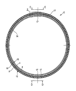
The stator ring 2 shown in Figure 1 is of a ring-shaped configuration
and forms a part of a ring generator with an internal rotor. The stator ring
2 has an inner carrier ring 4, a central carrier ring 6 and an outer carrier
ring 8. Provided between the inner and outer carrier rings 4, 6 is an active
cooling portion 10 while a passive cooling portion 12 is provided between
the central and outer carrier rings 6, 8. As illustrated the stator ring 2 is
cast in one piece including the inner, central and outer carrier rings 4, 6, 8
and active and passive cooling portions 10, 12, the material used being
aluminium.
The inner, central and outer carrier rings 4, 6, 8 provide for stability
and stiffness by virtue of their substantially solid nature. To guide a
magnetic field, a suitable magnetically well-conductive laminated core
CA 02739500 2011-04-01
14
carrying stator windings is to be arranged inwardly on the inner carrier ring
4. The laminated core can be fixedly carried by virtue of its fixing to the
inner carrier ring 4. Then, in the appropriate manner, an internal rotor is to
be arranged mounted rotatably relative to the stator within that laminated
core. Heat from the laminated core can be delivered directly to the ambient
air, but heat is primarily delivered by way of the carrier ring 4 to the
active
cooling portion 10 and the passive cooling portion 12. The active cooling
portion, for delivering heat, then has a plurality of active cooling passages
14 which are of a substantially triangular configuration in the active cooling
portion 10 between the inner and central carrier rings 4, 6. Further heat
can be discharged by way of the passive cooling passages 16 which are
approximately square or trapezoidal in cross-section.
The stator ring 2 is approximately of an outside diameter of 5 m. The
axial extent is about 90 cm.
The passive cooling passages 16 each have a radially outwardly
directed outlet flow opening so that only the active cooling passages 14 can
be seen in the rear view shown in Figure 2.
Radially outwardly directed outlet flow openings 18 are to be seen
from the side view in Figure 3 in accordance with the non-sectioned
illustrated portion which is shown at the bottom in Figure 3. Besides a
bevelled edge 20 of the inner carrier ring 4, the sectioned region shows a
view in axial section illustrating the shape of the active and passive cooling
passages 14, 16. In that case the active cooling passages extend
substantially axially from an inlet region 22 to an outlet region 24. The
passive cooling passage 14 extends from an intake flow opening 17 to the
outlet flow opening 18. The passive cooling passage 16 also extends
substantially in the axial direction, with the outlet flow opening being
directed radially outwardly. In addition the inlet region 22 of the active
cooling passage 14 is disposed on the side of the stator ring 2, that is
opposite to the intake flow opening 17 of the passive cooling passage 16.
Accordingly the stator ring 2 is also adapted to provide that an active air
flow through the active cooling passages 14 is directed in substantially
CA 02739500 2011-04-01
opposite relationship to a passive air flow through the passive cooling
passages 16.
Nonetheless those flow directions are not obligatory and an air flow
could also be guided by suitable devices in a direction other than the
5 above-described direction, at least through the active cooling passages.
In particular the cross-section of the active cooling passages 14 or
their respective inlet region 22 can be seen from the portion illustrated on
an enlarged scale in Figure 4. In that case the active cooling passages 14
are of a substantially triangular configuration in cross-section, being
10 arranged alternately with a differing orientation so that two adjacent
active
cooling passages 14 together in cross-section approximately assume the
shape of a parallelogram. In a corresponding fashion a respective boundary
wall is arranged between each two active cooling passages, wherein there
are always two boundary walls 26 of an active cooling passage 14 inclined
15 relative to each other.
The boundary walls 26 thus subdivide the active cooling passages 14
relative to each other and thus serve at the same time as cooling ribs. In
addition they afford a stable arrangement, in particular a stable connection
between the inner carrier ring 4 and the central carrier ring 6 by virtue of
the alternately inclined arrangement.
Furthermore additional cooling means of a limb-like configuration or
cooling ribs 28 are provided in the active cooling passages 14, being shown
on an enlarged scale in Figures 5 and 6 respectively.
The cooling ribs 28 thus increase the cooling area in the active
cooling passage 14 without noticeably impeding an air flow.
For fixing purposes inner carrier ring bores 34 are provided on the
inner carrier ring 4. In a corresponding fashion central carrier ring bores 36
are provided in the region of the central carrier ring 6 and in the region of
the passive cooling portion 12 adjacent to the outer carrier ring 8 the stator
ring 2 has outer carrier ring bores 38. At least some of the bores 34, 36
and 38 are provided with a screwthread and can be used for fixing
purposes. The outer carrier ring bores 38 serve for fixing the stator ring 2
to a stator bell.
CA 02739500 2011-04-01
16
The central carrier ring bores 36 are provided at some locations on
the carrier ring by auxiliary surfaces 35, more specifically three bores at
each of four locations. They serve for fixing cables.
Figure 7 is a cross-sectional view showing how a passive cooling
passage 16 is arranged between the outer carrier ring 8 and the central
carrier ring 6. In this case the passive cooling passage 16 extends from the
intake flow opening 17 to the outlet flow opening 18. An air flow can thus
flow substantially in the axial direction in through the inlet opening 17 and
flow out at the end through the radially outwardly directed outlet flow
opening 18. In this case a side of the outer carrier ring 8, that is remote
from the passive cooling passage 16, is an outside 30 of the stator ring 2.
In accordance with the appropriate requirements therefore air flows along
both sides of the outer carrier ring 8, namely on the inside through the
active cooling passage 16 and on the outside along the outside 30.
The active cooling passage 14 is provided between the central carrier
ring 6 and the inner carrier ring 4. It extends from the inlet region 22 to
the outlet region 24. The central carrier ring 6 also has blind holes 37
serving for fixing a rain gutter.
The perspective view in Figure 6 shows external fixing regions 31
and 33 at the leeward and windward sides respectively, which are only
partly shown and which are described in greater detail hereinafter with
reference to Figure 12.
Figure 8 also shows how the passive cooling passages 16 open
towards the outside 30 through their outlet flow openings 18. The fact that
the outlet flow openings 18 are directed radially outwardly means that an
end portion 40 in which the outer carrier ring bores 38 are arranged is
afforded downstream of the passive cooling passages 16, as viewed from
the appropriate wind direction in operation.
Figure 9 shows a view directly on to the intake flow openings 17 of
the passive cooling passages 16. As already shown in Figure 7 it can be
seen that the passive cooling passages 16 narrow slightly from the intake
flow opening 17. That can promote the flow of wind into the intake flow
openings 17. In the region of the outer fixing regions 31 and 32
CA 02739500 2011-04-01
17
respectively the passive cooling passages can be in the form of somewhat
smaller passive cooling passages 16' with correspondingly reduced intake
flow openings 17' in order to provide somewhat more massive intermediate
walls 19 for the provision of bores, in particular with a screwthread. The
intermediate walls 19 which do not have any bores can be somewhat
narrower in order thereby to provide more space for a larger passive
cooling passage 16.
The sectional view in Figure 10 provides a view on to cut-open
passive cooling passages 16. Once again the taper of the passive cooling
passages from the intake flow opening 17 to the outlet flow openings 18 is
shown here. The gauge of the intermediate walls 18 correspondingly
increases in the same direction.
The perspective view of the portion shown in Figure 11 illustrates in
the foreground the outlet region 24 of the active cooling passages 14 and
also the intake flow openings 17 and 17' of the passive cooling passages 16
and 16'. The leeward and windward external fixing region 31 and 32
respectively is arranged on the outer carrier ring 38 in the region of the
somewhat narrower passive cooling passages 16. Smaller outlet flow
openings 18' are correspondingly provided.
The external fixing regions 31 and 32 respectively are each provided
at locations on the stator ring 2, that are arranged in mutually opposite
relationship, that is to say arranged displaced through 180 , as can be seen
in Figure 1 at the two by three somewhat reduced intake flow openings 17'
at the 12 o'clock and 6 o'clock positions. A plan view of the one location is
shown in Figure 12, accordingly the leeward external fixing region 31 has
eight leeward bores 41 whereas the windward external fixing region 32 has
eight windward bores 42.
The stator bell 100 in Figures 13 to 15 includes a machine carrier
fixing 102, a stator ring fixing 104 and a trunnion fixing 106. The machine
carrier fixing 102, the stator ring fixing 104 and the trunnion fixing 102 are
each in the form of a circular fixing flange each having one or two
peripherally extending rings of holes.
CA 02739500 2011-04-01
18
Six carrier portions 108 extend from the machine carrier fixing 102
approximately in a star-shaped configuration to the stator ring fixing 104.
The carrier portions 108 are in the form of carrier arms 108 to be able to
carry the force due to the weight of a stator fixed to the stator ring fixing
104 and to be able to transmit it to a machine carrier by way of the
machine carrier fixing 102.
The regions between the carrier portions 108 are respectively
spanned over by plate-like portions, with respective fan openings 110 being
provided therein. In addition auxiliary openings 112 are provided in some
carrier portions 108.
In addition provided in the region of the trunnion fixing 106 is an
opening which however is closed by fixing of a trunnion in the appropriate
fashion.
Thus the entire stator bell 100 is closed by closing the fan openings
110, in particular by means of fans, and the auxiliary openings 112. By
virtue of fixing a stator to the stator ring fixing 104 and the provision of a
corresponding rotor, a pressure chamber can be formed between that
stator and the rotor on the one hand and the stator bell 100 on the other
hand, and can be subjected to pressure. The air can escape through
openings in the rotor-stator arrangement, such as for example the air gap,
and in that case leads to an air flow in the opened regions in question.
Figure 16 shows the stator bell 100 together with a stator ring 2*
which is fixed to the stator ring fixing 104 on. the stator bell 100. In
addition arranged in each fan opening 110 is a fan 114 which together with
a fan cover 116 closes and covers the fan opening 110.
By bringing one or more of the fans 114 into operation air is blown
into the space covered or enclosed by the stator bell 100. The air can
escape through openings in the generator of which the stator ring 2* forms
a part, and provide for cooling. For that purpose the auxiliary openings 112
are also closed with a cover, although this is not shown in detail in Figure
16. It will be appreciated that the fans 114 can also operate in such a way
that they suck air out of the space covered by the stator bell 100, as shown
in Figure 16 therefore substantially towards the right and out of the plane
CA 02739500 2011-04-01
19
of the drawing. Nonetheless the preferred case involves blowing into the
covered space air which, with the appropriate arrangement of the stator
bell 100, comes from a corresponding pod and leads to the expectation of
better purity and dryness in comparison with external air from outside the
pod.
Figure 17 now shows how, in accordance with the invention, the fan
openings 110 can be used for maintenance or other purposes. For example
in the case of a fan opening 110 the fan 114 is folded away by means of a
hinge and the fan opening 110 is correspondingly opened. Now a person
can pass through that opened fan opening 110, through the stator bell 100,
more specifically through the fan opening 110 to the ring generator
arranged therebehind. Equally, instead of a hinge for folding the fan 114
away, it is also possible to provide another motion mechanism. A quick-
action clamping fastening can also easily be used for opening the fan
opening 110. For that purpose, such a quick-action clamping fastening can
be released with a few manual operations and the corresponding fan 114
can thus be removed. If a fan opening is only partially opened or if the
opening is still blocked by other devices, as is shown for example at an
opening 110*, so that a person cannot climb therethrough, partial
maintenance can still be considered in respect of the devices arranged
immediately behind the opening. The same applies to the smaller auxiliary
openings 112.
Figure 18 diagrammatically shows the overall concept according to
the invention by means of an embodiment by way of example. Figure 18
shows a lateral view in section of a portion of a pod 250 having a rotor
assembly 252 with rotor blades 254, a ring generator 200 having a rotor
201 and a stator 203 with a stator ring 202 and a laminated core 205 with
stator windings 27 which are only diagrammatically indicated. An air gap
209 is arranged between the stator 203 and the rotor 201. The stator ring
202 has an inner carrier ring 204, a central carrier ring 206 and an outer
carrier ring 205. Provided between the inner and outer carrier rings 206,
208 are passive cooling passages 216 forming a passive cooling portion
212. Active cooling passages 214 are arranged between the inner carrier
CA 02739500 2011-04-01
ring 204 and the central carrier ring 206 and form an active cooling portion
210.
A stator bell 260 is fixed in the region of the central carrier ring 206
and a separating portion 262 is provided adjoining the magnetically
5 operative part of the rotor 201. Arranged in the stator bell 260 are fans
264
which lead to an increased pressure in the pressure chamber 266 arranged
substantially between the stator bell 260 and the separating portion 262.
By virtue of the pressure built up in that way in the pressure chamber 266
air flows through the air gap 209 and the active cooling passages 214. The
10 generator and in particular the stator is thus cooled by the air flow 270
through the air gap 209 and the active cooling passages 214.
Portions of the pod casing 251 including portions of the hub casing
251* extend at the level of the central carrier ring 206. Thus in relation to
the pod 250 the ring generator 200 including the active cooling portion 210
15 is arranged within the pod 250. Only the passive cooling portion 212 and
thus the passive cooling passage 216 are arranged outside the pod 250.
The rotor 252 and the rotor blade 254, that is to say as shown in Figure 18
the part at the left of the pod 250, namely the hub with the hub casing
251* or spinner is facing into the wind in operation of the arrangement.
20 Wind which flows to the pod 250 thus firstly flows along the hub casing
251* in the region of the rotor 252.
The pod casing 251* is lowered in a region and, is thus at the same
level as the central carrier ring 206. The hub casing can be at the level of
the outer carrier ring 208 in the region of the rotor blade attachment, as is
shown in Figure 18 by reference 251**. Figure 18 shows a snapshot in that
respect. It should be mentioned that a rain gutter can be mounted to the
stator ring 202 in the region of the central carrier ring 206 on the side
towards the hub casing 251* in order to prevent the ingress of rainwater in
that region and thus to protect the elements of the ring generator 200, that
are arranged within the pod, from rainwater.
Then the wind passes from the region of the depressed hub casing
251* into the region of the intake flow openings 217 and to the passive and
thus outer cooling portion 212 and can there flow into the passive cooling
CA 02739500 2011-04-01
21
passages 216 through the intake flow openings 217 and cool the stator ring
202 in that region.
It is to be noted that the fan 264 leads to an active cooling flow 270
flowing through the air gap 209 and the active cooling passages 214. The
wind results in a passive cooling flow 272 flowing through the passive
cooling passages 216. It is to be noted that the active cooling flow 270 is in
opposite relationship to the direction of the passive cooling flow 272. More
specifically, basically the fan or fans 264 urge air out of the pod interior
253 through the stator bell 260 into the pressure chamber 266 and from
there through the air gap 209 and the active cooling passages 214
outwardly in the direction of the rotor assembly hub 256 and thus in
opposite relationship to the wind.
The views in Figures 19 to 22 diagrammatically show a pod 250. In
particular a pylon, rotor assembly blades and any pod structures such as an
anemometer or the like are not shown or are only basically shown. The
perspective view in Figure 19 inclinedly from the front on to the pod 250
substantially shows the pod casing 251 and the hub casing 251* and 251**
respectively. In particular it is possible to see a part of the ring of outlet
openings 218 and inlet openings 217 of the passive cooling portion 212. As
shown in Figure 19 therefore in regular operation the wind comes
approximately from the right into the plane of the drawing, flows along the
hub casing 251 into the intake flow openings 217 through passive cooling
passages in the passive cooling portion 212 and leaves the passive cooling
portion 212 again in the region of the outlet flow openings 218. In that
case in regular operation the wind flows approximately in the axial direction
into the intake flow openings 217 while it at least partially leaves the
outlet
flow opening 218 directed outwardly in the radial direction.
Figure 19 shows three rotor blade attachments 274 on the hub
casing 251* and 251** respectively. Shown in the proximity thereof - in
Figure 19, in particular in regard to the rotor blade attachment 274 shown
at the left - is a transitional edge 276 between the higher region of the hub
casing 251** and the lower region of the hub casing 251*. The higher hub
casing region 251** is approximately aligned with the outer carrier ring
CA 02739500 2011-04-01
22
208 and thus covers the intake flow openings 217. The lower region of the
hub casing 251* is approximately aligned with the central carrier ring 206
so that the intake flow openings 217 can be seen in the region in question
and can also be reached by the wind.
The front view on to the pod 250 in Figure 20 substantially shows the
hub casing 251* and 251** respectively and the intake flow openings 217.
The perspective in Figure 20 corresponds to the regular wind intake flow
direction. In addition the windward-side external fixing region 232 is
arranged at the 12 o'clock position. It will be clear from the further
perspective view in Figure 21 and the perspective side view in Figure 22
that rotor blade portions 278 at the pod side can pass over the region of
the passive cooling portion 212 and in so doing the intake flow openings
217 and the outlet flow openings 218.